Advertisement
Table of Contents
- 1 Wall Mount Dimensions
- 2 Environmental Requirements
- 3 Wall Mount Installation
- 4 Rack Mount Considerations
- 5 Wiring Requirements
- 6 Part Numbers
- 7 Visual Indicators
- 8 Access Control Module
- 9 Switches and Jumpers
- 10 Ports and Connectors
- 11 Wiegand Connections
- 12 Address Configuration
- 13 Compliance Information
- 14 Important Safety Information
- Download this manual
OVERVIEW
NOTE
General Control
Module
The iSTAR Ultra SE can be configured as an iSTAR Pro (in Pro Mode) or as an
iSTAR Ultra (in Ultra Mode for use with C•CURE 9000). The configuration is
based upon the GCM S1-4 switch setting.
The iSTAR Ultra SE in Pro Mode is supported by C•CURE 9000 and C•CURE 800/8000. Refer to
the iSTAR Pro Controller software configuration information when using the C•CURE 9000 or the
C•CURE 800/8000.
Pro Mode does not support the optional RC4 network encryption setting in either C•CURE 800 or
C•CURE 9000 systems. Check the Message Encryption system variable to ensure RC4 is not being
used.
The iSTAR Ultra SE in Ultra Mode is only supported on C•CURE 9000 v2.50 and higher. Refer
to the iSTAR Ultra Controller software configuration information when using the C•CURE 9000.
The iSTAR Ultra SE in Ultra Mode has a reduced feature set when compared to the iSTAR Ultra.
There are 16 Inputs instead of 24 and 8 Relays instead of 16, per ACM and no embedded lock
power management.
The iSTAR Ultra consists of the following hardware components:
General Controller Module (GCM)
Access Control Module (ACM) - 2 maximum
or IP-ACM Ethernet Door Modules (supported in Ultra Mode only) - 32
maximum (IP-ACM installation and configuration is not included in this
document, see the IP-ACM Ethernet Door Module Quick Start Guide)
The GCM is a General Purpose Module running the Linux
The GCM provides the following features:
Two network Gigabit Ethernet ports.
An LCD panel that displays the current status, and provides built-in
diagnostics.
iSTAR Ultra SE Controller
Hardware Installation
Version D0
Part Number UM-311
October 2017
®
operating system.
1
Advertisement
Table of Contents

Related Manuals for Software House iSTAR Ultra SE


Summary of Contents for Software House iSTAR Ultra SE
- Page 1 to the iSTAR Ultra Controller software configuration information when using the C•CURE 9000. The iSTAR Ultra SE in Ultra Mode has a reduced feature set when compared to the iSTAR Ultra. There are 16 Inputs instead of 24 and 8 Relays instead of 16, per ACM and no embedded lock power management.
- Page 2 1 reader per IP-ACM or a maximum 16 IP-ACMs with 2 readers per IP- ACM. The limiting factor is a maximum of 32 readers. For the iSTAR Ultra SE to operate with the IP-ACM v1 modules, the GCM ...
-
Page 3: Wall Mount Dimensions
Requirements Types of Mounting The iSTAR Ultra SE, and its components, can be installed in a wall mount enclosure or in a separate rack mount enclosure. REQUIREMENTS Site Requirements Ensure that the site is ready: The iSTAR Ultra SE installation must be performed by a certified installer. -
Page 4: Wall Mount Installation
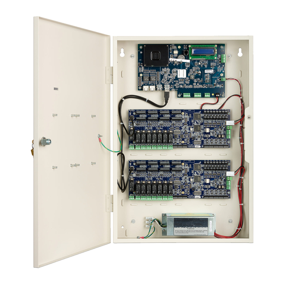
The cables are protected by use of conduit, which is metal, plastic, or flexible cable grip strain relief. An external power supply provides 12 Vdc to power the iSTAR Ultra SE. If an ACM is powered by a different Power Supply Unit (PSU), the ACM Fail trigger must be configured to alarm on failure. - Page 5 Installation Figure 1. iSTAR Ultra SE Controller with Door Removed (Two ACMs Mounted) General Controller Keyhole Module (GCM) Mounting Assorted Knockouts Cabinet/Enclosure Slot (2) Tamper Switch Tamper Ground Stud E-Net (6-32) For Shield Wire, 1 By Each Knockout Reader & Logic Power...
- Page 6 Wall Mount Door Components The wall mounted iSTAR Ultra SE has stand-off’s on the enclosure door that can support up to two RM Bus components. The I/8, I/8-CSI, R/8, and RM-4E boards are supported. There can be any combination of these boards.
-
Page 7: Rack Mount Considerations
Use a service loop when connecting the cables. NOTE Rack Mount Considerations If you are mounting the iSTAR Ultra SE in Pro Mode as a rack mount, the ACM must be NOTE tampered with a supervised input dedicated as a tamper. - Page 8 Disconnect all sourced power before modifying the wiring. POWER This section provides the power requirements for the iSTAR Ultra SE and its components. A limited power supply (LPS class 2) is required. Electrical Electrical ratings are dependent upon the configuration.
- Page 9 AC Power 100-240 VAC~1.7A, 50-60Hz The iSTAR Ultra SE comes with the power supply installed. There is an optional powers supply that can be purchased (STAR-PS or USTAR-PS) for Access Control only, not standby-power. USTAR-PS has not been evaluated by UL.
- Page 10 Power The iSTAR Ultra SE must be supplied by a 15A circuit breaker protected branch-circuit. FOR BURGLAR ALARM INSTALLATIONS: The iSTAR Ultra SE is not provided with backup power. An external power supply must be provided with the following characteristics: UL 603 and/or UL 294 Listed ...
-
Page 11: Wiring Requirements
configured in C•CURE 9000 or C• 800. Ethernet cabling must be CAT-5E or better. The Power Input terminals on the iSTAR Ultra SE accept conductor size up to 2mm AWG). Table 3 on page 11 lists the general wiring requirements for an iSTAR Ultra SE and its components. - Page 12 RM-4, RM-4E, RM-DCM-2 iSTAR Ultra SE also supports the following wireless reader combinations: 16 Schlage PIMs and 16 Readers - only one GCM RS-485 Port (Pro Mode) 32 Schlage PIMs and 32 Readers (Ultra Mode) ...
-
Page 13: Part Numbers
Table 4. Part Numbers Part Number Description USTAR008-SE iSTAR Ultra SE with one GCM, one ACM, one wall mount enclosure, and a power supply. Supports up to eight readers. USTAR016-SE iSTAR Ultra SE with one GCM, two ACM’s, one wall mount enclosure, and a power supply. - Page 14 General Control Module GENERAL CONTROL MODULE...
- Page 15 The SW7 push button saves all data in non-volatile memory and then reboots the unit. It may take several minutes for the formatting and saving of the data. The iSTAR Ultra SE is fully capable of operating without contact with the Host after the reboot.
- Page 16 The Encryption switch enables FIPS 197 AES 256-bit encryption. The switch setting must match the software configuration of the cluster and the controller. When S1-1 is turned ON, followed by a factory reset, the iSTAR Ultra SE controller in Ultra Mode becomes encrypted and can cluster with the following...
- Page 17 CPNI - S1-2 When this switch is set to ON, the iSTAR Ultra SE runs in CPNI (Centre for the Protection of National Infrastructure) mode and all database and transactions are stored in RAM. The database and transactions are not backed up on the SD.
- Page 18 General Control Module Figure 3. AC Fail - Low Battery J2 AC Fail Input Indicates whether the external power source has reported loss of its main power. Shares the connector and Ground pin with Low Battery. Normally closed dry relay contacts are required. This signal is usually wired ...
-
Page 19: Visual Indicators
USB Micro Type AB - J7 Not supported. Possible future option. RS-232 Diagnostic Port (P4) Software House Tech Support and Engineering use for troubleshooting. COMM Board Connector - J15 Not supported. VISUAL INDICATORS Power - DS1 and DS2 Indicates that power is supplied to the unit. -
Page 20: Access Control Module
Port 2 Receive Data ACCESS CONTROL MODULE The ACM provides Readers, Inputs, and Outputs used in access control. An iSTAR Ultra SE contains one or two ACMs. 8 RS-485 Reader Ports for RM Bus Devices. • Terminator switch for the RS-485 Port 8 Direct Connect Wiegand Port with LED drives. - Page 21 Access Control Module Inputs • Supervised Inputs (16 ports) SE Pro Mode - use standard Software House 1K dual EOL configuration. • Supervised Inputs (16 ports) SE Ultra Mode - supervision type is individually selected on each input. Pin 2 of each Input is grounded. All door components must come from the same controller.
-
Page 22: Switches And Jumpers
Access Control Module Figure 6 on page 22 shows the left side of the ACM and locates the USB client connector, ACM Reset, and some of the LED locations. Figure 6. Access Control Module - Left Side Switches and Jumpers S5 - ACM MCU Reset S5 reboots both MCUs. -
Page 23: Ports And Connectors
Access Control Module • S1-1 = ON ACM is unit 1 S1-2, S1-3, and S1-4 are not used and must be in the OFF position. NOTE Energize on FAI (SE Ultra Mode only) SW3, SW4, SW7, SW8, SW9, SW10, SW11, SW12 The relays can be configured to activate when the FAI signal goes true. -
Page 24: Wiegand Connections
Access Control Module Use only one of the connectors. Observe polarity when connecting power to P37 and P37-2. Failure to observe proper connection will damage the board. FAI F and Key - P45 (SE Ultra Mode only) The FAI signal is NC and the Key signal is NO. Wire the supervising resistors as shown in Figure 7 on page 24. - Page 25 Access Control Module 20 AWG - 300 feet 22 AWG - 200 feet Table 7 on page 25 describes the pinouts. Table 7. Wiegand Port Pinouts Wiegand Port Signal/Function Pin Number Power: +12 Vdc or +5 Vdc (set by P34 Jumper) GND - PWR Return Data 0 - Wiegand Input Data 1 - Wiegand Input...
- Page 26 Access Control Module S3 - LED - Beep Control for Wiegand Ports The C•CURE 9000 iSTAR Driver System Variables (or C•CURE 800/8000 Reader System Variables) and the reader must be configured for the desired pattern. Refer to the appropriate C•CURE and Reader guides. Table 9.
- Page 27 Access Control Module INPUTS P1, P2, P3, P4, P5, P6, P7, P8, P9, P10, P11, P12, P13, P14, P15, P16 There are 16 onboard inputs available on the ACM. When in Ultra Mode, the Input supervision method is individually selected in the host. However, when in Pro Mode, the input supervision method that is used is dual 1K ohm supervision, as shown below.
- Page 28 Access Control Module ACM LED Functions Table 11. ACM LED Functions Function Comment Main Power - Reader Power - J4 12 Vdc Relays DS27 Relay 1 Activated Dry Relay DS28 Relay 2 Activated Dry Relay DS29 Relay 3 Activated Dry Relay DS30 Relay 4 Activated Dry Relay...
- Page 29 Use the following sections to make an initial connection to the controller and facilitate any desired changes. Software House recommends that you use a Static IP address when configuring iSTAR controllers with member connected controllers and iSTAR controllers with connected IP-ACMs.
-
Page 30: Address Configuration
To configure the controller to use a DHCP IP address: Address Configuration 1. Connect to the network using the Ethernet port 1 of the iSTAR Ultra SE. 2. You can now use the iSTAR Configuration Utility (ICU), or the iSTAR Ultra Web Utility. -
Page 31: Compliance Information
Compliance Information COMPLIANCE INFORMATION Table 13. Standards Standard Description Notes Access Control System UL294 6 Edition Proprietary Alarm Units UL1076 5 Edition Proprietary Alarm Units Canada cUL1076 5 Edition CSA C22.2 No. 205 Signaling equipment Canada IEC60950-1 ITE – Safety International EN60950 ITE –... -
Page 32: Important Safety Information
IMPORTANT SAFETY INFORMATION CAUTION: Changes to the iSTAR Ultra SE not expressly approved by the party responsible for compliance could void your authority to operate the equipment. LIFE SAFETY REQUIREMENT: A fail-safe mechanism override must be installed at each card reader exit to allow people to leave the secure area in case of electromechanical device failure.
Need help?
Do you have a question about the iSTAR Ultra SE and is the answer not in the manual?
Questions and answers
I need to connect a push button on the ACM or the inputs module
To connect a push button to the ACM or inputs module of the Software House iSTAR Ultra SE, follow these steps:
1. Identify the Input Terminals: Locate the input terminals on the Access Control Module (ACM). The ACM provides multiple inputs for access control devices.
2. Determine the Wiring Type: Push buttons are typically wired as Normally Open (NO) or Normally Closed (NC) contacts. Verify the wiring configuration required for your system.
3. Connect the Wires:
- Connect one terminal of the push button to the designated input terminal on the ACM.
- Connect the other terminal of the push button to the common ground (GND) of the ACM.
4. Configure the Input in Software: In the system software, configure the assigned input to recognize the push button action (e.g., door release or alarm reset).
5. Test the Connection: Press the push button and verify that the ACM registers the input correctly.
Ensure proper wiring and configuration for the desired functionality.
This answer is automatically generated