Table of Contents
Advertisement
Quick Links
Advertisement
Chapters
Table of Contents

Related Manuals for HART HART475


Summary of Contents for HART HART475
- Page 1 现场通讯器用户手册 COMMUNICATOR User’s Manual...
-
Page 2: Table Of Contents
目录 第一章 简介…………………………………………………… 2 第二章 基本使用……………………………………………… 3 2.1 现场通讯器的基本性能和功能…………………………………… 3 2.2 开机注意事项……………………………………………………… 4 2.3 键区的使用和说明………………………………………………… 5 第三章 在线操作菜单………………………………………… 7 3.1 检测菜单…………………………………………………………… 7 3.1.1 轮询检测……………………………………………………… 7 3.1.2 按轮询号检测………………………………………………… 8 3.1.3 选择设备类型………………………………………………… 8 3.2 压力变送器主菜单………………………………………………… 9 3.2.1 过程变量……………………………………………………… 9 3.2.2 组态与测试 ………………………………………………… 10 3.2.3 特征化…………………………………………………………13 3.2.4 校准……………………………………………………………19 3.2.5 显示模式………………………………………………………21... -
Page 3: 第一章 简介
第一章 简介 感谢您使用 HART475D 现场通讯器, 本通讯器适合 HART 协议智能变送器的通讯操作,与 HART275、HART375、兼容, 具有极好的兼容性,可通讯 1151,3051,EJA,ABB,科式及流 量等方面的 HART 协议的进口仪表。 完全兼容国产的各种智能 变送器。 该手册介绍了现场通讯器基本的使用、连接和操作方面 的内容以及故障的排除和在使用过程中应该注意的事项。 在使用 HART 现场通讯器之前,请阅读该该操作手册, 为了更好发挥该产品的最佳性能,在使用或维修本产品之 前,请深入掌握相应的内容。 如若设备需要维修,请联系我们公司。我们将竭尽所能 为您服务。 该设备配备: 手操器 一台 电池(手操器内) 一块 包 一个 充电器 一部 通讯线缆 一条 操作手册 一本... -
Page 4: 第二章 基本使用
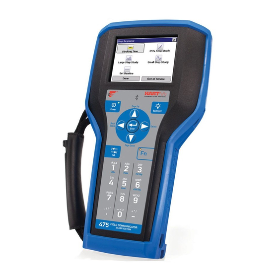
第二章 基本使用 2.1 现场通讯器的基本性能和功能 24V 开关 通讯电缆 DC24V 电池显示 显示区 四个导航键 确认键 开/关键 PV 键 数字字母按键区 4.2V 充电器接口 左中右选择键 现场通讯器示图... -
Page 5: 开机注意事项
2.2 开机注意事项 在开机前,请确保以下几点: ·该现场通讯器没有物理机械损坏 ·电池已充满电。 ·将现场通讯器连接到仪表(如图 2-2) 连接图: 通讯接线图。 启动现场通讯器 在启动前请保证该设备已充好电。启动时按住电源开关键,直 到液晶屏亮,开机成功。 关闭 如若要关闭现场通讯器,可按住开关键直至其显示关闭,关闭输出电源 开关,关机完成。 充电 充电时使用通讯器配备的专用充电器,将充电插头插入通讯器充电口, 充电器指示灯由绿色变为红色,开始充电,电池从没电到充满大约需要八 小时,当电充满后,指示灯会变为绿色。... -
Page 6: 键区的使用和说明
2.3 键区的使用和说明 开关键 该键用于启动或关闭现场通讯器。 箭头导航键 四个导航箭头键提供菜单的选择功能。 按 右箭头的导航键,可以进入某一菜单的具体选项。按 左导航键返回上级菜单, 上下导航键可以在菜单中上下切 换。在字符数字输入模式, 下导航键可以作为退格键使用。 回车键 在进入菜单后,对于可以修改的内容,液晶的最下面一 行会自动显示“修改”字样若需修改则按下回车键,即修改成功。 字符数字键盘 字符数字键盘可以输入字符、数字以及其他符号,他有数字和 字符两种输入模式,现场通讯器可根据需要选择相应的输入模式。 若要输入数字,直接按下数字所在的键,若要输入字符,可根据字 符在键盘上的位置,先按下... - Page 7 中的一个键,再按下字符所在的键。例如要输入字符〝A〞,先 左选择键,再按下字符数字 1 键盘。 按下 PV 键 监测实时变量的快捷键,观察实时压力、电流、百分比、 温度、频率等实时变量。在字符数字输入模式下,该键无效。...
-
Page 8: 第三章 在线操作菜单
第三章 在线操作菜单 检测菜单 选择检测方式: 1.轮询检测 2.按轮询号检测 图 3-1 3.1.1 轮询检测 选择该菜单,现场通讯器将从轮询号 0 到轮询号 15 依次检测 设备,若检测到设备,将自动显示检测到变送器及工位号(如图 3-1-1) ,按 右导航键进入设备类型选择菜单(图 3-1-2) ;若没 有检测到设备,将出现没有检测到变送器的警告。... -
Page 9: 按轮询号检测
3.1.2 按轮询号检测 对指定轮询号的设备进行检测,按 上下导航键可以 在 0~15 之间选择轮询号,然后按 右导航键开始检测(检测结 果同于 3-1-1) 。 检测到变送器: 工位号[DS8001] 图 3-1-1 3.1.3 选择设备类型 选择设备类型: 1.压力变送器 1.压力变送器 2.电磁流量计 电磁流量计 3.涡街流量计 4.靶式流量计 3.涡街流量计 5.金转流量计 4.靶式流量计/浮筒液位计 6. 科式质量流量计 5.金转流量计 3-1-2 图 6. 科式质量流量计 7. 通用菜单 8. 语言设置 对设备类型进行选择时,必须根据现场设备类型进行选择 进入具体的菜单,如果选择类型与实际类型不符,会造成错误。... -
Page 10: 压力变送器主菜单
如果现场设备非压变、电磁、涡街、靶式、金转、科式设备则 进入通用菜单进行连接。按 上下导航键选择好设备类 型,再按 右导航键进入所选设备类型检测,并进入相应的菜 单,如果选择类型与检测不符会进行提示。 压力变送器主菜单 子菜单 1. 过程变量 主菜单: 1.过程变量 2. 组态与测试 2.组态与测试 3.特征化 3. 特征化 4. 校准 图 3-2-1 5. 显示模式选择 6. 通用格式化 3.2.1 过程变量 实时显示变送器的压力, 百分比, 电流, 温度等参数。 按 左导航键 3 秒后弹起方可退出实时变量监测模式。 压 强 –0.258 电 流 4.820 百分比... -
Page 11: 组态与测试
3.2.2 组态与测试 子菜单: 组态与测试 1.设备测试 1.设备测试 2.回路测试 2.回路测试 3.用户量程 3.用户量程 图 3-2-3 4.基本设置 3.2.2.1 设备测试 检测设备状态,若一切正常,液晶显示“设备正常” ,若有错 误,将出现警告提示。 3.2.2.2 回路测试 检测 D/A 的电流输出。先在回路里串连一个电流表,再键入 一个 4-20mA 之间的电流值,送入变送器,变送器会自动输出键 入的电流值,若键入的值与电流表的显示值不相等,需做电流微 调。... - Page 12 3.2.2.3 基本设置 子菜单: 1. 单位 基本设置 2. 写保护 1.单位 3. 阻尼 2.写保护 3.阻尼 4. 输出方式 5. 设备信息 图 3-2-4 6. 材料信息 单位 修改主变量的单位,以及显示的单位。提供 MPa,Kpa, Pa,InH2O,InHg,psi,g/cm²,kg/cm²,FtH2O,torr,ATM, O,mmHg,Bar,mBar 这 15 种单位。当测量单位代 号无法识别时会自动显示“No”即表示单位“unknow” 。修 改方法见菜单树。 写保护 读写设备的保护状态,当为写保护时,变送器内部数据不 可改。 阻尼 读写设备的阻尼系数(保留三位小数点) 。单位为秒。...
- Page 13 输出方式 读写设备的输出方式。分为线性、开方以及未知。默认为 线性。 设备信息 读写工位号,日期,描述符,信息,最终装配号。 轮询号 3.2.2.4 用户量程 用户量程 1.键盘输入 2.提供压强值 图 3-2-5 键盘输入 选择此菜单后,首先提示传感器的量程范围,然后进入 量程设定菜单, 按 上下导航键选择零点或量程, 然后 输入用户需要设定的数值 (保留三位小数) , 再按 右导航键 送入变送器。 传感器量程 用户量程 L –180.000KPa L –180.000KPa H 180.000KPa H 180.000KPa 图 3-2-6 图 3-2-7...
-
Page 14: 特征化
提供压力值 用变送器当前所受压力值设定零点和量程,按 上下 导航键选择,按 右导航键确定。 提供压力值 1.零点 2.量程 图 3-2-8 3.2.3 特征化 子菜单: 1. 传感器微调 2. 传感器量程 3. 用户量程 特征化 4. K 系数 1.传感器微调 2.传感器量程 5. 温度补偿 3.用户量程 6. 小信号切除 7. 设备地址 图 3-2-9 8. 数据备份 9. 数据恢复... - Page 15 该菜单下的操作会严重影响变送器的正常工作和精 度,因此在进入此菜单时,需要输入验证密码(如图 3-2-10)。 请输入密码: ****** 图 3-2-10 默认密码为:666666 3.2.3.1 传感器微调 传感器微调 1.零点微调 2.低端微调 3.高端微调 零点微调 图 3-2-11 给变送器加0压力后选择此操作,变送器自动调节零点。 低端微调 给变送器加低端压力(单位 KPa) ,键入所加的压力值(保留 三位小数) ,变送器自动校正,使输出为所加的压力值。 高端微调...
- Page 16 给变送器加高端压力(单位 KPa) ,键入所加的压力值(保留 三位小数) ,变送器自动校正,使输出为所加的压力值。 3.2.3.2 传感器量程 传感器量程 1.选择传感器量程 2.修改传感器量程 图 3-2-12 选择量程 先选择传感器的类型,然后选择传感器的量程代码,再按下回 车键送入变送器。 (如图 3-2-13、3-2-14) 量程代码 传感器类型 [5] [差压 ] 推出 推出 图 3-2-14 图 3-2-13 修改量程 先选择传感器的量程代码,然后输入该量程代码的量程范围。 注意:输入的压力单位为 Pa,只能输入正整数。改后再选择传 感器量程。...
- Page 17 3.2.3.3 用户量程 键盘输入 选择此菜单后,首先提示传感器的量程范围,然后进入量程 设定菜单,按 上下导航键选择零点或量程,然后输入用户 需要设定的数值 (保留三位小数) , 输入好后 按右导航键送入变 送器。 传感器量程 用户量程 L –180.000KPa L –180.000KPa H 180.000KPa H 180.000KPa 图 3-2-16 图 3-2-15 提供压力值 用变送器当前所受压力值设定零点和量程,按 上下导航 键选择,按 右导航键确定。 提供压力值 1.零点 2.量程 图 3-2-17...
- Page 18 3.2.3.4 K 系数 必须先做低端,再做高端。 K系数 1.低端 2.高端 图 3-2-18 低端 给变送器加 0 压力,键入所加的压力值 0,按 右导航键 送入变送器,变送器自动调节 k 系数低端。 高端 给变送器正端加一个压力(接近或等于物理量程),所加压力必 须大于 0 压力,键入所加的压力值(保留三位小数,单位 KPa) ,按 右导航键送入变送器,变送器自动调节 k 系数高端。 K 系数必须在正压力情况下操作,且输入的单位为 KPa。 注意: 3.2.3.5 格式化 全量程格式化 注意:该操作会严重影响变送器的精度,建议用户最好不要 自己做格式化。 操作方法:先给变送器加压力 (各点压力必须从负压力最大 到正压力最大),然后输入所加的压力值(图 3-2-16,注意:在负 压力端做格式化时,输入的压力值前面要加负号。...
- Page 19 航键执行格式化,成功后返回到下一个点的格式化,不成功返回 警告提示。 全量程:第 01 点 压强:[ 图 3-2-19 插补 校正格式化后超差的点。 注意:该操作会严重影响变送器的精度,建议用户最好不 要自己做格式化。 操作方法:先给变送器加压力,然后输入所加的压力值。 (注意:在负压力端做格式化时,输入的压力值前面要加负号) 。 按 右导键后,插补完成,此时该点测得的压力应基本等于 所加压力。 插补 压强:[ 图 3-2-20...
- Page 20 3.2.3.6 小信号切除 该功能是为了消除零点漂移。输入的数为用户量程的 万分比。 3.2.3.7 设备地址 查看设备的地址。设备地址是该智能板的唯一识别号。 3.2.3.8 数据备份 数据备份:将当前用户量程值和格式化的数据全部备 份到 FLASH 数据库中,此功能是以便于误操作后数据恢复。 单击菜单中“数据备份”即可 3.2.3.9 数据恢复 数据恢复:在仪表出厂前,厂商已经对仪表进行了格式 化操作,并将格式化后的正确数据做了备份,当用户误操作 使仪表不能工作时,可以使用“数据恢复”功能将其误操作 内容清除,并且重新将厂商初始化的备份数据重新写入仪表, 便于仪表恢复原数据。单击菜单中“数据恢复”即可。 3.2.4 校准 子菜单 校准 1.传感器微调 1.传感器微调 2.输出微调 2.输出微调 图 3-2-21...
- Page 21 3.2.4.1 传感器微调 传感器微调 1.零点微调 2.低端微调 3.高端微调 图 3-2-22 零点微调 给变送器加0压力后选择此操作,变送器自动调节零点。 低端微调 给变送器加低端压力(单位 KPa) ,键入所加的压力值(保 留三位小数) ,变送器自动校正,使输出为所加的压力值。 高端微调 给变送器加高端压力(单位 KPa) ,键入所加的压力值(保 留三位小数) ,变送器自动校正,使输出为所加的压力值。 3.2.4.2 输出微调 输出微调需要将一个高精度电流表串联到回路,在进入微 调时,液晶会提示接入电流表,在退出电流微调时,液晶会提 示恢复回路。 警告: 请将电流表接入 回路! 图 3-2-23...
-
Page 22: 显示模式
4mA 电流微调 选择 4mA 电流微调,此时输出应该为 4.000mA,若电流表 显示的数值不等于 4.000mA,选择“否” ,出现输入框,在输入 框里键入电流表显示的数值 (保留三位小数) , 然后按 右导航 键把输入的电流值送入变送器,变送器会自动校正电流输出, 使输出为 4.000mA,若一次达不到理想效果,可重复此操作。 (注意:电流表精度应该高于表的输出精度) 输出微调 1.4mA 微调 2. 20mA 微调 图 3-2-4 20mA 电流微调 操作方法与 4mA 电流微调相同。 3.2.5 显示模式 选择此模式,变送器显示百分比。 2.USER SET 选择此模式,变送器显示用户设置。 3.USER SET&% 选择此模式,变送器显示用户设置和百分比每隔 4S 交替 显示。... -
Page 23: 通用格式化
4.INPUT PRESS 选择此模式,变送器只显示输入压力。 5.INPUT PRESS&% 选择此模式,变送器显示输入压力和百分比每隔 4S 交替 显示。 显示模式 1.% 2.USER SET 3. USER SET&% 图 3-2-25 3.2.6 通用格式化 通用格式化: (即通常所说的三点,五点格式化) (1)选择仪表类型和量程代码,确定仪表的物理量程。 (2) 在通用格式化里进入格式化,原装板 1151 电流会为 22mA,次序为物理量程的 0%,60%,100%三点格式化,或 0%,60%,100%,-60%,-100%五点格式化。根据通讯器 第一行显示的物理量程的百分数计算压力,输入其压力并 填写压力值(单位为 Pa) ,待压力稳定后按右键头发送。 (3) 操作成功后,显示下一点的百分数,继续操作或退出。 操作失败(如加的压力与显示百分比对应的压力相差 太大会返回此点重做。三点格式化在做完 100%点后按退出 完成,五点格式化在做完-100%自动退出。退出后电流由 22mA 变为测量值的电流。... -
Page 24: 电磁流量计主菜单
3.3 电磁流量计主菜单 见附图 3.4 涡街流量计 见附图 3.5 靶式流量计/浮筒液位计 见附图 3.6 金转流量计 见附图 3.7 科式质量流量计 见附图 3.8 通用菜单 见附图 3.9 语言设置 设置语言提示设置成功后:重启设备或退出到最顶层菜单 备注: 本手操器所包含涡街流量计、靶式流量计、金转流量计、科式质 量流量计、通用菜单和电磁流量计菜单操作相似,在此不一一说明,具体 菜单分布请参考附页菜单树进行操作。... -
Page 25: 第四章 故障排除
第四章 故障排除 4.1 故障介绍和排除方法 开不开机 在使用过程中如果出现开不了机,即无法启动现场通讯器, 首先检查电池。如若电池有电还是启动不了,则有可能是现场 通讯器的开关键已损坏。 (注意:在使用过程当中请不要用坚 硬的东西去触碰现场通讯器的按键贴膜,以免造成损坏。 ) 通讯不上或通讯中断 若出现通讯不上,首先检查 HART 回路中现场设备的电流 和电压。几乎所有的现场设备都至少需要 4mA 和 12VDC 以维 持正常运行。 检查回路中的阻抗,看回路中是否接入了 250 欧姆的外部 阻抗。接入 250 欧姆电阻,将引线接入 250 欧姆电阻的两端。 再查看通讯是否正常。 检查接线端子和 HART 通讯线缆是否损坏。 HART 通讯受到控制系统的干扰。此时停止控制系统中的 HART 通讯,确认现场设备和通讯器之间的通讯。... -
Page 26: 提示界面
4.2 提示界面 电池欠压警告 当电池电压不足时,在液晶显示的右上方会有一个电池形 状的图案闪烁。 工位号(DS8001) 在线菜单 主量 0.006 电流 4.000 mA 图 4-2-1 通信故障警告 当现场通讯器与变送器之间的通信出现故障时出现警告 (图 4-2-2) 。 警告: 通信中断! 请检查设备 图 4-2-2... - Page 27 日期输入错误 允许输入的日期范围为 1900 年 1 月 1 日到 2155 年 12 月 31 日,当输入的日期不在这个范围时,会出现输入错误提示(图 4-2-3),注意日期的输入格式为 xxxx 年 xx 月 xx 日。 日期输入错误 图 4-2-3 数据输入错误 当输入的参数不正确时,会出现该提示,比如小信号切除只 能输入正整数,若输入一个负数,会出现错误提示(图 4-2-4)。 输入有误! 图 4-2-4...
- Page 28 附一:通用菜单单位种类列表 序号 单位 序号 单位 序号 单位 序号 单位 InH2O InHg mmH2O mmHg mbar g/cm2 kg/cm2 torr L/min m3/h m3/s ℃ Ω g/min kg/s kg/min kg/h MT/min MT/h lb/s lb/min lb/ h ST/min ST/h LT/h g/cm3 kg/m3 g/ml kg/l m3/min Nm3/h Nm3/min KJ/h...
- Page 29 附二:各类型设备菜单树 压力变送器菜单树: 1.压力 1.键盘输入 1.过程变量 2.电流 2.提供压力值 3.百分比 4.温度 1.单位 1.设备测试 2.写保护 2.组态与测试 1.工位号 2.回路测试 3.阻尼 2.日期 3.用户量程 4.输出方式 3.描述符 4.基本设置 5.设备信息 4.信息 6.轮询号 5.最终装配号 1.传感器微调 1.零点微调 3.特征化 2.传感器量程 2.低端微调 1.压力变送器 3.用户量程 3.高端微调 2.电磁流量计 4.K 系数 3.涡街流量计 5.格式化 4.靶式流量计 1.选择量程 6.小信号切除...
- Page 30 电磁流量计菜单树: 1.瞬时流量 2.电流 3.百分比 1.过程变量 1.自检 2.诊断与维护 1.4mA 微调 2.回路测试 2.20mA 微调 3.输调节 1.PV 单位 1.用户量程上限 2.传输功能 2.用户量程下限 3.用户量程 4.阻尼时间 1.工位号 5.流量零点 3.基本设置 2.日期 6.前导符设置 3.描述符 7.复位 4.信息 8.设备信息 5.最终装配号 9.传感器信息 1.压力变送器 10.数据备份 2.电磁流量计 1.传感器量程 11.数据恢复 2.修改量程 3.涡街流量计 12.轮询地址 4.靶式流量计 1.报警选择...
- Page 31 涡街流量计菜单树: 1.瞬时流量 2.电流 3.百分比 1.过程变量 1.自检 1.4mA 微调 2.20mA 微调 2.回路测试 2.诊断与维护 3.输调节 1.用户量程上限 1.PV 单位 2.用户量程下限 2.传输功能 3.用户量程 1.工位号 4.阻尼时间 2.日期 5.流量零点 3.描述符 3.基本设置 6.前导符设置 4.信息 7.复位 5.最终装配号 8.设备信息 9.传感器信息 1.压力变送器 1.传感器量程 10.数据备份 2.传感器序列号 2.电磁流量计 11.数据恢复 12.轮询地址 3.涡街流量计 1.介质类型 4.靶式流量计...
- Page 32 靶式流量计/浮筒液位计菜单树: 1.瞬时流量 2.电流 3.百分比 1.过程变量 1.自检 1.4mA 微调 2.20mA 微调 2.回路测试 2.诊断与维护 3.输调节 1.用户量程上限 1.PV 单位 2.用户量程下限 2.传输功能 3.用户量程 1.工位号 4.阻尼时间 2.日期 5.流量零点 3.描述符 3.基本设置 6.前导符设置 4.信息 7.复位 5.最终装配号 8.设备信息 9.传感器信息 1.压力变送器 1.传感器量程 10.数据备份 2.传感器序列号 2.电磁流量计 11.数据恢复 12.轮询地址 3.涡街流量计 4.靶式流量计 1.小信号切除...
- Page 33 金转流量计菜单树: 1.瞬时流量 2.电流 3.百分比 1.过程变量 1.自检 2.诊断与维护 1.4mA 微调 2.回路测试 2.20mA 微调 3.输调节 1.PV 单位 1.用户量程上限 2.用户量程下限 2.传输功能 3.用户量程 4.阻尼时间 1.工位号 5.流量零点 3.基本设置 2.日期 6.前导符设置 3.描述符 7.复位 4.信息 8.设备信息 5.最终装配号 9.传感器信息 1.压力变送器 10.数据备份 2.电磁流量计 1.传感器量程 11.数据恢复 2.传感器序列号 3.涡街流量计 12.轮询地址 4.靶式流量计 1.报警设置...
- Page 34 科式流量计菜单树: 质量流量,体积流量,密 度,温度,百分比 1.过程变量 1 2.过程变量 2 质量总量,体积总量,批 1.过程变量 量值,dp 1.自检 2.诊断与维护 1.4mA 微调 2.回路测试 2.20mA 微调 3.输调节 1.PV 单位 1.用户量程上限 2.用户量程下限 2.传输功能 3.用户量程 4.阻尼时间 1.工位号 5.流量零点 3.基本设置 2.日期 6.前导符设置 3.描述符 7.复位 4.信息 8.设备信息 5.最终装配号 9.传感器信息 1.压力变送器 10.数据备份 2.电磁流量计 1.传感器量程 11.数据恢复...
- Page 35 通用菜单树: 1.瞬时主量 2.电流 3.百分比 1.过程变量 1.自检 2.诊断与维护 1.4mA 微调 2.回路测试 2.20mA 微调 3.输调节 1.PV 单位 1.用户量程上限 2.用户量程下限 2.传输功能 3.用户量程 4.阻尼时间 1.工位号 5.流量零点 3.基本设置 2.日期 6.前导符设置 3.描述符 7.复位 4.信息 8.设备信息 5.最终装配号 9.传感器信息 1.压力变送器 10.数据备份 2.电磁流量计 1.传感器量程 11.数据恢复 2.传感器序列号 3.涡街流量计 12.轮询地址 4.靶式流量计 /浮筒液位计...
- Page 36 语言设置菜单树: 1.压力变送器 2.电磁流量计 3.涡街流量计 4.靶式流量计 1, 中文 /浮筒液位计 2, 英文 5.金砖流量计 6.科式流量计 7 通用菜单 8.语言设置...
- Page 37 附三:术语表 字母数字的 字母和数字的字符集,通常还包括其他的字符集,例如标点 符号。 设备组态 定义设备物理属性和运行特性的参数。不包括动态数据。 设备描述 写在 HART 基金会现场总线设备中的指令集,设备描述语言 对主机应用程序和 HART 或基金会现场总线设备通信的参数、指 令和方法进行定义。 现场设备 除 HART 数字通信信号外,现场设备可以产生或接收模拟信 号。 HART 设备 采用 HART 协议进行信息通信的设备。 HART 回路 一中通讯网络,其主设备和从设备都是 HART 智能或 HART 兼容设备。 HART 协议 高速远程寻址的转换器通信协议。一种适用于数字式增加型 4-20mA 通信和智能现场设备的工业标准协议。 轮询 一种依次查询网络以确定那些设备在线的方法。...
- Page 38 输出电缆说明 两个夹子为通讯电缆, 四个夹子为输出电缆 输 出 电 缆 的 两 根 长 线 为 DC24V 输 出 线 红 24V+ 黑 24V- 输出电缆的两根短线为仪表已有外供电时的通 讯接口,短线蓝+ 短线黄- 通讯器前端输出开关说明 打在 ON 为开,DC24V 输出正常。 打在 OFF 为关,DC24V 输出关闭。 通讯器注意事项 关机后确保输出开关打在 OFF 档,否则长时间 会造成电池失效。 充电时充电指示灯由绿色变为红色,开始充电, 电池从完全没电或电量严重不足到充满大约需 要...
- Page 39 HART475D 通讯器接线说明 1:HART475D 通讯器为仪表供电情况下,使用 通讯电缆连接仪表进行通讯(须注意通讯电缆插 头红线对应红端子插入,黑线对应黑端子插入) 。 HART475D 通讯器前端输出开关打在 ON 档,通 讯电缆红色夹子夹在仪表电源+极,黑色夹子夹 在仪表电源-极。此时不需要外部电源给仪表供 电 , 打 开 通 讯 器 开 关 可 进 行 通 讯 。 充 满 电 的 HART475D 通讯器可连续为仪表供电通讯 20 小 时以上。 2:仪表已有外部供电情况下,HART475D 通讯 器前端输出开关需打在 OFF 档。使用 24V 输出 线缆中的两条短线通讯(短蓝线红,短黄线黑)...
- Page 40 注意事项 1:仪表在已有外部供电情况下,切勿使用 通讯电缆通讯,此时要使用 24V 输出线缆 通讯,用时请勿打开通讯器前端 24V 输出 开关。 (开关打在 ON 档为开,打在 OFF 档 为关) 2:通讯器在为仪表供电情况下,通讯线缆 需要注意正负极不要接反,正负极不要短 路,且通讯器前端 24V 开关需要打在 ON 档。 3: 通讯器的两条电缆不能同时为一台仪表 供电或通讯,否则会使通讯器损坏。 绍兴中仪电子有限公司 地址:绍兴市皋埠集成电路小镇朱林路 总机:0575-85118510 传真:0575-85118510-818 网址:http://www.maiyb.com 邮箱:zy@zhoyi.com...
- Page 41 CONTENTS CHAPTER Ⅰ Introduction………………………………..38 CHAPTER Ⅱ Basic use…………………………………..39 2.1 Field communicator basic performance and functions………………39 2.2 Power Considerations………………………………………………..41 2.3 Key areas of use and instructions……………………………………42 CHAPTER Ⅲ menu online operation 3.1 Test menu………………………...…………………………………..42 3.1.1 Always poll……………………………………………………42 3.1.2 Ask before polling……………………………………………….43 3.1.3 Select the type…………………………………….……………...43 3.2 PRESS TRANS MAIN MENU………………………………………44 3.2.1 Process variables…………………………….……………………44...
-
Page 42: Chapter Ⅰ Introduction
1151,3051,EJA, ABB and flow aspects of the HART protocol imported instruments. Completely and yung made a variety of smart transmitters. The manual describes the basic use of field communication device, connection and operation in Content as well as troubleshooting and in the course should pay attention. -
Page 43: Field Communicator Basic Performance And Functions
CHAPTER Ⅱ Basic use 2.1 Field communicator basic performance and functions Battery Communicate Cable DC24V Battery display Display Four navigation Enter keys ON/OFF PV Key Alphanumeric keypad Charger connector Left -right selection Field Communicator... -
Page 44: Power Considerations
2.2 Power Considerations In turn, ensure the following: * The Field Communicator is no mechanical damage * Battery is fully charged. * The Field Communicator to connect to the circuit (Figure 2-2) * String loop resistance of 250 ohms Start Field Communicator... -
Page 45: Key Areas Of Use And Instructions
Before starting to ensure that the device is fully charged. Start holding down the power key until To the bright LCD screen, a successful boot. Close Such as to close the Field Communicator, hold the key to open up their show off, shutdown complete. 2.3 Key areas of use and instructions Open key The key is used to enable or disable the Field Communicator. -
Page 46: Chapter Ⅲ
Character numeric keypad to enter characters, numbers and other symbols, numbers, and he has Characters in both input modes, field communication device according to the need to select the appropriate input mode.To enter numbers, press the number directly to where the keys to enter characters, according to the word Character position on the keyboard, first press A key, then press the character... -
Page 47: Select The Type
3.1.1 Polling Detection Select the menu, Field Communicator polling numbers from the polling numbers from 0 to 15 followed by detection equipment, if detected, the device will automatically detect the transmitter and the station number(Figure 3-1-1), press the right navigation key to enter the device type selection menu (Figure 3-1-2);... -
Page 48: Process Variables
When choosing the type of equipment must be selected according to the type of field device into a specific menu, if you select the type does not match the actual type, will cause an error. site becomes non-pressure equipment, electromagnetic, vortex, target-style, gold transfer device is connected into the general menu. - Page 49 Press the left navigation button for 3 seconds before the bounce out of real-time variable monitoring model. PRESS –0.258 4.820 5.127 TEMP 19.570 ℃ Figure 3-2-2 3.2.2 Configuration and Testing DIAG and Service Submenu: 1.Test Device 1. Equipment Testing 2.Loop Test 2.
- Page 50 2. Write Protect 3. Damp 4. Output 5. Device Information 6. Polling numbers Unit Change the primary variable units and display units. Provide MPa, Kpa, Pa, InH2O, InHg, psi, g / cm ² , kg / cm ² , FtH2O, torr, ATM, mmH2O, mmHg, Bar, mBar these 15 units.
- Page 51 User Range 1.Keyboard input 2.Provide pressure Figure 3-2-5 Keyboard input Select this menu, the first prompt sensor range, then enter the range of the setup menu, press the down navigation key to select zero or range, then enter the user needs to set the value (rounded to three decimal places), then press the right navigation key into the transmitter.
- Page 52 3.2.3 Characterization Characterization Submenu: 1.Sensor Trim 1 .Sensor trim 2.Sensor range 2. Sensor measuring range 3.User range 3 user range 4.K coefficient Figure 3-2-9 5 Formatting 6 small-signal removal 7 Device Address 8. Data Backup 9. Data Recovery The menu will seriously affect the operation of the transmitter to work and accuracy, so enter this menu, you need to enter the authentication password (Figure 3-2-10).
- Page 53 After the pressure transmitter with 0 to select this operation, the transmitter automatically adjust zero. Low fine-tuning To increase low-pressure transmitter (in KPa), type the applied pressure values (rounded to three decimal places), the transmitter automatically corrected, so that the output value of the applied pressure.
- Page 54 Modify Range First select the range sensor code, then enter the code in the range of the scale. Note: The input pressure is measured in Pa, can only enter a positive integer. Change and then select the sensor range. 3.2.3.3 User range Keyboard input Select this menu, the first prompt sensor range, then enter the range of the setup menu, press...
- Page 55 press the right navigation key to confirm. 3.2.3.4 K factor Low-end need to be done, do high-end. K-factor 1.Low Range 2.High Range Figure 3-2-18 Range Add 0 to the pressure transmitter, type 0 in the increase of pressure, press the right navigation key into the transmitter, the transmitter automatically adjust the k-factor low.
- Page 56 3.2.3.5 Format Full-scale format Note: This action will seriously affect the accuracy of the transmitter, the user is best not to make their own format. How-to: give added pressure transmitter (pressure points must be positive from the negative pressure up to maximum pressure), then enter the applied pressure (Figure 3-2-19, note: do the negative pressure side formatting , the input pressure to a minus sign in front.), then press...
-
Page 57: Calibration
3.2.3.6 Small-signal removal This function is to eliminate the zero drift. Enter the number of users than the extreme range. 3.2.3.7 Device address View a device's address. Device address is the unique identification number the smart board. 3.2.3.8 Data Backup Data backup: the value of the current user scale and format all the data back to FLASH the database, this function is to facilitate data recovery after a mistake. - Page 58 3.2.4.1 Sensor trim Zero trim After the pressure transmitter with 0 to select this operation, the transmitter automatically adjust zero. Low fine-tuning To increase low-pressure transmitter (in KPa), type the applied pressure values (rounded to three decimal places), the transmitter automatically corrected, so that the output value of the applied pressure.
-
Page 59: Display Mode
4mA current fine-tuning Choose 4mA current fine-tuning, the output should be 4.000mA, if the ammeter shows the value is not equal to 4.000mA, select "No", an input box, type the ammeter shows the input box value (rounded to three decimal places), then press right navigation key to enter the current value into the transmitter, the transmitter will automatically calibrate the current output, the output of 4.000mA, if a less than satisfactory... -
Page 60: General Format
user settings and are displayed alternately every 4S. 4.INPUT PRESS Select this mode, the transmitter only the input pressure. 5.INPUT PRESS &% Select this mode, the transmitter displays the percentage of input pressure and alternating every 4S. Display Mode 1.% 2.USER SET 3. -
Page 61: Chapter Ⅳ Troubleshooting
and display the corresponding percentage difference too large to return to this point redo. Done 100% in three-point format according to exit after completion of five-point format at 100% done automatically exit. withdrawal of current from 22mA into a measurement of current. 3.3 Electromagnetic Flowmeter Main Menu See photos 3.4 Vortex Flowmeter... - Page 62 Communicator film to avoid damage. ) Communication or communications are not interrupted If there is no communication on the first check HART field device loop and voltage. Almost all field devices have at least 4mA and 12VDC to Victoria maintain normal operation.
- Page 63 When the battery voltage is low, top right of the LCD display will flash a battery-shaped pattern. Communication Failure Warning When the Field Communicator to the transmitter with the communication failure warning (Figure 4-2-2). Warning: Communication interruption! Check the equipment Figure 4-2-2 Date Input Error Allows you to enter a date range January 1, 1900 to...
- Page 64 When the input parameter is incorrect when the prompt appears, such as the removal of only a small signal input is an integer, if you enter a negative number, an error message will appear (Figure 4-2-4). Entered incorrectly! Appendix I: General menu list of unit types Figure 4-2-4...
- Page 65 Unit Unit Unit Unit InH2O InHg mmH2O mmHg mbar g/cm2 kg/cm2 torr L/min m3/h m3/s ℃ Ω g/min kg/s kg/min kg/h MT/min MT/h lb/s lb/min lb/ h ST/min ST/h LT/h g/cm3 kg/m3 g/ml kg/l m3/min Nm3/h Nm3/min KJ/h MJ/h GJ/h None Appendix II: various types of equipment menu tree Pressure Transmitter menu tree:...
- Page 66 1.Keyboard inupt 2.Provide pressure 1.Process 1.PESS 2.AO 3.PC 1.Unit 4.TEMP 2.Write Protect 1.TAG No 2.DIAG and 3.Damp 2.Date service 1.Test Drive 4.Output 3.Descriptor 2.Loop test 5.Device 4.Message 4.User Range Information 5.The final 3.Basic setup 6.Polling assembly number number 1.Sensor trim 1.Zero 2.Sensor range 2.Low range Trim...
- Page 67 1.Trim DAC Zero 2. Trim DAC Gain 1.Test Drive 2.Loop test 4.Output ragulation 1.User range upper 2.User range lower 1.PV unit 2.Transmission 1.TAG No 3.User range 2.Date 4.Damp 3.Descriptor 5.Zero PV 4.Device Information 6.Number of leading 5.The final assembly Characters number 7.Device Reset 8.Device Information...
- Page 68 1.Test Drive 2.Loop test 1.User range upper 3.Output ragulation 2.User range lower 1.PV unit 2.Transmission 3.User range 4.Damp 5.Zero PV 6.Number of leading Characters 7.Device Reset 1. Sensor the range 8.Device Information 2. Sensor serial number 9.Sensor Information 10.Data Backup 1.Measurement type 11.Data Recovery 2.Compensate type...
- Page 69 1.Flow 2.AO 1.Process 3.PC 1.Trim DAC Zero 2. Trim DAC Gain 1.Test Drive 2.DIAG and 2.Loop test service 3.Output ragulation 1.User range upper 1.PV unit 2.User range lower 2.Transmission 3.User range 4.Damp 1.TAG No 5.Zero PV 2.Date 6.Number of leading 3.Descriptor Characters 4.Device Information...
- Page 70 1.Flow 2.AO 1.Process 3.PC 1.Trim DAC Zero 2. Trim DAC Gain 1.Test Drive 2.DIAG and 2.Loop test service 1.User range upper 3.Output ragulation 2.User range lower 1.PV unit 1.TAG No 2.Transmission 2.Date 3.User range 3.Descriptor 4.Damp 4.Device Information 5.Zero PV 5.The final assembly 6.Number of leading number...
- Page 71 1.Flow 2.AO 1.Process 3.PC 1.Trim DAC Zero 2. Trim DAC Gain 1.Test Drive 2.DIAG and 2.Loop test service 3.Output ragulation 1.User range upper 1.PV unit 2.User range lower 2.Transmission 3.User range 4.Damp 1.TAG No 5.Zero PV 2.Date 6.Number of leading 3.Descriptor Characters 4.Device Information...
- Page 72 Language setting after a successful reboot device or exit to the top menu. 1.PRESS TRANS 2.Electromagnetic Flowmeter 3.Vortex Flowmeter 1.中文 4.Target Flowmeter/ 2.English Float LEVgauge 5.Metal Rotameter 6.Coriolis force mass flow meter 7General Menu 8.Language Setting Appendix 3: Glossary Alphanumeric...
- Page 73 Define the physical properties and operating characteristics of the device parameters. Does not include dynamic data. Device Description Written in the HART Foundation fieldbus devices instruction set, the device description language of the host application and the HART or FOUNDATION fieldbus device communication parameters, and methods of instruction are defined.
- Page 74 Pay attention to the need to use the special charger provided by the communicator when charging. Hart 475D COMMUNICATOR WIRING INSTRUCTIONS 1: Hart 475d communicators, in the case of instrumentation, communicate using the Communications Cable Connection Instrument(note that the communications...
- Page 75 Black Terminal). Hart 475D The front-end output switch of the communicator hits on the on file, the communication cable red clamp in the instrument power supply + Pole, the black clamp in the instrument power supply-pole.
- Page 76 Points to note 1: In case of external power supply, do not use communication cable communication, use 24V output cable communication at this time, do not turn on the forward 24 v output switch when using. (switch on on file, off off file) 2:2: Communicator in the case of power supply for the instrument, communication cable needs to pay attention...
Need help?
Do you have a question about the HART475 and is the answer not in the manual?
Questions and answers