
Summary of Contents for RS Flight Systems SCU Front Panel V2
- Page 1 Installation / Operation Manual SCU Front Panel V2 Version: 1.02 © Copyright 2022 RS Flight Systems GmbH...
-
Page 2: Table Of Contents
Contents Preface ..............................3 System Description ...........................3 Technical Specifications ........................5 Electrical Installation ........................9 Operation ............................12 Starting, Aux Fuel, Battery Backup: ..................12 Display Panel: ........................13 18.10.2022 | V1.02 Installation / Operation Manual SCU Front Panel V2... -
Page 3: Preface
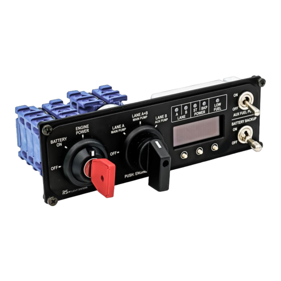
All necessary switches for Rotax iS engine operation The switching characteristics of the SCU Front Panel V2 differ from the ones for the Rotax 912 and 914 engine series. Therefore, the different engine series have an altered starting procedure. For the starting procedure, see chapter 5. - Page 4 Figure 2-1: SCU Front Panel V2 front view Figure 2-2: Front Panel V2 18.10.2022 | V1.02 Installation / Operation Manual SCU Front Panel V2...
-
Page 5: Technical Specifications
Technical Specifications The technical specifications of the SCU Front Panel V2 are listed in Table 3-1Table 3-1: Technical specification. The dimensions of the panel cut-out can be seen in Figure 3-1. SCU Front Panel V2 Mechanical 206 x 66 x 130 mm Dimensions 8.11 x 2.6 x 5.12 in... - Page 6 Figure 3-1: SCU Front Panel V2 drawing front view Figure 3-2: SCU Front Panel V2 drawing top view 18.10.2022 | V1.02 Installation / Operation Manual SCU Front Panel V2...
- Page 7 Figure 3-3: SCU Front Panel V2 drawing side view Figure 3-4: SCU Front Panel V2 drawing isometric view Installation / Operation Manual 18.10.2022 | V1.02 SCU Front Panel V2...
- Page 8 /014 0° LANE A 45° + FP Main Lane A+B 90° + FP Main PUSH 90° Lane B 135° + FP Aux Table 3-3: Lane Switch Knob switching arrangement 18.10.2022 | V1.02 Installation / Operation Manual SCU Front Panel V2...
-
Page 9: Electrical Installation
Lane Switch LANE_SEL_SW Lane B Signal 7,5 A BATTERY BACKUP BAT_BCKP Supply BATTERY BACKUP BAT_BCKP Signal EMS GND AWG 22 Aircraft GND AWG 22 Table 4-1: Start Switch Key pinout Installation / Operation Manual 18.10.2022 | V1.02 SCU Front Panel V2... - Page 10 Fuel Pump AUX Supply 10 A HIC B SIG_FUEL_PUMP_2 Fuel Pump AUX Signal 10 A HIC B CONN_STARTER_REL_SW Starter Signal HIC B SUPP_START_SWITCH Starter Supply Table 4-2: Lane Switch Knob pinout 18.10.2022 | V1.02 Installation / Operation Manual -10- SCU Front Panel V2...
- Page 11 To Main Bus To Bat. Rel. Bat. Bckp Aux FP To SCU Figure 4-1: SCU Front Panel V2 wiring diagram To SCU Front Panel out Figure 4-2: Display Panel LED connector wiring diagram Installation / Operation Manual 18.10.2022 | V1.02...
-
Page 12: Operation
Operation This chapter describes operational procedures for the SCU Front Panel V2. Starting, Aux Fuel, Battery Backup: • Start Switch in “OFF” position: both grounds “Aircraft” and “EMS” are shorted to avoid different potentials during refueling and ground handling. •... -
Page 13: Display Panel
Normal operation mode: In the first line, engine failure information is shown. In the second line engine data is displayed. With the “MCR” (Master Caution Release) button, all displayed engine failure information will be deleted. Installation / Operation Manual 18.10.2022 | V1.02 SCU Front Panel V2 -13-... - Page 14 RS Flight Systems GmbH Oberer Luessbach 29-31 82335 Berg | Germany +49 8178 8681 – 300 contact@rs-flightsystems.com www.rs-flightsystems.com SCU Front Panel V2 | Version: 1.02 © Copyright 2022 RS Flight Systems GmbH...
Need help?
Do you have a question about the SCU Front Panel V2 and is the answer not in the manual?
Questions and answers