Table of Contents
Advertisement
Quick Links
GOVERNORS
NORTH AMERICA
Low pressure gas regulators
Regolatori per gas di bassa pressione
OPERATION, MAINTENANCE
OPERATION, MAINTENANCE
AND WARNING MANUAL
AND WARNING MANUAL
Revisione A - Edizione 12/2022
Review A - Edition 12/2022
MANUALE USO,
MANUALE USO,
MANUTENZIONE
MANUTENZIONE
E AVVERTENZA
E AVVERTENZA
IT
Advertisement
Table of Contents

Related Manuals for PIETRO FIORENTINI 30051


Summary of Contents for PIETRO FIORENTINI 30051
- Page 1 GOVERNORS NORTH AMERICA Regolatori per gas di bassa pressione Low pressure gas regulators Revisione A - Edizione 12/2022 Review A - Edition 12/2022 OPERATION, MAINTENANCE OPERATION, MAINTENANCE MANUALE USO, MANUALE USO, AND WARNING MANUAL AND WARNING MANUAL MANUTENZIONE MANUTENZIONE E AVVERTENZA E AVVERTENZA...
- Page 2 PAGE INTENTIONALLY LEFT BLANK LOW PRESSURE GAS REGULATOR INTRODUCTION | REV Operation, maintenance and warning manual...
-
Page 3: Introduction
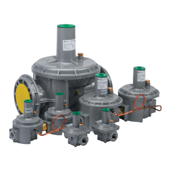
The images in this document are indicative of the product type and may differ in the details. Revision: A COPYRIGHT 2022 © PIETRO FIORENTINI S.P.A. LOW PRESSURE GAS REGULATOR INTRODUCTION REV. A Operation, maintenance and warning manual... - Page 4 PAGE INTENTIONALLY LEFT BLANK LOW PRESSURE GAS REGULATOR INTRODUCTION | REV Operation, maintenance and warning manual...
-
Page 5: Revision History
1.1 - REVISION HISTORY Revision Date Review Contents index 12/2022 First issue Tab. 1.1. LOW PRESSURE GAS REGULATOR INTRODUCTION REV. A Operation, maintenance and warning manual... -
Page 6: Table Of Contents
INDEX 1 - INTRODUCTION ........................3 1.1 - REVISION HISTORY ..........................5 2 - GENERAL INFORMATION ....................11 2.1 - MANUFACTURER IDENTIFICATION ......................11 2.2 - PRODUCT IDENTIFICATION ........................11 2.3 - REGULATORY SYSTEM ......................... 11 2.4 - WARRANTY ............................12 2.5 - RECIPIENTS, SUPPLY AND CONSERVATION OF THE MANUAL ............ - Page 7 4 - DESCRIPTION AND OPERATION ..................29 4.1 - VERSIONS, MODELS AND CONFIGURATIONS ..................29 4.1.1 - SURFACE TREATMENTS ........................30 4.2 - GENERAL DESCRIPTION ........................31 4.2.1 - ZERO VERSION DESCRIPTION ......................32 4.2.2 - OPD VERSION DESCRIPTION ......................33 4.2.3 - DUAL CUT VERSION DESCRIPTION ....................34 4.3 - OPERATION ............................
- Page 8 7 - INSTALLATION ........................63 7.1 - INSTALLATION PRE-REQUISITES ......................63 7.1.1 - ENVIRONMENTAL CONDITIONS ......................63 7.1.2 - STORAGE LONGER THAN THE MAXIMUM ALLOWABLE DURATION ..........63 7.1.3 - CHECKS BEFORE INSTALLATION ......................64 7.2 - INSTALLATION-SPECIFIC SAFETY WARNINGS ..................65 7.3 - GENERAL INFORMATION ABOUT THE LINE ..................66 7.3.1 - INSTALLATION TYPE (STANDARD/GOVAL VERSION)................67 7.3.2 - ZERO VERSION INSTALLATION ......................68 7.3.3 - RATIO VERSION INSTALLATION ......................69...
- Page 9 9 - MAINTENANCE AND FUNCTIONAL TESTING ............... 85 9.1 - GENERAL WARNINGS ........................... 85 9.2 - PERIODIC CHECKS AND VERIFICATIONS OF PROPER OPERATION ............ 86 9.2.1 - FUNCTIONAL CHECKS OF SAFETY DEVICES..................86 9.3 - TIGHTENING TORQUES ......................... 87 9.4 - STABILIZER MAINTENANCE ........................88 10 - UNINSTALLATION AND DISPOSAL .................
- Page 10 PAGE INTENTIONALLY LEFT BLANK LOW PRESSURE GAS REGULATOR INTRODUCTION | REV Operation, maintenance and warning manual...
-
Page 11: General Information
2.3 - REGULATORY SYSTEM PIETRO FIORENTINI S.P.A. with registered office in Arcugnano (Italy) - Via E. Fermi, 8/10, declares that the equipment GOVERNORS NORTH AMERICA subject of this manual is designed, manufactured, tested and controlled in accordance with the requirements of the standards: UNI EN 88-1:2016; UNI 11655:2016, UNI EN 16129:2013 as applicable. -
Page 12: Warranty
PIETRO FIORENTINI S.P.A. guarantees that the equipment has been made with the best materials, with fine workmanship and complies with the quality requirements, specifications and performance envisaged in the order. The warranty will be considered null and void and PIETRO FIORENTINI S.P.A. will not be responsible for any damage and/ or malfunctions: •... -
Page 13: Symbols Used In The Manual
2.7 - SYMBOLS USED IN THE MANUAL Symbols (some of them conforming to ANSI Z535.4) are used within the manual to: • emphasize information of relevant importance; • draw attention to the purpose of proper and safe use of the machine. Symbol Definition Symbol used to identify important warnings for operator and/or equipment safety. -
Page 14: Identification Plates Applied
It is absolutely forbidden to remove the identification plates and/or replace them with others. If, for accidental reasons, the plates are damaged or removed, the customer must inform PIETRO FIORENTINI S.p.A. The equipment and its accessories are equipped with identification plates (Id.1 to Id.7). - Page 15 Type Image OPD LABEL (MONITOR) OPD LABEL (WORKER) DUAL CUT LABEL (1ST CUT) DUAL CUT LABEL (2ND CUT) IDENTIFICATION PLATE MONITOR Tab. 2.5. LOW PRESSURE GAS REGULATOR GENERAL INFORMATION REV. A Operation, maintenance and warning manual...
-
Page 16: Identification Plates Glossary
2.8.1 - IDENTIFICATION PLATES GLOSSARY The terms and abbreviations used on the identification plate are described below: Label terminologies Description Spain Standard Russia Poland Turkey Romania Kroms Inlet pressure range max/min Regulated pressure Pç Block Block Intervention pressure ЛЗК Макс Zaw.up. -
Page 17: Measurement Unit Glossary
2.9 - MEASUREMENT UNIT GLOSSARY Measurement type Unit of measurement Description Sm³/h Standard cubic meters per hour SCFH Standard cubic feet per hour Consumption and Sm³ Standard cubic meters Volumetric flow m³/h Cubic meters per hour m³ Cubic meters Pounds per square inch psia Pounds per square inch absolute Pressure... -
Page 18: Qualified Professionals
2.10 - QUALIFIED PROFESSIONALS Qualified operators in charge of using and managing the equipment in all its phases of technical life: Professional Definition Qualified operator able to: • handle materials and equipment. • carry out all the operations necessary for a correct and safe installation of the equip- ment;... - Page 19 LOW PRESSURE GAS REGULATOR GENERAL INFORMATION REV. A Operation, maintenance and warning manual...
- Page 20 PAGE INTENTIONALLY LEFT BLANK LOW PRESSURE GAS REGULATOR GENERAL INFORMATION REV. A Operation, maintenance and warning manual...
-
Page 21: Safety
3 - SAFETY 3.1 - GENERAL SAFETY WARNINGS The equipment described in this manual is: • a device subject to pressure in pressurized systems; • normally included in systems transporting flammable gases (for example: natural gas). If the gas used is a combustible gas, the area where the equipment is installed is called a "danger zone" because there are residual risks of the formation of potentially explosive atmospheres. -
Page 22: Personal Protective Equipment
3.2 - PERSONAL PROTECTIVE EQUIPMENT Personal Protective Equipment (P.P.E.) means any equipment intended to be worn by the worker for the purpose of protecting him against one or more hazards likely to threaten his safety or health while at work. Qualified professionals, depending on the type of intervention required, will be notified of (and must use) the appropriate P.P.E. -
Page 23: Obligations And Prohibitions
For the generated noise value of the equipment and further information, please contact PIETRO FIORENTINI S.p.A. The requirement to use earmuffs or earplugs to protect the operator's hearing remains in case the noise in the equipment installation environment (depending on specific operating conditions) exceeds 85 dBA. -
Page 24: Residual Risks
2014/68/EU. In case of functional abnormalities, operation is prohibited. Contact PIETRO FIORENTINI S.p.A. immediately for necessary guidance. The equipment has no residual risk to the operator associated with its normal operation. The risks associated with the equipment and the principles adopted for their prevention are evaluated below, according to the following classification: (a) Elimination and/or reduction of risk. -
Page 25: Table Of Residual Risks Due To Pressure
3.6.1 - TABLE OF RESIDUAL RISKS DUE TO PRESSURE Effect and Risk and Hazard Event and Cause Solution and Prevention Consequence Pressurized gas a. Handling and installation by appropriate • Violent impact. outlet. • Deformation. means to avoid localized stresses. •... - Page 26 • Deterioration of • Environments with a. The user must intercept the line and exterior surfaces. Projection of metal aggressive atmo- contact PIETRO FIORENTINI S.p.A. • corrosion. and non-metal sphere. parts. Tab. 3.11. LOW PRESSURE GAS REGULATOR SAFETY | REV. A...
-
Page 27: Residual Risks Table For Potentially Explosive Atmospheres
3.6.2 - RESIDUAL RISKS TABLE FOR POTENTIALLY EXPLOSIVE ATMOSPHERES Tab. 3.12 shows the conditions that can lead to the generation of potentially explosive atmosphere by pressure regulators GOVERNORS NORTH AMERICA. The table is valid for use with natural gas with a density not exceeding 0.8; for different densities, installation conditions and environmental conditions will also need to be evaluated. - Page 28 Management measures in- Operating condi- Potentially ex- cluded in the operation, tions plosive atmo- Normative References maintenance and warning sphere manual • Pressure reduction of the section of the system in which the equip- ment is installed must take place The manual states the need to op- Decommissioning in a suitably ventilated environ-...
-
Page 29: Description And Operation
VERSIONS, MODELS AND CONFIGURATIONS The different versions of the equipment must be: • contractually established; • set up only at the establishments PIETRO FIORENTINI S.p.A. Typical versions of GOVERNORS NORTH AMERICA are listed in Tab. 4.13: Type Description Image This version has a max. inlet pressure of 0.5 bar and can be... -
Page 30: Surface Treatments
Tab. 4.13. The different models of the GOVERNORS NORTH AMERICA are identified, based on the type of connections, as shown in Tab. 4.14.: Regulator Name/Model Version Connections 30051 1/2” 30052 3/4” 30053 1” 30150 High capacity 1/2”... -
Page 31: General Description
4.2 - GENERAL DESCRIPTION The equipment is a self-operated low-pressure regulator suitable for gaseous fluids such as: • natural gas; • LPG; • propane gas; • non-corrosive gases. The balanced plug system, guarantees a constant outlet pressure value as the inlet pressure and the required flow rate change. -
Page 32: Zero Version Description
4.2.1 - ZERO VERSION DESCRIPTION The main elements of the zero version are shown in Tab. 4.16.: Pos. Description Pos. Description Inlet connection Filter cartridge (optional) Outlet connection Lower cover Balanced plug Top cap Double membrane (work and safety) Setting screw Vent threaded connection By-pass Tab. -
Page 33: Opd Version Description
4.2.2 - OPD VERSION DESCRIPTION See Section 4.2 "General Description" for the location of the main elements of the OPD version. pstream inlet pressUre ownstream oUtlet pressUre Fig. 4.3. OPD version LOW PRESSURE GAS REGULATOR DESCRIPTION AND OPERATION REV. A Operation, maintenance and warning manual... -
Page 34: Dual Cut Version Description
4.2.3 - DUAL CUT VERSION DESCRIPTION See Section 4.2 "General Description" for the location of the main elements of the Dual Cut version. 1.7 psiG pstream inlet pressUre ownstream oUtlet pressUre ressUre Fig. 4.4. Dual Cut Version LOW PRESSURE GAS REGULATOR DESCRIPTION AND OPERATION REV. -
Page 35: Operation
4.3 - OPERATION The GOVERNORS NORTH AMERICA are regulators: • self-activated; • for low pressure; • with safety membrane. In Tab. 4.17. the operation of the equipment is described in a simplified way: Phase Description The upstream pressure (A): • feeds the regulator;... -
Page 36: Opd Version Operation
4.3.1 - OPD VERSION OPERATION During normal operation, the monitor regulator (A) does not make any adjustments. If the regulating regulator (B) fails, the monitor regulator (A), through the external pressure tap (C), regulates at a safety pressure normally 70% higher than the regulator pressure (B). The action of the monitor regulator (A) keeps the operating set point below the CSA limit of 2 PSIG. -
Page 37: Dual Cut Version Operation
4.3.2 - DUAL CUT VERSION OPERATION The Dual Cut version stipulates that the regulator: • upstream (A) adjusts the pressure to 1.7 PSIG; • downstream (B) adjusts the pressure to the required outlet pressure. If the downstream regulator (B) fails, the upstream regulator (A) maintains the outlet pressure below the CSA limit of 2 PSIG. -
Page 38: Intended Use
"Intended use". Any other use of the equipment than that envisaged must be authorized in advance in writing by PIETRO FIORENTINI S.p.A. In the absence of written permission, the use is considered improper. -
Page 39: Technical/Functional Features
4.5 - TECHNICAL/FUNCTIONAL FEATURES Refer to CSA 6.22-2011/ANSI Z21.80, CSA 6.18-2002 (R2013), ANSI B109.4-1998 (R2008) for functional per- formance classification of the equipment. The main specifications are shown in Tab.4.19: Technical/functional features Standard Version 0.05 MPa Ratio Version Design pressure (DP) 0.035 MPa Zero Version Goval Version 0.1 MPa... -
Page 40: Flow Rate Coefficients
4.5.1 - FLOW RATE COEFFICIENTS In Tab. 4.20 the flow rate coefficients (Cg) of stabilizers without filter as indicated by DIN EN 334 are given: Flow rate coefficients (stabilizers without filter) Version High flow rate [mm] Nominal size [inches] 1/2” 3/4”... - Page 41 In Tab. 4.22 flow rate values are given for each model as a function of set point and inlet pressure: Flow rate in Scfh with filter (flow rate without filter in brackets) Operating inlet pressure Set point Model outlet pressure 14”WC 1 psig 2 psig...
- Page 42 In Tab. 4.23 flow rate values are given for each model as a function of set point and inlet pressure: Flow rate in Scfh with filter (flow rate without filter in brackets) Operating inlet pressure Set point Model outlet pressure 14”WC 1 psig 2 psig...
- Page 43 In Tab. 4.24 flow rate values are given for each model as a function of set point and inlet pressure: Flow rate in Scfh with filter (flow rate without filter in brackets) Operating inlet pressure Set point Model outlet pressure 14”WC 1 psig 2 psig...
-
Page 44: Safety Devices
4.6 - SAFETY DEVICES To avoid tripping of safety devices during normal service (when the utility has no anomalies), flushing purges of the down- stream line should not be carried out with the reducer installed. 4.6.1 - SAFETY MEMBRANE Tripping of the safety membrane (A) results in replacement of the regulator. The safety membrane (A) is a device capable of limiting the leakage of gas into the atmosphere if the working membrane (B) ruptures. -
Page 45: Vent Limiter
4.6.2 - VENT LIMITER The vent limiter should not be used outdoors or in environments exposed to the weather. The vent limiter (A) is: • designed in accordance with ANSI Z21.80a-2005 requirements; • optional. The vent limiter (A) prevents vent piping to the outside when stabilizer use is planned in enclosed rooms or spaces where limiting the amount of gas leakage due to membrane malfunction is critical. -
Page 46: Pressure Tap
4.6.3 - PRESSURE TAP The pressure tap integrated (A) to the regulator is required for field verification of safety devices: Fig. 4.10. Standard pressure taps LOW PRESSURE GAS REGULATOR DESCRIPTION AND OPERATION REV. A Operation, maintenance and warning manual... -
Page 47: Procedure For Use With Standard Pressure Tap
4.6.3.1 - PROCEDURE FOR USE WITH STANDARD PRESSURE TAP The maximum use pressure for the standard pressure tap is 0.5 bar. To use the standard pressure tap (A), proceed as shown in Tab.4.25: Step Operation Unscrew the locking screw (B). Fit the rubber hose on the tang (C) making sure that the connection ensures tightness. - Page 48 PAGE INTENTIONALLY LEFT BLANK LOW PRESSURE GAS REGULATOR DESCRIPTION AND OPERATION REV. A Operation, maintenance and warning manual...
-
Page 49: Transport And Handling
5 - TRANSPORT AND HANDLING 5.1 - SPECIFIC WARNINGS FOR TRANSPORT AND HANDLING The transport and handling activities, in compliance with the regulations in force in the country of destina- tion of the equipment, must be carried out by personnel: •... -
Page 50: Packaging And Fastening Systems Used For Transport
• immediately report to PIETRO FIORENTINI S.p.A. any damage found. PIETRO FIORENTINI S.p.A. is not liable for damage to property or persons caused by accidents caused by failure to comply with the instructions given in this manual. In Tab. 5.27. the types of packaging used are described: Ref. -
Page 51: Physical Characteristics Of Stabilizer With And Without Filter
5.2 - PHYSICAL CHARACTERISTICS OF STABILIZER WITH AND WITHOUT FILTER Fig. 5.12. Physical characteristics of stabilizer with and without filter Dimensions Weight Model [Lbs] [in] [in] [NPT] [in] [in] [in] [in] 31051 1/2” NPT 4.09 1/2” 5.59 3.78 1.54 31052 3/4"... -
Page 52: Physical Characteristics Of The Zero Version
5.2.1 - PHYSICAL CHARACTERISTICS OF THE ZERO VERSION Fig. 5.13. Physical characteristics of the Zero version Dimensions Weight Model [Lbs] [in] [in] [NPT] [NPT] [in] [in] L150-R150-Y150-V150 1/2” 4.72 1/2” 67.32 8.82 L151-R151-Y151-V151 3/4” 4.72 3/4” 67.32 8.82 L152-R152-Y152-V152 1” 4.72 1”... -
Page 53: Physical Characteristics Of The Ratio Version
5.2.2 - PHYSICAL CHARACTERISTICS OF THE RATIO VERSION Fig. 5.14. Physical characteristics of the Ratio version Dimensions Weight Model [Lbs] [in] [in] [NPT] [NPT] [in] [in] L150-Y150 1/2” 4.72 1/2” 71.85 11.02 L151-Y151 3/4” 4.72 3/4” 71.85 11.02 L152-Y152 1” 4.72 1”... -
Page 54: Physical Characteristics Of The Opd And Dual Cut Versions
5.2.3 - PHYSICAL CHARACTERISTICS OF THE OPD AND DUAL CUT VERSIONS Fig. 5.15. Physical characteristics of the OPD and Dual Cut versions Dimensions Weight Model [Lbs] [in] [in] [NPT] [in] [in] [in] [in] 31051 1/2” NPT 8.46 5.59 3.78 3.25 31052 3/4"... -
Page 55: Method For Anchoring And Lifting The Equipment
5.3 - METHOD FOR ANCHORING AND LIFTING THE EQUIPMENT The use of lifting equipment (if required) for unloading, transporting and handling of packages is reserved only for qualified operators who have received adequate training and instruction (holding the appropriate license when regulations in the country of installation require it) and knowledgeable: •... -
Page 56: Forklift Handling Method
5.3.1 - FORKLIFT HANDLING METHOD It is forbidden to: • pass under suspended loads; • move the load over the personnel working in the site/plant area. On forklift trucks it is forbidden to: • transport passengers; • lift people. In case the cardboard boxes (single or multiple) are supported by a pallet, proceed as shown in Tab.5.32: Step Operation Image... - Page 57 Step Operation Image Sollevare lentamente il carico di qualche decina di centimetri e veri carne la stabilità facendo attenzio- Inclinare il montante all’indietro (verso il posto guida) per avvantaggiare il momento ribaltante e Adeguare la velocità d ne che il baricentro del carico sia posizionato al centro delle forche di sollevamento. garantire una maggiore stabilità...
-
Page 58: Unpacking
• do not perform the installation operations; • contact PIETRO FIORENTINI S.p.A. communicating the data shown on the identification plate of the equipment. 5.4.1 - PACKAGING DISPOSAL Separate the various materials making up the packaging and dispose of them in compliance with the reg- ulations in force in the country of installation. -
Page 59: Storage And Environmental Conditions
5.5 - STORAGE AND ENVIRONMENTAL CONDITIONS Protect the regulator from blows and shocks, even accidental, until installation. The minimum environmental conditions expected if the equipment is to be stored for a long period are given in Tab.5.40. Compliance with these conditions guarantees the stated performance: Terms and conditions Data Maximum storage period... - Page 60 PAGE INTENTIONALLY LEFT BLANK LOW PRESSURE GAS REGULATOR TRANSPORT AND HANDLING REV. A Operation, maintenance and warning manual...
-
Page 61: Commissioning/Maintenance Equipment
6 - COMMISSIONING/MAINTENANCE EQUIPMENT 6.1 - EQUIPMENT LIST Installation/commissioning/maintenance equipment use • Installer. Operator qualification • Specialized technician/Maintenance technician. The PPE listed in this chart relates to the risk associated with the equipment. PPE required For the PPE required to protect against risks associated with the workplace, installation or operating conditions, refer to: •... - Page 62 PAGE INTENTIONALLY LEFT BLANK LOW PRESSURE GAS REGULATOR REV. A COMMISSIONING/MAINTENANCE EQUIPMENT Operation, maintenance and warning manual...
-
Page 63: Installation
7 - INSTALLATION 7.1 - INSTALLATION PRE-REQUISITES 7.1.1 - ENVIRONMENTAL CONDITIONS For the safe use of the equipment, respecting the permitted environmental conditions, follow the data on the plate applied and any accessories (refer to paragraph 2.8 "Identification plates applied"). The equipment should be installed away from the weather and direct sunlight. -
Page 64: Checks Before Installation
7.1.3 - CHECKS BEFORE INSTALLATION In relation to its design pressure (DP), the equipment does not require any additional upstream safety device to protect against possible overpressure when, for the upstream reduction station, the maximum downstream incidental pressure MIPd ≤ 1.1 DP MIPd = maximum value of downstream incidental pressure (for more information see UNI EN 12186:2014). -
Page 65: Installation-Specific Safety Warnings
The installer must: • use the fittings and gaskets supplied with the equipment by PIETRO FIORENTINI S.p.A. • secure the swivels (when provided) according to the tightening torques specified in the standards: NF E29-533: 2014 and NF E29-536: 2017. -
Page 66: General Information About The Line
7.3 - GENERAL INFORMATION ABOUT THE LINE The equipment must be installed on the line respecting: • the direction of gas flow as indicated by the arrow on the equipment itself; • the correct mounting position: Fig. 7.16. Correct mounting position of the Standard/Goval versions When the device is used in gas pressure reduction stations, it must be installed at least according to the requirements of UNI EN 12186:2014 or UNI EN 12279:2007. -
Page 67: Installation Type (Standard/Goval Version)
7.3.1 - INSTALLATION TYPE (STANDARD/GOVAL VERSION) The following must be present in the standard installation of the equipment and the Goval version: Pos. Description Pressure regulator. Shut-off valve upstream of the regulator (A). Shut-off valve downstream of the regulator (when required). Burner. -
Page 68: Zero Version Installation
7.3.2 - ZERO VERSION INSTALLATION When installing the equipment in the Zero version, there must be: Pos. Description Filter Solenoid valve Zero version regulator Motor Tab. 7.39. Fig. 7.18. Zero version installation examples LOW PRESSURE GAS REGULATOR INSTALLATION REV. -
Page 69: Ratio Version Installation
7.3.3 - RATIO VERSION INSTALLATION When installing the equipment in the Ratio version, there must be: Pos. Description Filter Ratio version regulator ratio 1:1 Solenoid valve Solenoid valve Tab. 7.40. Fig. 7.19. Ratio version installation examples LOW PRESSURE GAS REGULATOR INSTALLATION REV. -
Page 70: Installation Type (Opd/Dual Cut Version)
7.3.4 - INSTALLATION TYPE (OPD/DUAL CUT VERSION) When installing the OPD and Dual Cut versions, there must be: Pos. Description Pressure regulator. Shut-off valve upstream of the regulator (A). Shut-off valve downstream of the regulator (when required). Burner. Tab. 7.41. Fig. -
Page 71: Installation Procedures
UNI EN ISO 228-1). Tab. 7.43. The warranty will be considered void and PIETRO FIORENTINI S.p.A. will not be responsible for any dam- age and/or malfunction if the fittings used during installation are not those supplied. LOW PRESSURE GAS REGULATOR INSTALLATION REV. -
Page 72: Post-Installation Indications
Tab. 7.44. The pressure of the relief valve does not require to be adjusted in the field. Contact PIETRO FIORENTINI S.p.A. for further requirements. It is prohibited to make unauthorized changes on the equipment without permission from PIETRO FIORENTINI S.p.A. -
Page 73: Standard Version Adjustments
7.5.1 - STANDARD VERSION ADJUSTMENTS In case it is necessary, for standard regulators with or without block valves, to change the setting values in order to in- crease or decrease the operating pressure, proceed as shown in Tab.7.45: Step Operation Equipment required Remove the top cap (A) of the regulator. -
Page 74: Zero Version Adjustments
7.5.2 - ZERO VERSION ADJUSTMENTS In case it is necessary to change the calibration values of the Zero version regulator in order to increase or decrease the zero pressure, proceed as shown in Tab.7.46: Step Operation Equipment required Remove the top cap (A) of the regulator. Turn the ring nut (B): •... -
Page 75: Ratio Version Adjustments
7.5.3 - RATIO VERSION ADJUSTMENTS The ratio regulator is driven by air line pressure. The gas outlet pressure is adjusted 1:1 to the control air pressure. • You can vary the power of the burner by acting on the air regulator. •... -
Page 76: Opd Version Adjustments
7.5.4 - OPD VERSION ADJUSTMENTS In case it is necessary, change the calibration values of the OPD version regulator, proceed as shown in Tab.7.48: Step Operation Equipment required Remove the top cap (A) of the downstream regulator. Turn the ring nut (B) of the downstream regulator: •... -
Page 77: Dual Cut Version Adjustments
7.5.5 - DUAL CUT VERSION ADJUSTMENTS In case it is necessary, change the calibration values of the Dual Cut version regulator, proceed as shown in Tab.7.49: Step Operation Equipment required Remove the top cap (A) of the downstream regulator. Turn the ring nut (B) of the downstream regulator: •... - Page 78 PAGE INTENTIONALLY LEFT BLANK LOW PRESSURE GAS REGULATOR INSTALLATION REV. A Operation, maintenance and warning manual...
-
Page 79: Commissioning
8 - COMMISSIONING 8.1 - GENERAL WARNINGS 8.1.1 - SAFETY REQUIREMENTS FOR COMMISSIONING During commissioning, the risks posed by possible discharges of flammable or noxious gases into the atmosphere must be assessed. In the case of installation on distribution networks for natural gas, the risk of explosive mixture (gas/air) formation inside the pipes should be considered if an inerting procedure of the line is not adopted. -
Page 80: Preliminary Procedures For Commissioning
8.3 - CALIBRATION OF SAFETY DEVICES The equipment is regulated at the manufacturing plants of PIETRO FIORENTINI S.p.A. It is prohibited to tamper with or make unauthorized changes on the equipment without permission from PIETRO FIORENTINI S.p.A. -
Page 81: Commissioning Of The Standard Version Regulator
8.4.1 - COMMISSIONING OF THE STANDARD VERSION REGULATOR For commissioning the regulator with and without block valve (A), proceed as shown in Tab. 8.51.: Step Operation Partially open the downstream vent tap when present. Slowly open upstream shutoff devices (e.g. OPSO block valve, valve (B), etc...). Wait for the downstream pressure to stabilize at the spring setting P2 indicated on the plate. -
Page 82: Commissioning Of The Zero Version Regulator
8.4.2 - COMMISSIONING OF THE ZERO VERSION REGULATOR For commissioning the Zero (C) version regulator, proceed as shown in Tab. 8.52.: Step Operation Partially open the downstream vent tap when present. Slowly open upstream shutoff devices (e.g., solenoid valves, OPSO block valve, etc.). Wait for the downstream pressure to stabilize at the spring setting P2 indicated on the plate. -
Page 83: Commissioning Of The Ratio Version Regulator
8.4.3 - COMMISSIONING OF THE RATIO VERSION REGULATOR To commission the Ratio (B) version regulator, proceed as shown in Tab. 8.53.: Step Operation Partially open the downstream vent tap when present. Slowly open upstream shutoff devices (e.g., solenoid valves, OPSO block valve, etc.). Wait for the downstream pressure to stabilize at the spring setting P2 indicated on the plate. -
Page 84: Commissioning Of The Opd And Dual Cut Version Regulator
8.4.4 - COMMISSIONING OF THE OPD AND DUAL CUT VERSION REGULATOR For commissioning the OPD and Dual Cut (A) versions, proceed as shown in Tab. 8.54.: Step Operation Partially open the downstream vent tap when present. Slowly open upstream shutoff devices (e.g. OPSO block valve, valve (B), etc...). Wait for the downstream pressure to stabilize at the spring setting P2 indicated on the plate. -
Page 85: Maintenance And Functional Testing
GENERAL WARNINGS The equipment does not have periodic checks and maintenance procedures. No liability related to personal injury or property damage can be attributed to PIETRO FIORENTINI S.p.A. for interventions performed without the authorizations. In case of doubts or functional abnormalities, operation is prohibited. Contact PIETRO FIORENTINI S.p.A. -
Page 86: Periodic Checks And Verifications Of Proper Operation
9.2 - PERIODIC CHECKS AND VERIFICATIONS OF PROPER OPERATION Checks and inspections should be carried out only by licensed technicians. Periodic checks and inspections Operator qualification • Commissioning technician. The PPE listed in this chart relates to the risk associated with the equipment. PPE required For the PPE required to protect against risks associated with the workplace, installation or operating conditions, refer to:... -
Page 87: Tightening Torques
Step Operation Close the downstream pressure tap (Step 3). Open the shut-off valve closed in Step 1. Perform commissioning as described in Section 7.4. Check for leaks at the closed pressure tap at Step 6. Tab. 9.57. 9.3 - TIGHTENING TORQUES Refer to the following standards for tightening torques for swivels: NF E29-533: 2014 and NF E29-536: 2017. -
Page 88: Stabilizer Maintenance
9.4 - STABILIZER MAINTENANCE Fig. 9.30. Stabilizer maintenance LOW PRESSURE GAS REGULATOR MAINTENANCE AND FUNCTIONAL TESTING REV. A Operation, maintenance and warning manual... - Page 89 The reported maintenance procedures apply to: • the entirety of GOVERNORS NORTH AMERICA except the PF400 and PF400 Dual Cut versions. In case of failure, when maintenance is not planned, refer to the authorized dealer; • both regulators (upstream and downstream) of the OPD and Dual Cut versions. Step Operation Remove the cap (B) from the top cover (I).
- Page 90 Stabilizer maintenance LOW PRESSURE GAS REGULATOR MAINTENANCE AND FUNCTIONAL TESTING REV. A Operation, maintenance and warning manual...
- Page 91 Step Operation Insert the balancing membrane (T). • The O-ring of the balancing membrane (T) must be inside the groove. • Check the cleanliness of the groove. Insert the balancing membrane lock disk (U). Be careful to center all holes present. Insert and fasten screws (Q) according to the torque values of current guidelines and regulations.
- Page 92 Stabilizer maintenance LOW PRESSURE GAS REGULATOR MAINTENANCE AND FUNCTIONAL TESTING REV. A Operation, maintenance and warning manual...
- Page 93 Step Operation Insert the top cover (I). The vent hole is perpendicular to the outlet pipe. Insert and fasten screws (H) according to the torque values of current guidelines and regulations. NOTICE! Grease the holes before inserting the screw. Insert the calibration spring (E). Position the spring press (D).
- Page 94 PAGE INTENTIONALLY LEFT BLANK LOW PRESSURE GAS REGULATOR MAINTENANCE AND FUNCTIONAL TESTING REV. A Operation, maintenance and warning manual...
-
Page 95: Uninstallation And Disposal
10 - UNINSTALLATION AND DISPOSAL 10.1 - GENERAL SAFETY WARNINGS Ensure that there are no effective ignition sources in the work area set up for equipment de-installation and/or disposal. Before proceeding with uninstallation and disposal operations, ensure that the equipment is secured by disconnecting it from all power supplies. -
Page 96: Information Needed In Case Of New Installation
10.4 - INFORMATION NEEDED IN CASE OF NEW INSTALLATION In case the equipment after uninstallation is to be reused, refer to chapters: “Installation” and “Commis- sioning”. 10.5 - DISPOSAL INFORMATION • Proper disposal avoids harm to humans and the environment and promotes the reuse of valuable raw materials. -
Page 97: Calibration Tables
When the value shown on the regulator plate is equal to the minimum or maximum value of a spring listed in the tables below, the spring in the regulator is the one with the minimum range value equal to the cali- bration value in the data plate. 30051/52/53 30150/51/52 30153/54/54F... - Page 98 TM0061USA...
Need help?
Do you have a question about the 30051 and is the answer not in the manual?
Questions and answers