
Subscribe to Our Youtube Channel
Related Manuals for OETIKER EPC 01


Summary of Contents for OETIKER EPC 01
- Page 1 OETIKER EPC 01 Instruction manual Translation of the original OETIKER Schweiz AG instruction manual Spätzstrasse 11 Part no. 08905306 CH-8810 Horgen Issue 221129_V02_a Switzerland...
-
Page 2: Table Of Contents
......... . 9 Using the ePC 01 via an external control system......10 Modifications, changes . - Page 3 01 ....... . 26...
- Page 4 10.4.4 Have the ePC 01 unit repaired ....... . 69...
- Page 5 OETIKER EPC 01 Table of ConTenTs 11.3 Troubleshooting measures for error messages ......71 11.3.1 fixing errors of the «system»...
-
Page 6: Information About This Manual
The Trigger Unit of the elK 02 cannot be used as a hand-held tool. • The Trigger Unit of the elK 02 can be used with the ePC 01, provided it is operated in semi-automatic or fully automatic mode. •... -
Page 7: Basic Safety Instructions
• low-profile clamps with high process reliability. • The ePC 01 must be used only as specified as intended use and when it is in a technically safe and fault-free condition. • Intended use also covers observance of this instruction manual and compliance with the technical data. -
Page 8: Special Safety Instructions
► Depressurize all air-operated plant components and equipment. ► Please operate the ePC 01 between 4 bar to 10 bar (recommended: 6 bar). Do not operate the ePC 01 at pressures greater than 10 bar. ► ensure that the vent holes on the pincer body are clear. -
Page 9: Safe Working Methods
OETIKER EPC 01 basIC safeTy InsTRUCTIons Safe working methods ► before each start of production, check the ePC 01 for visible damage and ensure that it is operated only when in perfect condition. ► Report deficiencies to the supervisor immediately. –... -
Page 10: Using The Epc 01 Via An External Control System
• If you have any questions about integration, contact oeTIKeR. Modifications, changes If the seal on the ePC 01 is damaged or is removed without authorization, oeTIKeR will not accept any warranty claims. ► Do not modify the ePC 01 without the consent of oeTIKeR. any modification excludes liability on the part of oeTIKeR for any resulting damage. -
Page 11: Maintenance Tasks
Regularly check that the pincer head and closure mechanism are working properly. If cracks and fractures occur, replace the relevant components. ► Complex maintenance work involving opening the ePC 01 must be carried out exclusively by a local oeTIKeR service Center (see chapter 14). 2 11 Signs on the EPC 01... -
Page 12: Nameplates
OETIKER EPC 01 basIC safeTy InsTRUCTIons 2 11 2 Nameplates Fig 2: Nameplates (left: control unit, right: pincer) www.oetiker.com 08905306 Issue 11.22... -
Page 13: Structure And Description
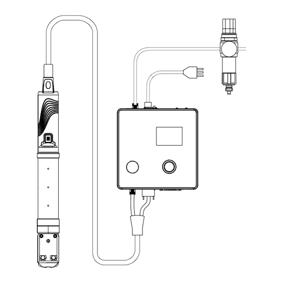
OETIKER EPC 01 sTRUCTURe anD DesCRIPTIon Structure and description Overall EPC 01 system Structure Fig 3: Structure of the overall EPC 01 system Pincer holder (recommended, plastic) Compressed air filter Pincer Compressed air reservoir Hybrid hose service unit Control Unit 10. PC Compressed air supply line 11. -
Page 14: Control Unit
DesCRIPTIon Description The oeTIKeR ePC 01 is an electro-pneumatic system for closure of clamps and low-profile clamps. The compo- nents of the system are connected to each other via compressed air hoses (3, 5). The compressor / compressed air supply (12) generates compressed air which flows to the service unit (9). To protect the entire system from overpressure, the service unit (9) reduces the air pressure to the defined range of pressure. - Page 15 OETIKER EPC 01 sTRUCTURe anD DesCRIPTIon Item Designation Description / Use Interface for communication with the PC software ethernet Interface for communication with the PC software Rotary pushbutton operating the menu of the Control Unit Displaying the menus of the Control Unit...
-
Page 16: Pincer
(con- sultation with oeTIKeR required). after the pincer head has been changed, a pincer test is required. The pincer head can be changed as required within the following 3 groups: •... -
Page 17: Cal 01
The sKs0x sensor (2) is mounted on the pincer head. The measured force can either be transferred to the PC software or directly to the Control Unit. The Cal 01 is a stand-alone device available from oeTIKeR. The function of the device can be found in the corre- sponding Instruction manual. -
Page 18: Process Description
PRoCess DesCRIPTIon Process description Process flow The ePC 01 is used for professional and reliable closure of oeTIKeR clamps and low-profile clamps. To do this, an ear or the closure hook of the low-profile clamp (1) is inserted between the pincer jaws (2). -
Page 19: Closing Modes
The stroke priority closure function is used to close low-profile clamps. because the performance of a low-profile clamp is guaranteed only when the hook is engaged, the ePC 01 closes up to a certain gap value at which the engagement of the low-profile clamp is ensured. -
Page 20: Schnappi
OETIKER EPC 01 PRoCess DesCRIPTIon 4 2 3 Schnappi With this closure function, closure takes place at a defined closure force (force priority closure), whereby the control unit detects when the hook has been passed over and stops the crimping process. This ensures that the material is not stressed excessively. -
Page 21: Hold Or Detect
OETIKER EPC 01 PRoCess DesCRIPTIon 4 3 2 Hold or detect only one option can be selected and used at a time. Hold The clamp is held in place using a little force between the pincer jaws in order to pre-position and hold in place the parts being crimped. -
Page 22: Contact
OETIKER EPC 01 PRoCess DesCRIPTIon Detect The detection function identifies a second closure of the same clamp or low-profile clamp and reports the proce- dure as noK. The detection function requires that a specified force must be achieved for a specified gap. If the clamp had already been closed the force at the gap will not be reached, and the closure process is canceled. -
Page 23: Pincer Test
PRoCess DesCRIPTIon Pincer test The pincer functions as a crimping tool, which is stressed and subjected to wear during use. oeTIKeR therefore strongly recommends that the pincer is regularly calibrated using the pincer test. The pincer test should be per- formed at the beginning of a shift and must be performed after changing the pincer jaws or the pincer head. -
Page 24: Friction Test
In the first stage of the two-stage force test, a low force is produced in the pincer. Providing a force correction is needed only if the actual force value measured with Cal 01 is outside of the range displayed on the ePC 01. -
Page 25: Structure And Connection
(standard: 3 m, optional: 6 m, 9 m, 12 m) ► oeTIKeR el (T) pincer installed in a mounting fixture float. The floating bearing facilitates the closure process of the clamps and low-profile clamps. appropriate devices are available as options. -
Page 26: Setting Up And Connecting The Epc 01
01 bracket Control Unit Proceed as follows for wall mounting: – Measure the oblong or round holes of the ePC 01 bracket. – Drill 4 holes in the wall accordingly. Mount the ePC 01 back plate with four M6 screws. - Page 27 OETIKER EPC 01 sTRUCTURe anD ConneCTIon Pincer and hybrid hose CAUTION Damage to the pincer and the hybrid hose due to improper assembly! ► Do not clamp the pincer at the cylinder tube of the pincer body (only the Ho 7000 version can be clamped at the reinforced point at the center of the pincer body).
- Page 28 ► for the variant with a light-current equipment plug ensure the following: – Connect the ePC 01 only to power supply systems fitted with a ground fault circuit interrupter / GfCI – Use only the power cord supplied with the device and do not exchange it ►...
-
Page 29: Initial Commissioning
OETIKER EPC 01 sTRUCTURe anD ConneCTIon Initial commissioning ePC 01 set up and connected. Documents supplied with licensing code. start the PC-software on the PC. switch on Control Unit. acknowledge error, if present. Connect PC to an interface of Control Unit (e.g. Usb). -
Page 30: Working With The Epc 01
Control Unit, switch the On/Off switch on. for the 24 V DC variant, switch on the ePC 01 at the separate voltage supply (detailed information on this see chapter 13.2). -
Page 31: Proceed With The Closure Functions
Proceed with the pincer test (see chapter 4.4). Insert one ear of each oeTIKeR clamp (1) into the clamping area on the pincer head (2). for low-profile clamps: Position the pincer jaws on the closure hooks of the low-profile clamp. -
Page 32: Epc 01 Feedback
Proceed with the pincer test (see chapter 4.4). Set EPC 01 out of operation If the ePC 01 is not going to be used for an extended period of time it must be taken out of operation and then stored. ePC 01 switched off. -
Page 33: Epc 01 Menu
OETIKER EPC 01 ePC 01 MenU EPC 01 menu User level The access rights for the settings and functions in the menu depend on the user level. a role description of the personnel can be found in the personnel qualification (see chapter 2.9). -
Page 34: Menu Structure
Menu structure 7 3 1 Overview The start menu appears when the ePC 01 is switched on. starting from the start menu, the rotary pushbutton can be used to navigate to the next menu level. for the complete structure, refer to the graphical menu structure (see chapter 7.3.2). -
Page 35: Structure
OETIKER EPC 01 ePC 01 MenU 7 3 2 Structure Fig 18: Structure of the menu Issue 11.22 08905306 www.oetiker.com... - Page 36 OETIKER EPC 01 ePC 01 MenU Fig 19: Structure of the menu (here: Pincer Test) www.oetiker.com 08905306 Issue 11.22...
-
Page 37: Pc-Software
Usb-drives will open auto- matically. USB driver If it is necessary to update the ePC 01 firmware, select and install the appropriate driver. for 64-bit systems, execute the driver dpinst_amd64 exe and install it. see hint during installation. -
Page 38: Structure And Elements Of The Pc Software
Unit can be easily selected. The set IP address cannot be sent to the Control Unit. • Roles configuration. Instruction manual opens the instruction manual. about View information about software and oeTIKeR. log In • User login and logout. • Password for user role «line Manager»: easy! •... - Page 39 Press the + button to increase the value the value • Press the - button to decrease the value Input field enter characters or values (example here: EPC 01). Check box • Check the box to select the function. •...
-
Page 40: Basic Operation
OETIKER EPC 01 PC-sofTWaRe Basic operation 8 4 1 Start PC software Monitor and PC are switched on. operating system is started. ► on the desktop, click the shortcut to the PC software. The PC software is started and the start page appears. -
Page 41: Menu Control Unit
OETIKER EPC 01 PC-sofTWaRe Control Unit menu navigation: Home > Control Unit 8 5 1 Overview of the menu structure Menu page Sub-menu page Control Unit Connect to Control Unit Read – send – Measure start measuring stop measuring Clear measurements Pincer test... -
Page 42: Read Data Set
OETIKER EPC 01 PC-sofTWaRe 8 5 3 Read data set navigation: Home > Control Unit > Read Fig 23: Read menu on the Read menu page, data from the Control Unit are read into the PC software. either the data are read in as a new data set or an existing data set is overwritten in the process. -
Page 43: Measure
OETIKER EPC 01 PC-sofTWaRe 8 5 5 Measure navigation: Home > Control Unit > Measure Fig 25: Measure menu on the Measure menu page, all log entries relevant for closure are displayed as an overview. This is required for the validation phase. Measurements can be started or stopped. existing entries can be erased. -
Page 44: Pincer Test
OETIKER EPC 01 PC-sofTWaRe 8 5 6 Pincer test navigation: Home > Control Unit > Pincer Test Fig 26: Pincer test menu on the Pincer Test menu page, the pincer test is requested by pressing the Request button. Work using the pin- cer must be interrupted in order to perform the pincer test. -
Page 45: Execute Commands
OETIKER EPC 01 PC-sofTWaRe 8 5 7 Execute commands navigation: Home > Control Unit > Commands Fig 27: Commands menu on the Commands menu page, the following commands can be executed in the corresponding sub-menus: • Deleting a log file • Updating firmware •... -
Page 46: Local Dataset Menu
OETIKER EPC 01 PC-sofTWaRe Updating the firmware language navigation: Home > Control Unit > Commands > Update firmware Language Fig 31: Update firmware language sub-menu on the Update firmware language sub-menu page the firmware language is updated. Press the Browse button to select the language firmware update file. once the correct file has been selected, the update is started by pressing the Update firmware language button. -
Page 47: Edit Local Dataset
OETIKER EPC 01 PC-sofTWaRe Menu page Sub-menu page Functions sequence Data set • save • send to Control Unit Clamp data sequence • open single view • • new from existing • Delete Control Unit settings General – Closing –... -
Page 48: Importing The Local Dataset
OETIKER EPC 01 PC-sofTWaRe 8 6 3 Importing the local data set navigation: Home > Local data set > Import Fig 34: Import sub-menu local data sets are imported, e.g. even from an external device, using the Import sub-menu page. The data set file is selected via the Browse button. -
Page 49: Exporting The Local Dataset
OETIKER EPC 01 PC-sofTWaRe 8 6 4 Exporting the local data set navigation: Home > Local data set > Export Fig 35: Export sub-menu In order to import the file e.g. to another PC, the local data sets are exported using the Export sub-menu page. - Page 50 OETIKER EPC 01 PC-sofTWaRe Clamping data single view navigation: Home > Local data set > Clamping data > Clamp data single view Fig 37: Clamp data single view sub-menu once the Clamp data single view has been opened, the closure data set is edited as required.
-
Page 51: Edit Sequence
OETIKER EPC 01 PC-sofTWaRe 8 6 6 Edit sequence navigation: Home > Local data set > Sequence Fig 38: Sequence sub-menu on the Sequence sub-menu page, all sequences are displayed as an overview. The sequence to be edited is selected here, and then, depending on the requirements, selected as follows opened, newly created, duplicated or deleted. - Page 52 OETIKER EPC 01 PC-sofTWaRe Clamping data sequence single view navigation: Home > Local data set > Sequence > Clamp data sequence single view Fig 39: Sequence sub-menu once the Clamp data sequence single view sub-menu page has been opened, the sequence is edited as need- To create or edit a sequence, the clamping data are selected according to the desired sequence in the drop-down menu.
-
Page 53: Edit The Control Unit Settings
OETIKER EPC 01 PC-sofTWaRe 8 6 7 Edit the Control Unit settings navigation: Home > Local data set > Settings Control Unit Edit general settings navigation: Home > Local data set > Settings Control Unit > General Fig 40: General sub-menu The following general settings are made on the General sub-menu page:... - Page 54 If the start signal is sent from a external control, this must be selected here. With this option, the safety valve must be actively mechanically locked by a lock- ing ring recommended by oeTIKeR (see chapter 9). • START button on the Trigger Unit and external control jointly Input control select the source of the start signal.
- Page 55 OETIKER EPC 01 PC-sofTWaRe Element Description of the setting Trigger mode select starting the closure process. • Tip (press start button until closure is completed, when released the pincer opens and the process is aborted). • Impulse (a short pulse on the start button triggers complete closure).
- Page 56 OETIKER EPC 01 PC-sofTWaRe Edit settings for closure feedback navigation: Home > Local data set > Settings Control Unit > Closure feedback Fig 42: Closure feedback sub-menu The settings for feedback from the Control Unit are made on the Closure feedback sub-menu page.
- Page 57 Compatibility mode sub-menu page the same process times of the oeTIKeR elK 02 can be readjusted for force priority and gap priority closures. This function is selected only in the event that an elK 02 is replaced or after consultation with oeTIKeR. The qual- ity of the closures is maintained and there are no disadvantages.
-
Page 58: View Statistics
OETIKER EPC 01 PC-sofTWaRe 8 6 8 View statistics navigation: Home > Local data set > Statistic Fig 45: Statistic sub-menu on the Statistic sub-menu page all closures per pincer are displayed. In addition, the Control Unit counts all clo- sures and all noK closures. -
Page 59: View Log File
OETIKER EPC 01 PC-sofTWaRe 8 6 9 View log file navigation: Home > Local data set > Log data Fig 46: Log data sub-menu on the Log data sub-menu page all actions of the Control Unit are stored as log files, provided that the log files have been read in (see chapter 8.5.3). -
Page 60: View Licensed Functions
OETIKER EPC 01 PC-sofTWaRe 8 6 10 View Licensed Functions navigation: Home > Local Data set > Licensed features Fig 47: Licensed features sub-menu The rights conferred by the license that is used are displayed on the Licensed features sub-menu page. ac- tive rights are marked with a check mark. license violations are displayed in the right-hand column. -
Page 61: Operate The Epc 01 Via An External Control Unit (Plc)
If you have any questions about the integration, please contact oeTIKeR. Description of the integration for semi/fully automatic mode 9 1 1 Instruction of Incorporation The standard version (delivery condition) of the ePC 01 is designed as a complete machine with valid Ce confor- mity. NOTICE... -
Page 62: Maintenance And Repair
Use only original spare parts from oeTIKeR. • Maintenance work may be performed only once the ePC 01 has been disconnected from the power supply. • following initial commissioning, the ePC 01 unit should be cleaned daily or weekly, depending on the degree of soiling. -
Page 63: Perform Maintenance According To The Maintenance Schedul
Clean the ePC 01 exclusively with water. ► Do not use aggressive cleaning agents. In the event of minor contamination, clean the ePC 01 with a dry cloth. In the event of heavy soiling, clean the ePC 01 with a damp cloth. Completion of maintenance (see chapter 10.2.2). -
Page 64: Checking And Changing The Pre-Filter
Completion of maintenance (see chapter 10.2.2). 10 3 4 Have the pincer and pincer head serviced (recommended) oeTIKeR recommends that the pincer and the pincer head are sent to the local oeTIKeR service Center (see chapter 14) for servicing after the specified interval. a counter is integrated in the Trigger Unit of the clamp, which after 250,000 closures issues a warning to the Con- trol Unit that maintenance is due. - Page 65 OETIKER EPC 01 MaInTenanCe anD RePaIR NOTICE each pincer body is compatible with different pincer heads. The type designations can be found in the tool catalog. Scope of supply of a pincer head set • lip seal (1) • Piston guide band with wedge piston (2) •...
-
Page 66: Aligning The Pincer Head
OETIKER EPC 01 MaInTenanCe anD RePaIR 10 4 2 Aligning the pincer head WARNING Crush hazard when aligning the pincer head! fingers can be crushed or severed when the sTaRT button is pressed or when a start is initiated by an external control. - Page 67 CAUTION Damage to the pincer from third-party parts! ► only use original oeTIKeR pincer jaws. only fit the designated pincer jaws type in the pin- cer head. Disconnect the compressed air supply and switch off the Control Unit. Detach the pincer unit from the Control Unit.
- Page 68 OETIKER EPC 01 MaInTenanCe anD RePaIR Remove two circlips (9) on the pincer head from the side with grease nipple. Do not push back the bolts (10). Remove the two hexagon nuts (8) from the screws (11). Remove the screws (11).
-
Page 69: Have The Epc 01 Unit Repaired
Sending the unit back oeTIKeR recommends that the components are sent back in their original packaging. If this cannot be done, the components must be packed in an equivalent manner. The condition is that the pneu- matic plugs are plugged on the Control Unit and compressed air hose of the Trigger Unit. -
Page 70: Troubleshooting And Error Messages
If the crimping cannot be started or if malfunctions occur during operation, the specialist maintenance per- sonnel responsible for the ePC 01 must be called in. • Correction of errors must be performed only in a professional manner. If in doubt, contact oeTIKeR (www.oetiker.com). 11 2 Displaying errors errors are displayed as follows: •... -
Page 71: Troubleshooting Measures For Error Messages
OETIKER EPC 01 TRoUblesHooTInG anD eRRoR MessaGes 11 3 Troubleshooting measures for error messages 11 3 1 Remedying errors of the «System» error type Error message Cause of the error Troubleshooting measures ► SE1001 Incorrect or no data from pressure / switch the Control Unit off. after approx. 20 s,... -
Page 72: Fixing Errors Of The "Handling" Error Type
OETIKER EPC 01 TRoUblesHooTInG anD eRRoR MessaGes 11 3 2 Remedying errors of the «Handling» error type Error message Cause of the error Troubleshooting measures ► HE4001 Inlet pressure of the Control Unit Increase the inlet pressure of the Control Unit. ≤ 2.5 bar... - Page 73 ► send in the pincer and have it repaired. ► HE4016 elK 02 Trigger Unit without safety Replace the elK 02 Trigger Unit with an ePC 01 lever is connected Trigger Unit with a safety lever. ► HW5001 Max. number of closures until the Proceed with the pincer test.
-
Page 74: Fixing Error Of The "Process" Error Type
OETIKER EPC 01 TRoUblesHooTInG anD eRRoR MessaGes 11 3 3 Remedying error of the «Process» error type Error message Cause of the error Troubleshooting measures PE7001 Insufficient movement to reach the Perform actions in the following sequence until the open gap: error is eliminated: ►... - Page 75 OETIKER EPC 01 TRoUblesHooTInG anD eRRoR MessaGes Error message Cause of the error Troubleshooting measures PE7004 for the Force priority closure func- Perform actions in the following sequence until the tion, the closure force and closure error is eliminated: gap are outside the tolerance range: ►...
- Page 76 Check the type of clamp. ► Check the snap Detection speed Threshold • The snapping force was too (contact local oeTIKeR service Center). weak to be detected ► PE7012 Pincer test canceled by user Repeat the pincer test.
-
Page 77: Description Of The Messages When Measuring With The Pc Software
OETIKER EPC 01 TRoUblesHooTInG anD eRRoR MessaGes Error message Cause of the error Troubleshooting measures PE7014 When passing over the detection Perform actions in the following sequence until the gap, the measured force is less than error is eliminated: the pre-set detection force: ►... -
Page 78: Troubleshooting Measures Without Error Messages
Closing is canceled when de- forces set incorrectly, so that a logi- observe the following rule when tecting and/or contact detec- cal error causes the ePC 01 to abort setting the forces: tion are activated the closure process Holding force/detection force < Contact force <... -
Page 79: Transport, Storage And Disposal
Compressed air operated equipment and plant components depressurized. Decommissioning carried out. Disconnect the pincer and all connected devices and system parts of the ePC 01. Remove all operating fluids and substances hazardous to the environment from the components and collect them safely. -
Page 80: Appendix
OETIKER EPC 01 aPPenDIX Appendix 13 1 Technical data 13 1 1 Environmental conditions Parameter Value Humidity Max. 80% up to 31°C Max. 50% at 40°C (decreasing linearly between these ranges) Working temperature 15°C to 40°C storage temperature 0°C to 60°C altitude max. 2,000 m above sea level Pollution level 2 (to en 61010-1) -
Page 81: System Capability Within The Working Temperature Range
OETIKER EPC 01 aPPenDIX 13 1 4 System capability within the working temperature range Force priority closure Gap priority closure* Ho 2000 to Ho 4000 ± 150 n ± 0.2 mm Ho 5000 ± 250 n ± 0.2 mm Ho 7000 ± 250 n ±... -
Page 82: Electrical Connections And Interfaces
OETIKER EPC 01 aPPenDIX 13 2 Electrical connections and interfaces The following figure shows the electrical connections and interfaces of the Control Unit: Fig 50: Overview of electrical connections and interfaces ethernet PlC (option) Plug for light-current equipment 13 2 1 Electrical connections The electrical connection of the Control Unit is available in 2 variants. -
Page 83: Interface X1 Pincer
Read out the following data in test mode: • Traveled path in the pincer (not at the pincer head) • Pincer pressure curve Cable specification suitable cable available from oeTIKeR 13 2 4 X20 interface digital connection General technical data Parameter Value / Description Designation... - Page 84 OETIKER EPC 01 aPPenDIX Pin assignment Assignment Assignment 24 V ±10% (supply voltage) bit 32 input Reset input bit 64 input enable input spare input Quit / function input busy output start input system error at output spare input Pincer test output...
-
Page 85: Interface X3, Rs232
13 2 7 Ethernet interface Parameter Value / Description Designation ethernet Type lan socket (RJ45) Usage Interface for permanent communication with the PC: • send configuration data to the ePC 01 Cable specification lan cable, at least category 5 Issue 11.22 08905306 www.oetiker.com... -
Page 86: Industrial Communication
Check EPC 01 for industrial communication In order to enable the ePC 01 to exchange data via the industrial communication interface, the applicable function must be enabled. This can be checked in the software in the Licensed functions sub-menu (menu description see chapter 8.6.10). - Page 87 OETIKER EPC 01 aPPenDIX Description of the display elements on the Control Unit Fig 51: Display elements on the Control Unit on the front panel, 4 leDs (1) are provided for industrial communication. The leDs have the following meaning: Designation Description L/A0 link/activity Port 1...
-
Page 88: Profinet
13 3 2 Profinet The corresponding GsDMl file can be downloaded from the oeTIKeR homepage (visit: www.oetiker.com). When configuring the hardware, 128 input bytes and 128 output bytes must be defined: The structure for the applicable mapping is the same for all industrial communication types and is described in chapter 13.3.5. - Page 89 OETIKER EPC 01 aPPenDIX Assign IP address open the web browser and enter the following IP address:192 168 10 215 navigate to the Settings page. log in with the following credentials: – login: Customer – Password: EPC 01 enter the IP address in the corresponding menu.
-
Page 90: Ethercat
GmbH, Germany. for the hardware definition a corresponding XMl file is available, please visit: www.oetiker.com --> Downloads --> software The structure for the applicable mapping is the same for all industrial communication types and is described in chapter 13.3.5. -
Page 91: Mapping List
OETIKER EPC 01 aPPenDIX 13 3 5 Mapping list Input Offset Length Type Data Description [Byte] Offset bool functions Menu navigate to the functions selection menu. bool aPn Menu navigate to current aPn menu. a closure process can only be started from here. - Page 92 Closure active during closure. see stepbystep status for sub-status information. bool bool Input of nominal force active when the ePC 01 is ready to accept the permitted measured nominal force. bool bool Toggle bit Toggles every 1024 ms. aPn no.
- Page 93 OETIKER EPC 01 aPPenDIX Offset Length Type Data Description [Byte] Offset float Holding/detecting ac- Measured gap during the holding or detecting tual closure gap function at the time of the last closure. Holding/detecting clo- Target force during the holding or detecting func- sure force setpoint tion at the time of the last closure.
- Page 94 OETIKER EPC 01 aPPenDIX Offset Length Type Data Description [Byte] Offset Verification result Result of the verification work step. oK = 0, not oK = error number. Codes Definitions Code Description aPn Menu In function menu. Pincer test can be started in function menu.
-
Page 95: Check The Data
Profinet and ethernet / IP interface, the data can be checked using a web browser. The values of the regis- ters are displayed in hexadecimal notation. 13 3 7 Software for PLC The software mentioned in the table has been tested on a PlC of the relevant model at oeTIKeR. The software was written in the «structured Text» language. Type of... -
Page 96: Warranty And Guarantee
13 4 5 Costs In the event of a valid warranty claim, oeTIKeR will bear the costs. This is conditional on the correct method of return and also submission of a full report to oeTIKeR. If there is no valid warranty claim, the expenses will be invoiced at cost. -
Page 97: Contact Details
OETIKER EPC 01 ConTaCT DeTaIls Contact details If you need help or technical support, please contact your local oeTIKeR service Center. for more information, please visit www.oetiker.com. EMEA Contact e-mail ptsc.hoe@oetiker.com Contact phone +49 7642 6 84 0 Americas Contact e-mail ptsc.oea@oetiker.com... - Page 98 OETIKER EPC 01 www.oetiker.com 08905306 Issue 11.22...
Need help?
Do you have a question about the EPC 01 and is the answer not in the manual?
Questions and answers