Table of Contents
Advertisement
Quick Links
บริ ษ ั ท เอดี ด ี เฟอร์ เ นส จ ำกั ด
ADD FURNACE CO.,LTD.
44 ซอยบรมราชชนนี 70 ถนนบรมรำชชนนี แขวงศำลำธรรมสพน์ เขตทวี ว ั ฒ นำ กรุ ง เทพฯ 10170
โทร: 02-888-3472 โทร: ออกแบบ
https://www.add-furnace.com E-mail:
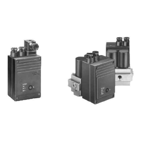
Tightness control TC
Technical Information · GB
3 Edition 07.14
• Test of two safety valves
• Short test period thanks to logical decision-making in the program sequence
• Adjustable test period which can be adapted to different systems
• Adjustable test instant allows quick system start
• Maximum safety thanks to self-monitoring electronics
• Less space required thanks to small dimensions
• EU certified
• UL listed, FM and AGA approved
แฟกซ์ : 02-888-3258
08-08-170-170
:
sales@add-furnace.com
AGA
Advertisement
Table of Contents

Related Manuals for krom schroeder TC


Summary of Contents for krom schroeder TC
-
Page 1: Tightness Control Tc
โทร: 02-888-3472 โทร: ออกแบบ แฟกซ์ : 02-888-3258 08-08-170-170 https://www.add-furnace.com E-mail: sales@add-furnace.com Tightness control TC Technical Information · GB 3 Edition 07.14 • Test of two safety valves • Short test period thanks to logical decision-making in the program sequence • Adjustable test period which can be adapted to different systems •... -
Page 2: Table Of Contents
3.5 Animation ..............29 Tightness control TC .......1 3.6 Test period t ...............30... -
Page 3: Application
TC 2 and TC 4 It is used in industrial thermoprocessing equipment, in boilers and Tightness controls TC 2 and TC 4 can be used with gas forced draught burners. solenoid valves of any nominal size, which are quick European standards EN 746-2 and EN 676 stipulate tightness opening or slow opening with start rate. - Page 4 Slow opening motorized valves VK up to DN 65 which are directly flanged together can also be checked by TC 2 TC 4 within a temperature range of 0 to 60° C (32 to 140° F). TC 4 Tightness control TC 4 consists of detection circuitry and can be installed in the control cabinet, separately from the system.
- Page 5 44 ซอยบรมราชชนนี 70 ถนนบรมรำชชนนี แขวงศำลำธรรมสพน์ เขตทวี ว ั ฒ นำ กรุ ง เทพฯ 10170 โทร: 02-888-3472 โทร: ออกแบบ แฟกซ์ : 02-888-3258 08-08-170-170 https://www.add-furnace.com E-mail: sales@add-furnace.com TC 2 in a gas inlet section between TC 1 mounted to a a quick open- combination control ing and a slow...
-
Page 6: Examples Of Application
V1: quick or slow opening valve with start rate. Supply signal forwarding Automatic burner control unit C = Gas solenoid valves PZ = Internal pressure sensor of the TC for the comparison of inlet pressure p and interspace pressure p L1(+ = Test volume N(-) 1 2 3... -
Page 7: Tc 116W With Combination Control Cg
แฟกซ์ : 02-888-3258 08-08-170-170 https://www.add-furnace.com E-mail: sales@add-furnace.com 1 .1 .2 TC 116W with combination control CG . .D or CG . .V Tightness control TC 1 is directly mounted to combination control CG..D or CG..V and checks gas solenoid valves TC 1 V1 and V2 in the combination control for tightness. -
Page 8: Tc 116W With Two-Stage Combination Control Cg
) PE burner control unit C = Gas solenoid valves 1 2 3 1 3 5 6 PZ = Internal pressure sensor of the TC for the comparison of inlet pressure p and interspace pressure p = Test volume 116W 1 2 3 CG..Z... -
Page 9: Tc 2 With Two Gas Solenoid Valves
โทร: 02-888-3472 โทร: ออกแบบ แฟกซ์ : 02-888-3258 08-08-170-170 https://www.add-furnace.com E-mail: sales@add-furnace.com 1 .1 .4 TC 2 with two gas solenoid valves Tightness control TC 2 checks gas solenoid valves V1 and V2 for tightness. If both valves are tight, the tightness control... -
Page 10: Tc 2 With Two Gas Solenoid Valves And One Auxiliary Valve For Discharge
แฟกซ์ : 02-888-3258 08-08-170-170 https://www.add-furnace.com E-mail: sales@add-furnace.com 1 .1 .5 TC 2 with two gas solenoid valves and one auxiliary valve for discharge Tightness control TC 2 checks the gas solenoid valves V1 TC 2 V2 and the auxiliary valve V3 for tightness. -
Page 11: Tc 2 With Two Gas Solenoid Valves And One Auxiliary Valve For Discharge
แฟกซ์ : 02-888-3258 08-08-170-170 https://www.add-furnace.com E-mail: sales@add-furnace.com 1 .1 .6 TC 2 with two gas solenoid valves and one auxiliary valve for discharge TC 2 Tightness control TC 2 checks the gas solenoid valves V1 V2 and the auxiliary valve V3 for tightness. -
Page 12: Tc 2 In A Multiple Burner System With 3 Valves Installed
โทร: 02-888-3472 โทร: ออกแบบ แฟกซ์ : 02-888-3258 08-08-170-170 https://www.add-furnace.com E-mail: sales@add-furnace.com 1 .1 .7 TC 2 in a multiple burner system with 3 valves TC 2 installed in series TC 2 When using slow opening main valves (V1 and V2), auxiliary... -
Page 13: Tc 3 With Two Gas Solenoid Valves
แฟกซ์ : 02-888-3258 08-08-170-170 https://www.add-furnace.com E-mail: sales@add-furnace.com 1 .1 .8 TC 3 with two gas solenoid valves Tightness control TC 3 checks the slow opening gas solenoid valves or motorized valves VK for tightness TC 3 using the auxiliary valves installed in TC 3. -
Page 14: Tc 3 With A Manually Resettable Valve
Once the tightness test has been carried out successfully, TC 3 forwards the OK enable signal. V1 and V2: any. A = Supply and signal forwarding PZ = Internal pressure sensor of the TC for the comparison of inlet pressure p and interspace pressure p = Outlet... -
Page 15: Tc 3 In A Multiple Burner System With 3 Valves Installed
แฟกซ์ : 02-888-3258 08-08-170-170 https://www.add-furnace.com E-mail: sales@add-furnace.com 1 .1 .10 TC 3 in a multiple burner system with 3 valves installed in series Tightness control TC 3 checks the slow opening main valves V1 and V2 for tightness. The test volume V TC 3 supplied and discharged via the TC 3 auxiliary valves. -
Page 16: Tc 4 With Two Gas Solenoid Valves
แฟกซ์ : 02-888-3258 08-08-170-170 https://www.add-furnace.com E-mail: sales@add-furnace.com 1 .1 .11 TC 4 with two gas solenoid valves Tightness control TC 4 checks gas solenoid valves V1 and for tightness. TC 4 The external pressure switch DG monitors the pressure be- tween the two valves. -
Page 17: Tc 4 With Two Gas Solenoid Valves And One Auxiliary Valve For Discharge
แฟกซ์ : 02-888-3258 08-08-170-170 https://www.add-furnace.com E-mail: sales@add-furnace.com 1 .1 .12 TC 4 with two gas solenoid valves and one auxiliary valve for discharge Tightness control TC 4 checks the gas solenoid valves V1 V2 and the auxiliary valve V3 for tightness. -
Page 18: Tc 4 In A Multiple Burner System With Two Auxiliary Valves For Supply And Discharge
แฟกซ์ : 02-888-3258 08-08-170-170 https://www.add-furnace.com E-mail: sales@add-furnace.com 1 .1 .13 TC 4 in a multiple burner system with two auxiliary valves for supply and discharge TC 4 Tightness control TC 4 checks the central shut-off valve V1, auxiliary valves V2 and V3 and several burner valves for tightness. -
Page 19: Tc 4 In A Multiple Burner System With 3 Valves Installed
แฟกซ์ : 02-888-3258 08-08-170-170 https://www.add-furnace.com E-mail: sales@add-furnace.com 1 .1 .14 TC 4 in a multiple burner system with 3 valves installed in series TC 4 Tightness control TC 4 checks the central shut-off valve V1 and the gas solenoid valve V2 for tightness. -
Page 20: Certification
Australian Gas Association, approval number: 4581 www.aga.asn.au/product_directory FM approved TC 1, TC 2 and TC 3 for 120 V and 230 V, TC 4 for 24 V, 120 V and 230 V Factory Mutual Research Class: 7411 Safety overpressure slam shut valves. -
Page 21: Function
11 and 12. 1 2 3 3 .1 .1 TC 116V for valVario controls VAS, VAG and VAD 1 2 3 4 5 6 7 8 9 10 11 12 The connection boxes of the valVario controls must be positioned on the same side and are connected via a single coupler plug, as shown. -
Page 22: Tc 2
44 ซอยบรมราชชนนี 70 ถนนบรมรำชชนนี แขวงศำลำธรรมสพน์ เขตทวี ว ั ฒ นำ กรุ ง เทพฯ 10170 โทร: 02-888-3472 โทร: ออกแบบ แฟกซ์ : 02-888-3258 08-08-170-170 https://www.add-furnace.com E-mail: sales@add-furnace.com 3 .1 .3 TC 2 L1(+) A = Supply and signal forwarding L1(+) L1(+) N(-) -
Page 23: Tc 4
โทร: 02-888-3472 โทร: ออกแบบ แฟกซ์ : 02-888-3258 08-08-170-170 https://www.add-furnace.com E-mail: sales@add-furnace.com 3 .1 .5 TC 4 Fault signalling contact on terminals 8 and 9: TEST OK signalling contact (not internally fused), max. 1 A for 264 V, max. 2 A for 120 V. -
Page 24: Program Sequence
TEST START vol- ume is discharged. V2 closes again. During the measurement time t , the TC checks the pressure p between the valves again. If the pressure p is now less than half the inlet pressure p /2, valve V1 is also OK. - Page 25 โทร: 02-888-3472 โทร: ออกแบบ แฟกซ์ : 02-888-3258 08-08-170-170 https://www.add-furnace.com E-mail: sales@add-furnace.com The tightness control TC runs program A or B depending on the initial situation . Both valves are checked for tightness respectively, but only one valve is opened at a time.
-
Page 26: Test Instant
1 L1 (+) 1 If the tightness control TC detects a leak on one of the TEST two valves, the red LED lights up for a fault on valve V1 or valve V2 . -
Page 27: Testing After Burner Run: Mode 2
If the tightness control TC detects a leak on one of the two valves, the red LED lights up for a fault on valve V1 V1 leaking or valve V2 . -
Page 28: แฟกซ์ : 02-888-3258
LEDs on the TC lights up to indicate a leak on valve V1 or valve V2. After a power failure, the external fault signal remains active. Both red LEDs are now lit. Once a tightness test has been carried out again, the TC detects the leaking valve. -
Page 29: Animation
(as on a DVD player). from the document library www.docuthek.com as an inde- To play the animation, you will need Adobe Reader 7 or a newer pendent application. version. If you do not have Adobe Reader on your system, TC · Edition 07.14... -
Page 30: Test Period T
3 .6 Test period t It is possible to check a specific leakage rate V using the The sensitivity of the tightness control TC can be adjusted TC. Within the scope of the European Union, the maximum by adapting the test period t for each individual system. - Page 31 VG 25 VG 40/VK 40 VG 50/VK 50 VG 65/VK 65 VG 80/VK 80 Test volume V for TC 410-10 is almost arbitrary thanks to VG 100/VK 100 the adjustable max. test period t of 600 s. VK 125 13.6 12.3...
-
Page 32: Test Volume V
[s] = 4 x 50 x 32.45 + 1 = 36.45 s Set the next highest value (40 s) with the jumper, see page 26 (Test instant). Selecting the relief valve, see page 34 (Project planning information). TC · Edition 07.14... -
Page 33: Selection
TC 318R05T * Designation “-1” only in type code for TC 4 ** An additional adapter plate is required for the TC 116V for attachment on the right- or left-hand side of valVario controls, see page 37 (Accessories) *** Max. test volume V TC 3, see page 34 (Project planning information) 4 .2 Type code... -
Page 34: Project Planning Information
3000 6 7 8 10 1000 2000 40 50 80 100 3000 1000 2000 4000 6000 10000 20000 40000 100000 (0.05 lbs/ft ① ② = = 2.01 kg/m (0.13 lbs/ft = 1.29 kg/m (0.08 lbs/ft ③= TC · Edition 07.14... -
Page 35: Start Rate
The tightness control TC must not be in contact with max. masonry, minimum distance 20 mm (0.78 inches). 5 .3 Installation Installation position TC 1 to TC 3: in the vertical or horizontal position, front panel must not point upwards or downwards. Installation position TC 4: any. -
Page 36: Tc 116V For Valvario Controls
แฟกซ์ : 02-888-3258 08-08-170-170 https://www.add-furnace.com E-mail: sales@add-furnace.com 5 .4 .1 TC 116V for valVario controls Snap attachment for DIN rails Width = 35 mm (1.36 inch). The connection boxes of the valVario controls must be posi- tioned on the same side and are connected via a coupler plug. -
Page 37: Accessories
44 ซอยบรมราชชนนี 70 ถนนบรมรำชชนนี แขวงศำลำธรรมสพน์ เขตทวี ว ั ฒ นำ กรุ ง เทพฯ 10170 โทร: 02-888-3472 โทร: ออกแบบ แฟกซ์ : 02-888-3258 08-08-170-170 https://www.add-furnace.com E-mail: sales@add-furnace.com Accessories 6 .1 Adapter plate for TC 116V, For VCS 6 – 9 attachment to valVario controls For VAS 1 – 3 61 (2.4") TC 116V (1.93") 44 (1.73") -
Page 38: External Pressure Switch For Tc 4
08-08-170-170 https://www.add-furnace.com E-mail: sales@add-furnace.com Accessories 6 .2 External pressure switch for TC 4 DG..C Gas pressure switches DG, DG..C for monitoring the pressure between the valves to be checked. For inlet pressures of 0.5 to 500 mbar (0.2 to 195 "WC). -
Page 39: Technical Data
: 10 to 60 s, adjustable. Mains voltage: Set at the factory to 10 s. 110/120 V AC, -15/+10%, 50/60 Hz, TC 3: power consumption of the installed valves during the 220/240 V AC, -15/+10%, 50/60 Hz, opening time t : max. 9.5 VA (W). -
Page 40: Indicators And Operating Controls
E-mail: sales@add-furnace.com 7 .1 Indicators and operating controls TEST = TEST phase (yellow) = Operating signal (green) = Fault valve 1 (red) = Fault valve 2 (red) = Reset button TC 1 – 3 TC 4 TC · Edition 07.14... -
Page 41: Dimensions
(2.56") (½ NPT) TC 1 TC 2 7 .2 Dimensions 7 .2 .1 TC 1, TC 2 = Supply and signal forwarding B = Automatic burner control unit C = Gas solenoid valves )= Inlet pressure p = Interspace pressure p... -
Page 42: Tc 3, Tc 4
(1.10") (2.56") (2.95") (2.05") (1.30") TC 4 TC 3 (2.24") 7 .2 .2 TC 3, TC 4 = Supply and signal forwarding ) = Inlet pressure p = Interspace pressure p ) = Outlet pressure p TC · Edition 07.14... -
Page 43: Converting Units
US unit × multiplier = SI unit 0.028 68.89 mbar "WC 2.54 mbar inch 25.4 0.45 3.79 litres ft/s 0.304 ° C = (° F - 32) × ° F = (° C × ) + 32 TC · Edition 07.14... -
Page 44: Maintenance Cycles
* The interspace pressure is the pressure between the gas solenoid valves to be checked for tightness. ** The test period t is the sum of the waiting time t , the fixed opening time t of 2 s and the measurement time t TC · Edition 07.14...
Need help?
Do you have a question about the TC and is the answer not in the manual?
Questions and answers