Advertisement
Quick Links
FEATURING:
● High MTF
● High Sensitivity
● High Contrast
● Short Cycle Time
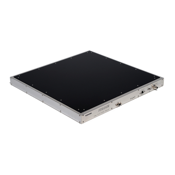
This product is FLAT PANEL IMAGER (hereafter called FPI) designed for medical radiographic
diagnosis. Featuring excellent image quality by implementing in-house produced Cesium Iodide (CsI)
for X-ray scintillator. It has large effective size area of 43×43cm, which is suitable for radiographic
procedures such as chest screenings etc.
– High Resolution and High DQE CsI Phosphor Screen –
• TETD has long experience to develop and manufacture fine and thick pillar structure of CsI
phosphor screen with high resolution and high sensitivity.
– Low Noise ROIC and Analog Circuit –
• ROIC and analog circuit are designed and specified to be suitable for high sensitivity X-ray
conversion layer.
★ The information contained herein is presented only as a guide for the applications of our products.
No responsibility is assumed by TOSHIBA ELECTRON TUBES & DEVICES CO., LTD. (TETD) for any infringements of patents or other rights of the
third parties which may result from its use. No license is granted by implication or otherwise under any patent or patent rights of TETD or others.
★ The information contained herein may be changed without prior notice. It is therefore advisable to contact TETD before proceeding with the design of
equipment incorporating this product.
Technical Data
X-Ray FLAT PANEL IMAGER
FDX4343R
Sup. Symbol /B
Active Area: 430(H)×439(V)mm
(16.9" ×17.3" )
No.TE-FDX4343R/B 2011-11-01
TD
Advertisement

Related Manuals for Toshiba FDX4343R

Summary of Contents for Toshiba FDX4343R
- Page 1 ★ The information contained herein is presented only as a guide for the applications of our products. No responsibility is assumed by TOSHIBA ELECTRON TUBES & DEVICES CO., LTD. (TETD) for any infringements of patents or other rights of the third parties which may result from its use.
- Page 2 FDX4343R COMPONENTS AND CHARACTERISTICS Flat Panel Sensor Unit: Sensor Protection Plate ..................Carbon Fiber Plate Cooling ........................ Natural Air Cooling Input..................DC24V (from AC/DC Power Supply) Power Consumption ....................Maximum 20W Overall Dimensions..............512×495×43mm (W(H)×D(V)×(H)) Weight ......................... 9 kg (approx.) Power Supply Unit: Input......................
- Page 3 FDX4343R ACCESSORIES Cables: AC Cable ..........................1.8m×1 GND Cable ..........................3m×2 OPTION ACCESSORIES DC Cable (Sensor Unit - Power Supply Unit) Name Length 1 ECB-F002A/G 2 ECB-F002A-10/G 3 ECB-F002A-20/G * Please contact to our local sales for further information.
- Page 4 FDX4343R MAIN CHARACTERISTICS Image Format: X-ray Conversion Layer ....Cesium Iodide (Csl) with Amorphous Silicon (a-Si) Photodiode Active Area ................430(H)×439(V)mm (16.9×17.3 inch) Pixel Matrix ......................3008(H)×3072(V) Pixel Pitch..........................143 μ m Cycle Time......................Shot to Shot 6sec. Performance: Limiting Resolution ....................3.7 Lp/mm typ.
- Page 5 FDX4343R Product Components and Interface: Sensor Unit Power DC24V Supply Unit Control Board Image Data &Control PC (User) Ethernet X-ray Sync X-ray Control Unit (User) Gate Driver ROIC Unit TFT Panel NOTE: Do not disconnect Ethernet connection while DC24V is operating and supplying to Sensor Unit.
- Page 6 FDX4343R Image Acquisition Communication Block Diagram: Ethernet Connector Ethernet Command module Signal IO module D-Sub D-SUB Connector Connector X-ray Controller X-ray Controller Communication Availability: Ethernet Command Control D-Sub Signal Control Signal Name Type (PC) (X-ray Controller) EXP_REQ INPUT EXP_OK OUTPUT *EXP_REQ Command Response...
- Page 7 FDX4343R Image Acquisition Control Interface: D-Sub Signal Control Interface Operation Sequence Description of the sequence 1. By receiving “EXP_REQ” during “Refresh” status proceeds to “Exposure” after completion of “Refresh”. 2. Continues “EXP_OK” signal ON during “Exposure”. ON period is defined by Image Acquisition mode table.
- Page 8 FDX4343R (2) Double Exposure FPI Drive Exposure Read Exposure Read ③ ② ① EXP_REQ <IN> EXP_OK <OUT> EXPOSURE DATA_STORAGE 1st image deta 2nd Image data POWER ON A: EXP_REQ width Minimum 1ms. B: Refresh period For line drive (3072 Line scan) 36.9ms.
- Page 9 FDX4343R Image Acquisition Control Interface: Ethernet Interface Command Control Operation Sequence Description of the sequence 1. By receiving “EXP_REQ” request command during “Refresh” status proceeds to “Exposure” after completion of “Refresh”. 2. Continues “EXP_OK” signal ON during “Exposure”. ON period is defined by Image Acquisition mode table.
- Page 10 FDX4343R (2) Double Exposure FPI Drive Exposure Read Exposure Read ③ ② ① EXP_REQ <IN> EXP_OK <OUT> EXPOSURE DATA_STORAGE 1st image deta 2nd Image data POWER ON ①:EXP_REQ-EXP_OK period ................Maximum 40ms ②:EXP_REQ-DATA STORAGE period ..... Maximum 2000ms (case EXPOSURE 500ms) ③:POWER ON-EXP_REQ period ..............
- Page 11 FDX4343R Image Acquisition Control Interface: 1. Pins assign Pin No Signal name Contents TEST+ Don’t connect. This pin is used for TEST. Image acquisition (X-ray exposure) EXP_REQ+ Input Request signal + Image acquisition (X-ray exposure) EXP_OK+ Output Period signal +...
- Page 12 FDX4343R 4.Output Circuit 4.1 5V CMOS Level Type FPI side User system side Pin3 Pin8 D-Sub 9pin 4.2 Open Collector Type User system side FPI side 22Ω Pin4 Max Voltage 28V protective resistance Pin9 D-Sub 9pin Protective resistance more than 1.4kΩ must be inserted in series.
- Page 13 FDX4343R The information about EMC conformity (IEC60601-1-2 Ed2, 2001+AMD.1, 2004) Guidance and manufacturer’s declaration - electromagnetic emissions The X-Ray FLAT PANEL IMAGER (hereafter called FPI) is intended for use in the electromagnetic specified below. The customer or the user of the FPI should assure that it is used in such an environment.
- Page 14 FDX4343R Guidance and manufacturer’s declaration – electromagnetic immunity The FPI is intended for use in the electromagnetic specified below. The customer or the user of the FPI should assure that it is used in such an environment. IEC60601 Electromagnetic environment -...
- Page 15 FDX4343R Guidance and manufacturer’s declaration – electromagnetic immunity The FPI is intended for use in the electromagnetic environment specified below. The customer or the user of the FPI should assure that it is used such an environment. IEC 60601 Compliance Electromagnetic environment –...
- Page 16 FDX4343R Recommended separation distances between portable and mobile RF communications equipment and the FPI. The FPI is intended for use in an electromagnetic environment in which radiated RF disturbances are controlled. The customer or the user of the FPI can help prevent electromagnetic interference...
- Page 17 FDX4343R INSTALLATION For installing the FPI in the apparatus, refer to the dimensional outlines. INSTALLING HOUSING IN APPARATUS: 1. Use the screw holes 10-M4 (Depth 8). 2. The screws should be fixed all screw holes of each part. Also, the screw thread length entering the screw holes should be each depth of holes.
- Page 18 FDX4343R MAINTENANCE AND CHECK DAILY CHECK ITEMS Before using the sensor unit, check the following items: (1) Environment - The environmental conditions for operation must be adequate. (2) Appearance - Wiring and appearance must be free from any abnormality. (3) Operation - The sensor unit must operate normally after power on.
- Page 19 FDX4343R SAFETY PRECAUTIONS AND WARNING Find this document before using X-Ray FLAT PANEL IMAGER (FPI) This document describes the attention of equipment manufactures and users to use safety X-Ray FLAT PANEL IMAGER (hereafter called FPI). Please find the technical data sheet of each product and this document “SAFETY PRECAUTIONS AND WARNING”...
- Page 20 FDX4343R 7. Installing to the Equipment Installing FPI housing to the equipment by according to the technical data sheet or the specification. It will prevent dropping off of FPI from the equipment. 8. Shipping and Handling The weight of FPI is mentioned at technical data sheet or the specification. Please take into account on this weight for preventing any dangers during usage.
- Page 21 FDX4343R 15. Mechanical Shock and Vibration Do not give a mechanical shock or vibration to the FPI housing. It may cause the malfunction of FPI due to break down of TFT panel. Do not use FPI in car, bus and/or truck. FPI is not designed to be used in such applications.
- Page 22 FDX4343R 25. Temperature Sensor The FPI is equipped with temperature sensor. Alarm appears when it detects abnormal internal temperature. Stop operating FPI when it appears then check surrounding temperature. 26. Cables Users must use cables attached with the FPI. Be sure to connect correctly and do not loosen cables.
- Page 23 FDX4343R CAUTION LABEL This label is a caution label to notify the user of the following point. "This contents are quite important for safety" Attachment position: Housing -23-...
- Page 24 FDX4343R DEFINITION SYMBOL MARKS (1) CE MARKING OF CONFORMITY (2) SERIAL NUMBER (3) MANUFACTURER (4) DATE OF MANUFACTURE (5) AUTHORISED REPRESENTATIVE IN THE EUROPEAN COMMUNITY (6) PROTECTIVE EARTH (7) ATTENTION, CONSULT ACCOMPANYING DOCUMENTS -24-...
- Page 25 FDX4343R DIMENSIONAL OUTLINE (Flat Panel Sensor Unit) Unit: mm 501±1 495±1 43±1 IP Address Select Power Connector Frame Ground 1;Include a Screw Head LAN Connector D-Sub Connector Display for Mode 2;Include a Power Connector Wired Image -25-...
- Page 26 FDX4343R DIMENSIONAL OUTLINE (Flat Panel Sensor Unit) Unit: mm ±0.5 ±0.5 30.5 124.5 93.5 ±0.5 93.5 124.5 ±0.5 30.5±0.5 30.5 ±0.5 (30.5) 10-M4 Depth:8mm -26-...
- Page 27 FDX4343R DIMENSIONAL OUTLINE (Power Supply Unit) Unit: mm ±1 ±1 -27-...
- Page 28 1385 SHIMOISHIGAMI, OTAWARA-SHI, TOCHIGI-KEN, 324-8550, JAPAN PHONE: +81-287-26-6666 FAX: +81-287-26-6060 http://www.toshiba-tetd.co.jp/ ● Toshiba Electron Tubes & Devices Co., Ltd. meets the Environmental Management System Standard, ISO14001 ● Toshiba Electron Tubes & Devices Co., Ltd. meets internationally recognized Standards for Quality Management System ISO9001, ISO13485.