Advertisement
Table of Contents
- 1 Table of Contents
- 2 Safety Precautions
- 3 Important Safety Instructions
- 4 Operation of Current Device (Optional)
- 5 Air Conditioner Features
- 6 Control Panel Operation
- 7 Dip Switches Configurations (Optional)
- 8 Dip Switches Configurations by Panel
- 9 Wall Thermostat Terminal
- 10 Installation
- 11 Care and Cleaning
- 12 Troubleshooting
- Download this manual
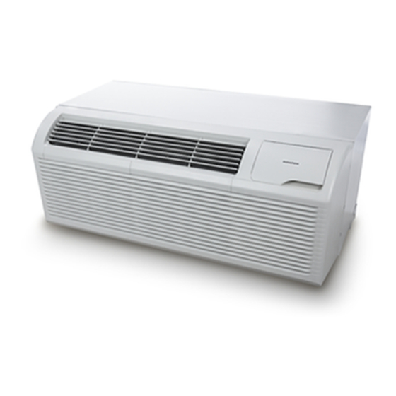
AIR CONDITIONER / HEAT PUMP
INSTALLATION INSTRUCTIONS
Model:
DCP073A25AA
DCP073A35AA
DCP093A25AA
DCP093A35AA
ATTENTION INSTALLING PERSONNEL
As a professional installer you have an obligation to know
the product better than the customer. This includes all safe-
ty precautions and related items.
Prior to actual installation, thoroughly familiarize yourself
with this Instruction Manual. Pay special attention to all
safety warnings.
Often during installation or repair it is possible to place
yourself in a position which is more hazardous than when
the unit is in operation.
This manual must be left with the owner of the
IO-930
05/2022
PACKAGED TERMINAL
DCP123A35AA
DCP123A50AA
DCP153A35AA
DCP153A50AA
equipment.
19001 Kermier Rd., Waller, TX 77424
© 2022 Goodman Manufacturing Company, L.P.
is a registered trademark of Maytag Corporation or its related companies and is used under
license to Goodman Company, L.P., Houston, TX, USA. All rights reserved.
DHP093A25AA
DHP093A35AA
DHP094A35AA
DHP123A35AA
Before using your air conditioner, please read this man-
ual carefully and keep it for future reference.
Only personnel that have been trained to install, adjust,
service or repair(hereinafter, "service") the equipment spec
ified in this manual should service the equipment. The manu
facturer will not be responsible for any injury or property
damage arising from improper service or service proce
dures. If you service this unit, you assume responsibility for
any injury or property damage which may result. In addition,
in jurisdictions that require one or more licenses to service
the equipment specified in this manual, only licensed per
sonnel should service the equipment. Improper installation,
adjustment, servicing or repair of the equipment specified
in this manual, or attempting to install, adjust, service or
repair the equipment specified in this manual without proper
training may result in product damage, property damage,
personal injury or death.
www.amana-ptac.com
DHP123A50AA
DHP124A35AA
DHP153A35AA
DHP153A50AA
WARNING
-
-
-
-
Advertisement
Table of Contents

Related Manuals for Amana distinctions DCP073A25AA


Summary of Contents for Amana distinctions DCP073A25AA
- Page 1 19001 Kermier Rd., Waller, TX 77424 www.amana-ptac.com © 2022 Goodman Manufacturing Company, L.P. IO-930 is a registered trademark of Maytag Corporation or its related companies and is used under 05/2022 license to Goodman Company, L.P., Houston, TX, USA.
-
Page 2: Table Of Contents
TABLE OF CONTENTS The precautions listed in this Installation Manual are intended as supplemental to existing practices. However, if there is a direct conflict between existing practices and SAFETY PRECAUTIONS............3 the content of this manual, the precautions listed here take IMPORTANT SAFETY INSTRUCTIONS......5 precedence. -
Page 3: Safety Precautions
SAFETY PRECAUTIONS CAUTION To prevent injury to the user or other people and property Do not operate your air conditioner in a wet room such as a damage, the following instructions must be followed. Incor- bathroom or laundry room. rect operation due to ignoring instructions may cause harm or damage. - Page 4 WARNING WARNING Always ensure effective earthing. Incorrect earthing may Do not disassemble or modify unit. It may cause failure and cause electric shock. electric shock. CAUTION WARNING When the air filter is to be removed, do not touch the metal Do not allow water to run in electric parts.
-
Page 5: Important Safety Instructions
CAUTION Always insert the filters securely. Clean filter once every two weeks. Operation without filters may cause failure. CAUTION Do not use strong detergent such as wax or thinner but use a soft cloth. Appearance may be deteriorated due to change of product color or scratching of its surface. -
Page 6: Air Conditioner Features
Memory The unit has memory. If power is lost, all of the control settings (mode, fan speed, on / off and configuration) are remembered. When power is restored, the unit will start back up in the mode (and configuration) it was in when power was lost. - Page 7 CONTROL PANEL OPERATION 2. There is a 3-minute minimum compressor run time at any setting to prevent short cycling. The indoor fan motors starts before the compressor and stops after The control panel keypad will look like the following Figure 1. the compressor cycles off.
-
Page 8: Dip Switches Configurations (Optional)
Control Code (on some models): Accessory LC - Pads on the control panel is not available. The unit can be set by using wire controller only. FC - Pads on the control panel and wire controller are not available. The unit can be set by using FRONT DESK CONTROL only. - Page 9 Figure 3 Figure 4 UP (ON) Down (OFF) Remarks For Heat Pump unit only Electric Heat Only Electric Heat and Pump Heat Temperature Display in °F Temperature Display in °C Wall Thermostat Enable Control Panel Enable UP*UP: 61°F - 86°F (16°C - 30°C); Two Configurations UP*DOWN: 65°F - 78°F (17°C - 26°C);...
-
Page 10: Dip Switches Configurations By Panel
Set Point Temperature Limits Provides a restricted range of temperature control. DIP SWITCHES CONFIGURATIONS BY PANEL CONTROL (OPTIONAL) DIP switches configurations by Panel Control (Optional) • Turn off the unit. • Press the up (+) and down (-) buttons together for 3 seconds to activate the dip switches configurations by panel control (see Figure 5). -
Page 11: Wall Thermostat Terminal
WALL THERMOSTAT TERMINAL (OPTIONAL) IMPORTANT: Only trained, qualified personnel should access electrical panel on unit and install electrical accessories. Please contact your local electrical contractor, dealer, or distributor for assistance. Thermostat Wire Routing Thermostat wire is field supplied. Recommended wire gauge is 18 to 20 gauge solid thermostat wire. -
Page 12: Installation
INSTALLATION How to Install the Unit: CAUTION There are sharp edges that can cause serious cuts. When lifting the air conditioner, it is HEAVY. Use two people to lift. CAUTION • For existing sleeve, you should measure the wall sleeve dimensions. UNIT DAMAGE HAZARD •... - Page 13 Rotate the vent control lever to either open or close the vent door. (See Figure 10) Figure 10 NOTE: When vent control lever set at CLOSE, only the air inside the room is circulated and filtered. When set at OPEN, some outdoor air will be drawn into room.
-
Page 14: Care And Cleaning
CAUTION Always insert the filter securely, clean filter once every two weeks as required. CARE AND CLEANING Front Panel and Case Figure 14 Turn unit off and disconnect power supply. To clean, use water and a mild detergent. DO NOT use bleach and abra- sivers. -
Page 15: Troubleshooting
TROUBLESHOOTING SOLUTIONS POSSIBLE CAUSES UNIT DOES NOT START · Check that plug is plugged securely in wall receptacle. NOTE: Plug has a test / reset button on it. Make sure that the plug has not · Unit may have become unplugged tripped. - Page 16 TROUBLESHOOTING POSSIBLE CAUSES SOLUTIONS · When outdoor temperature is approximately 55°F or below, frost may form on ICE OR FROST FORMS ON INDOOR COIL the indoor coil when unit is in Cooling Mode. Switch unit to FAN operation until ice or frost melts.
Need help?
Do you have a question about the distinctions DCP073A25AA and is the answer not in the manual?
Questions and answers