Table of Contents
Advertisement
Quick Links
Advertisement
Table of Contents

Related Manuals for Durr Dental VistaScan Mini Easy 2.0


Summary of Contents for Durr Dental VistaScan Mini Easy 2.0
- Page 1 VistaScan Mini Easy 2.0 XPS07.1D... Installation and operating instructions...
- Page 2 https://qr.duerrdental.com/2144100118...
-
Page 3: Table Of Contents
Contents Contents Operation ..... . . Image plate scanner ..Image plate ....Important information Light protection cover . - Page 4 Contents 11.2 Light protection cover ..11.3 Image plate ....11.4 Protective cover ... . . 11.5 Image plate storage box .
-
Page 5: Important Information
All other Model number languages are translation of the original manual. These operating instructions apply to: CE labelling VistaScan Mini Easy 2.0, order number: 2144100500 (XPS07.1D1) Conformity mark for the United Kingdom Warnings and symbols of Great Britain and Northern Ireland... -
Page 6: Copyright Information
Intended purpose xx % Lower and upper humidity limits xx % VistaScan Mini Easy 2.0 The unit is intended exclusively for use in dental Lower and upper temperature limits applications for the scanning and processing of image data on an image plate. -
Page 7: Improper Use
Improper use Installation and repairs Installation, readjustments, alterations, ❯ VistaScan Mini Easy 2.0 upgrades and repairs must be carried out by Any other usage or usage beyond this scope is Dürr Dental or by qualified personnel specifi- deemed to be improper. The manufacturer cally approved and authorized by Dürr Dental. -
Page 8: Essential Performance Charac
Do not expose the unit to any strong vibrations ❯ Essential performance char- or shocks. acteristics The VistaScan Mini Easy 2.0 unit does not have 2.11 Disposal any essential performance characteristics as set An overview of the waste keys for Dürr out in IEC 60601--1 (EN 60601--1) section 4.3. -
Page 9: Protection From Threats From The
Important information Image plate The image plate contains barium compounds. Dispose of the image plate properly in accord- ❯ ance with the locally applicable regulations. In Europe, dispose of the image plate in ❯ accordance with waste code 20 03 01 "Mixed municipal waste". -
Page 10: Product Description
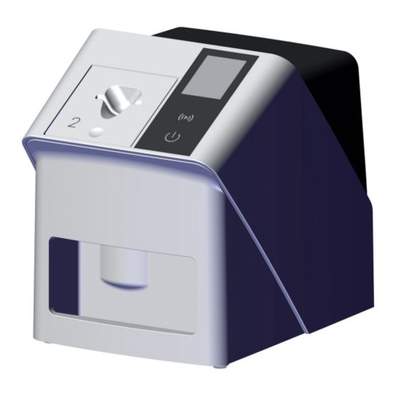
Product description Product description Overview b a c k VistaScan Mini Easy 2.0 image plate scanner Plate guides (S0 and S2) VistaScan IQ image plate VistaScan Light protection cover Plus Network cable (3 m) Image plate storage box Power supply unit with country-specific adapter... -
Page 11: Scope Of Delivery
... 2144110001 conversion set for endo-exposures . . 2130100014 – VistaScan Mini Easy 2.0 basic unit Bite protector S4 (100 each) ..2130-074-03 –... -
Page 12: Wear Parts And Replacement
Product description Light protection cover Plus S3 2.7 x 5.4 cm (100 each) ..2130-083-00 Light protection cover Plus S4 5.7 x 7.6 cm (100 each) ..2130-084-00 Light protection cover Plus S0, white 2 x 3 cm (100 each) . -
Page 13: Technical Data
Product description Technical data Image plate scanner (XPS07.1D...) Electrical data for the device Voltage V DC Max. current consumption 1.25 Output < 30 Type of protection IP20 Electrical data – power supply unit Nominal input voltage V AC 100 - 240 Frequency 50/60 Nominal output voltage... - Page 14 Product description Ambient conditions during storage and transport Temperature °C -20 to 60 °F -4 to +140 Relative humidity 10 - 95 Air pressure 750 - 1060 Classification Medical Device Class (MDR) Laser class (unit) In accordance with IEC 60825-1:2014 Laser source Laser class In accordance with IEC 60825-1:2014...
- Page 15 Product description Electromagnetic compatibility (EMC) Interference immunity measurements cover Immunity to interference, near fields of wireless HF com- munication devices IEC 61000-4-3:2006+A1:2007+A2:2010 Compliant See immunity to interference table, near fields of wireless HF communication devices Immunity to interference table, near fields of wireless HF communication devices Radio service Frequency band Test level...
- Page 16 Product description Electromagnetic compatibility (EMC) Interference immunity measurements supply input Immunity to interference, line-conducted disturbances induced by high-frequency fields – AC voltage grid IEC 61000-4-6:2013 0.15 - 80 MHz Compliant ISM frequency bands 0.15 - 80 MHz 80 % AM at 1 kHz Immunity to interference due to voltage dips, short inter- ruptions and voltage variations Compliant...
- Page 17 Product description Ambient conditions during storage and transport Temperature °C < 45 °F < 113 Relative humidity < 80 Dimensions of intraoral image plates 22 x 35 0.87 x 1.38 24 x 40 0.94 x 1.57 31 x 41 1.22 x 1.61 27 x 54 1.06 x 2.13 57 x 76...
-
Page 18: Image Plate Scanner (Xps07.1D
Product description Operation Type plate The type plate is located on the rear of the Image plate scanner device. Plate guides: User interface and display Collection tray The image plate scanner is used to read image REF Order number data stored on an image plate and to transfer the Serial number data to the imaging software (e.g. -
Page 19: Image Plate
Product description Operating elements Connections The connections are located on the rear of the unit, underneath the cover. On / off switch USB port (additional accessory) Confirm button Network connection Display Reset button Connection for power supply unit On / off switch The on / off switch shows different states of the Image plate unit:... -
Page 20: Light Protection Cover
Product description Intraoral Image plate storage box Inactive side Active side Image plates packed in light protection covers back can be stored in the image plate storage box until the next use. The image plate storage box protects the image plate and the light protection cover against contamination and dirt. -
Page 21: Assembly
Assembly Installation Assembly Setting up the unit Only qualified specialists or employees NOTICE trained by Dürr Dental are permitted to Risk of damage to sensitive compo- install, connect and start using the unit. nents in the unit as a result of shocks or vibrations Requirements Do not expose the unit to any strong... -
Page 22: Electrical Connections
Assembly Electrical connections Remove the cover from the back of the unit ❯ using a suitable tool (e.g. slotted-head screw- Safety when making electrical connections driver). The device must only be connected to a cor- ❯ rectly installed power outlet. Do not place non-fixed multi-socket units on ❯... -
Page 23: Connecting The Device To The Network
Assembly Refit the cover. Combining devices safely ❯ – The overall safety of the unit and its main per- formance features are independent of the net- work. The device is designed for operation independent of a network. However, some of the functions are not available in this case. - Page 24 Assembly Connecting the unit via the network cable Refit the cover. ❯ Remove the cover from the back of the unit ❯ using a suitable tool (e.g. slotted-head screw- driver). When operating the device, the rear side cover must be mounted. Connect the supplied network cable to the net- ❯...
-
Page 25: Commissioning
Assembly Commissioning Configuring the unit The VistaScan service tool is used to configure NOTICE the unit. Start the Service-Tool in VistaSoft: ❯ Short circuit due to the build up of Select > Units > Configure > Maintenance condensation > Service Tool. Do not switch on the unit until it has ❯... - Page 26 Assembly Select the image type (e. g. Intraoral). ❯ Scan an image plate, see "10 Operation". ❯ 2144100118L02 2208V002...
-
Page 27: X-Ray Unit Settings
Assembly X-ray unit settings If 60 kV can be set on the X-ray unit, this setting is preferred. The standard exposure values for F-speed film (e. g. Kodak Insight) can be used. The following table shows the standard values for the exposure time and the dose area product of an image plate for an adult patient. - Page 28 Assembly Document the results. ❯ Carry out and document the instruction and handover for the unit. ❯ A sample handover report is included in the attachment. 2144100118L02 2208V002...
-
Page 29: Usage
Usage Usage CAUTION Image plates are toxic Image plates that are not packed in a Correct use of image light protection cover can lead to poi- plates soning when placed in the mouth or swallowed. WARNING Only place image plates in the ❯... -
Page 30: 10 Operation
Usage 10 Operation Protect the image plates against sunlight and ❯ ultraviolet light. Store image plates in a light protection cover or CAUTION intraoral/extraoral foil cassette of the correct The image data on the image plate is size. not permanent. Image plates will be pre-exposed on exposure ❯... -
Page 31: Switch On The Unit
Usage 10.1 Switch on the unit. The plate guide can be changed at any time. To avoid loss of image quality, do Switch on the unit by tapping the on / off ❯ not change the plate guide during a scan. switch The on / off switch lights up briefly and the unit Press your finger into the recess and at the... -
Page 32: X-Ray
Usage 10.3 X-ray Completely slide the image plate into the light ❯ protection cover. The white (inactive) side of the The procedure is described using an IQ image plate must be visible. S2 image plate as an example. Use only IQ image plates with the unit. The unit is unable to read any other types of image plates. - Page 33 Usage Taking the X-ray image WARNING NOTICE Contamination of the unit Damage to the image plate caused by Clean and disinfect the light protection ❯ cover before removing the image plate. a sharp-edged holding system Only use holding systems that will not ❯...
-
Page 34: Scanning The Image Data Via A Computer
Usage 10.4 Scanning the image data via Set acquisition mode. ❯ Recording starts directly. a computer The unit will display an animated visual symbol requesting insertion of the image plate. Starting the image plate scanner and soft- ware Only insert the image plate when the bar above the animated sequence has The reading-out process is described turned to green. -
Page 35: Erasing The Image Plate
Usage Slide the image plate out of its light protection 10.5 Erasing the image plate ❯ cover downwards into the device until the The image data is automatically erased after image plate is automatically drawn in. scanning. The special ERASE mode only activates the era- sure unit of the image plate scanner. -
Page 36: 11 Cleaning And Disinfection
Usage 11 Cleaning and disinfection Pull the protective cover over the device so ❯ that it is completely covered. Make sure that When cleaning and disinfecting the unit and its the markings are at the front. accessories, observe country-specific directives, standards and specifications for medical prod- ucts as well as the specific specifications for den- tal practices and clinics. -
Page 37: Light Protection Cover
Usage Disinfect the surfaces using a disinfection wipe. 11.3 Image plate ❯ Alternatively, use disinfectant on a soft, lint-free Cleaning and disinfection wipes are unsuitable for cloth. cleaning image plates and may cause damage to them. Plate guides: Only use a cleaning agent that is compatible with The plate guide must be cleaned and disinfected the materials: if there are indications of contamination or visible... - Page 38 Usage tray in the event of contamination or visible soil- ing. Dürr Dental recommends the following disinfec- tants for the image plate storage box: FD 366 sensitive Dürr Dental recommends the following disinfec- tants for the image plate storage tray: FD 350 and FD 366 sensitive Clean the surface of the image plate storage ❯...
-
Page 39: 12 Maintenance
Usage 12 Maintenance 12.1 Recommended maintenance schedule Only trained specialists or personnel trained by Dürr Dental may service the device. Prior to working on the unit or in case of danger, disconnect it from the mains. The recommended maintenance intervals are based on using the device for 15 intraoral images per day and 220 working days per year. -
Page 40: Troubleshooting
Troubleshooting Troubleshooting 13 Tips for operators and service technicians Any repairs exceeding routine maintenance may only be carried out by qualified personnel or our service. Prior to working on the unit or in case of danger, disconnect it from the mains. 13.1 Poor X-ray image Error... - Page 41 Troubleshooting Error Possible cause Remedy X-ray image only shadowy The X-ray dose on the image Increase X-ray dose. ❯ plate was insufficient Amplification (HV value) is set Increase amplification (HV ❯ too low in the software value). Unsuitable scanning mode Select a suitable scanning ❯...
- Page 42 Troubleshooting Error Possible cause Remedy X-ray image cut off, part miss- The metal part of the X-ray tube When taking an X-ray, make ❯ is in front of the X-ray beam sure there are no metal parts between the X-ray tube and the patient.
- Page 43 Troubleshooting Error Possible cause Remedy X-ray image is stretched Incorrect light protection cover Only use original accessories. ❯ or image plate used lengthwise with bright, hori- zontal stripes Dirt in the laser slit (e.g. hair, Clean the laser slit. X-ray image split vertically ❯...
-
Page 44: Software Error
Troubleshooting Error Possible cause Remedy The X-ray image shows a pre- After the barrier envelope has Do not push out the image ❯ been torn off and before pushing plate until the torn-off light erasure at one end the PSP into the input unit, the protection cover has been phosphor storage plate is placed on the input unit. -
Page 45: Fault On The Unit
Troubleshooting Error Possible cause Remedy Error during data transmission Connecting cable used is incor- Only use original cables. ❯ rect or too long between unit and computer. Error message "CRC error timeout" Software message: "VistaSoft The image plate was exposed When diagnosing the X-ray ❯... - Page 46 Troubleshooting Error Possible cause Remedy Unit is on, but there is no dis- Touch screen initialisation fault Switch the unit off and back ❯ on again. play on the touch screen Touch screen brightness set too Update the firmware. ❯ dark Increase the brightness of the ❯...
-
Page 47: Error Message On Display
Troubleshooting 13.4 Error message on display Error Possible cause Remedy Error code -1008 Internal connection interrupted Update the firmware. ❯ Temperature of unit too high Allow the unit to cool down. Error code 1010 ❯ Inform a Service Technician. ❯ Error code 1022 Subassembly not initialised Fault in software, update the... - Page 48 Troubleshooting Error Possible cause Remedy Error code 1160 Final radiation deflector rotation Inform a Service Technician. ❯ speed not attained Update the firmware. ❯ Replace the radiation deflec- ❯ tor subassembly if the prob- lem occurs regularly. Error code -1171 Fault on laser Send the unit for repair.
-
Page 49: Appendix
Appendix Appendix 14 Scanning times The scanning time corresponds to the time taken for complete scanning of image data and depends on image plate format and pixel size. The time to image will depend largely on the computer system used and its work load. Times stated are approximate. -
Page 50: File Sizes (Uncompressed)
Appendix 15 File sizes (uncompressed) The actual file size will depend on the image plate format and the pixel size. File sizes stated are approx- imate and have been rounded upwards. Suitable compression methods can considerably reduce the file size without loss of data. Theoretical resolution (LP/mm) Pixel size (μm) -
Page 51: 16 Handover Record
Appendix 16 Handover record This document confirms that a qualified handover of the medical device has taken place and that appropriate instructions have been provided for it. This must be carried out by a qualified adviser for the medical device, who will instruct you in the proper handling and operation of the medical device. Product name Order number (REF) Serial number (SN) -
Page 52: 17 Country Representatives
Appendix 17 Country representatives Country Address UK Responsible Person: Duerr Dental (Products) UK Ltd. 14 Linnell Way Telford Way Industrial Estate Kettering, Northants NN 16 8PS Уповноважений представник в Україні: Приватне підприємство “Галіт” вул. 15 квітня, 6Є, с. Байківці, Тернопільський р-н, 47711, Україна... - Page 56 Hersteller / Manufacturer: DÜRR DENTAL SE Höpfigheimer Str. 17 74321 Bietigheim-Bissingen Germany Fon: +49 7142 705-0 www.duerrdental.com info@duerrdental.com...
Need help?
Do you have a question about the VistaScan Mini Easy 2.0 and is the answer not in the manual?
Questions and answers