Table of Contents
Advertisement
Quick Links
Advertisement
Table of Contents

Related Manuals for GeoSmart NETZERO BW Series


Summary of Contents for GeoSmart NETZERO BW Series
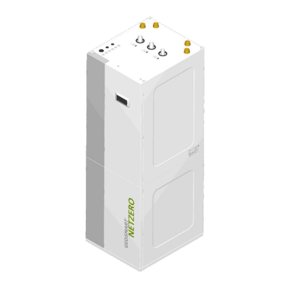
- Page 1 NETZERO BW NETZERO CW TECHNICAL SERVICE MANUAL MODEL: SERVICE CONTACT:...
-
Page 3: Table Of Contents
Contents Controller user guide ................................4 1.1. Control panel ..................................4 1.2. Main screen ................................... 5 1.3. Active components ................................5 1.4. Mode ...................................... 6 1.5. Operation program ................................7 1.6. Heat pump status ................................... 8 1.7. List of user menus ................................10 1.8. -
Page 4: Controller User Guide
This allows the user to access the selected menu. This is used to move from one adjustable parameter to another in the same screen. This is used to access the INFORMATION menu directly from the main screen. GEOSMART ENERGY... -
Page 5: Main Screen
Aerothermal fan activated Source pump activated Compressor in start-up phase Compressor activated Compressor in shut-down phase Production pump activated Heating units activated Cooling units activated Auxiliary heating unit activated HTR system activated Crankcase heating activated. GEOSMART ENERGY... -
Page 6: Mode
Note: After all the stages set in the floor drying program are completed, the heat pump returns to normal operation and this screen disappears. If there are requests for the enabled services, the heat pump deals with them. GEOSMART ENERGY... -
Page 7: Operation Program
The heat pump automatically switches between the WINTER/SUMMER operating programs, depending on the outside temperature. The temperatures and time required for the switch must be adjusted by the user. REMOTE Control WINTER / SUMMER program selection is triggered by an external signal. GEOSMART ENERGY... -
Page 8: Heat Pump Status
The heat pump is off due to an active time schedule or calendar and is therefore not available to activate any of its functions. OFF status due to data bus signal The heat pump is off due to an external signal through the data bus and is therefore not available to activate any of its functions. GEOSMART ENERGY... - Page 9 The EVU signal is used in some countries by the electricity company to control electrical consumption. The EVU signal prevents energy production by the compressor and the auxiliary equipment. Circulator NOTE pumps, valves and other components can be activated to consume energy from the storage systems. GEOSMART ENERGY...
-
Page 10: List Of User Menus
XXXXXX User menu XXXXXX Cooling DHW/Legionella prot. Pool User menu DHW/Legionella prot. Pool e-Manager User menu e-Manager Information Alarms User menu e-Manager Information Alarms User menu e-Manager Information Alarms Figure 1.3. Browsing through the list of user menus. GEOSMART ENERGY... -
Page 11: Parameter Adjustment
Summer/Winter change Winter: 12.0ºC to switch between the WINTER and SUMMER programs. Summer: 26.0ºC Time to change: The selected status of the heat pump can be changed automatically using the time schedule functions, calendar or using active alarms. NOTE GEOSMART ENERGY... -
Page 12: Programming Menu
Holiday schedule Enable: This can be used to program up to 3 periods a year when the heat pump stays on or off. State: Swiched Off Sp. Season Start Stop 1.Month/Day 00/00 00/00 2.Month/Day 00/00 00/00 3.Month/Day 00/00 00/00 GEOSMART ENERGY... -
Page 13: Heating Menu
Emergency: mode. Support: In EMERGENCY mode, the auxiliary system is activated automatically when any of the alarms are active. In SUPPORT mode, the auxiliary system is activated automatically for normal HEAT production, as programmed by the technical service. GEOSMART ENERGY... -
Page 14: Cooling Menu
DHW storage tank. It is also used to adjust the setpoint SetT 48.0ºC DTstart: 5.0ºC temperature for DHW heating with the HTR system. SetT HTR: 70.0ºC icon indicates that there is a time schedule activated in the DHW mode. GEOSMART ENERGY... -
Page 15: Pool Menu
Information Alarms Enable surplus control Surplus control Used to enable the surplus electricity control. Enable: The surplus control tries to adjust the network balance (consumption and injection) at all times to the value configured in the installer menu. GEOSMART ENERGY... -
Page 16: Information Menu
There are separate screens for the heating and cooling outlet units. SG4: 35.0 35.1 94.6 DHW Tank This shows the setpoint temperature, the start-up temperature differential and the current RealT: 47.9ºC temperature of the DHW storage tank. SetT: 48.0ºC DTstart: 5.0ºC Start comp .T: 43.0ºC GEOSMART ENERGY... - Page 17 Used to display current values of the power consumed and injected into the grid. Consumption: 28.3kWh Injection: 6.3kWh Month/Year Month/Year SEPTEMBER Used to display for each month and annually the values of the energy consumed and Consumption: 28.3kWh injected into the grid. Injection: 6.3kWh GEOSMART ENERGY...
-
Page 18: Alarms Menu
The heat pump is blocked and switches to EMERGENCY mode when a critical alarm goes Reset alarms: off more than 5 times a day. In these cases, the heat pump can be unblocked from this screen once the problem has been solved. GEOSMART ENERGY... -
Page 19: Controller Technical Service Guide
6. Default values 7. Change password Table 2.1. INSTALLER menu structure. 2.1. Language selection Installer menu a.Change language b.Configuration c.Information Language Language 1. Used to select the language of the heat pump controller. Language: ENGLISH ENTER to change GEOSMART ENERGY... -
Page 20: Selecting The Heat Pump Model
4. Used to adjust the source fluid temperature required to finish the defrost program. 5. Used to adjust the maximum defrost program operation time. Note: This screen is only available for aerothermal or hybrid source systems and with models that include integrated passive cooling. GEOSMART ENERGY... -
Page 21: Configuration Of The Heating System
DG1: NO-DI5 heating mode. SG2: NO-DI7 SG3: NO-DI9 A. NO: Contact closed to activate the request. SG4: NC-DI11 SG5: NC-DI13 B. NC: Contact open to activate the request. 2. Shows the connection terminal of each digital input (DIxx). GEOSMART ENERGY... - Page 22 Note: The calculation of the target outlet temperatures based on the heating curves of the Good outlet units is carried out using an attenuated outdoor temperature. The higher the insulation level, the higher the attenuation applied to the outdoor temperature. GEOSMART ENERGY...
-
Page 23: Configuration Of The Cooling System
Brine pump: Used to enable use of the collector circulator pump for the passive cooling service. Note: The passive cooling system is enabled by requests coming from indoor terminals, even in installations with a cooling buffer storage tank. GEOSMART ENERGY... - Page 24 SUMMER program, the heat pump will change automatically to the SUMMER program and vice versa. Note: This configuration is associated to the heating and cooling services. If it is modified for the heating service, it will automatically change for cooling. GEOSMART ENERGY...
- Page 25 Cooling buffer Cooling Buffer 1. Allows adjust the minimum settable cooling buffer setpoint. This is the setpoint in case Min.SetP: 7 ºC of surplus for the SG states. GEOSMART ENERGY...
-
Page 26: Configuration Of The Dhw Production Service
1. Used to adjust the target temperature difference between the production circuit DTpool: 5.0ºC outlet and inlet in pool mode. Pool Pool 1. Allows adjust the maximum settable pool setpoint. This is the setpoint in case of Max SetP: 30 ºC surplus for the SG states. GEOSMART ENERGY... -
Page 27: Configuration Of Production Priorities
(1 phase) or three-phase (3 phases). Address: NOTE: The default meter address is 100. If you change the meter address on the display, Connection type: you must also change it physically on the meter as per the manufacturer's instructions in the manual. GEOSMART ENERGY... -
Page 28: Configuration Of Auxiliary Equipment
1. Used to enable the indoor auxiliary resistor for heating, DHW and/or pool services. In Internal elec. heater the USER level, its use must be enabled as SUPPORT and/or EMERGENCY for the Enable: DHW: heating, DHW and/or pool services. Heating: Pool: Production pump: GEOSMART ENERGY... - Page 29 Note: In the USER level, its use must be enabled as SUPPORT and/or EMERGENCY for the heating, DHW and/or pool services. Note: If it is enabled for DHW, it will also be used for the LEGIONELLA PROTECTION programs. GEOSMART ENERGY...
-
Page 30: Configuration Of Remote Control Options
SG2 Mode 1. Used to adjust the temperature differential for each service on the heat pump Valley setpoints, when the stat SG2 "Reduced tariff" is active. DHW: 2 ºC Heating: 5 ºC Cooling: -2 ºC Pool: 5 ºC GEOSMART ENERGY... - Page 31 BAUDRATE: 4 STOP BIT: 2 Note: This port can be used to connect indoor bus terminals with MODBUS MASTER PARITY: None configuration. Note: This port can be used to access the controller remotely with MODBUS SLAVE EXTENDED configuration. GEOSMART ENERGY...
-
Page 32: Protection Configuration
The minimum source temperature must be at least 5ºC higher than the freezing temperature of the fluid used. If you are not sure of the freezing temperature of the fluid used, check it with a refractometer. GEOSMART ENERGY... -
Page 33: Probe Configuration
1. Display the type of probe installed in each analogue input and their current value. Probe type: 2. Used to enter a correction of the probe readings. Value: 4.1ºC Note: There are screens for all temperature and hydraulic pressure probes and for the Correction: 0.0ºC external temperature probe. GEOSMART ENERGY... -
Page 34: Technical Information Menu
This shows the current status of all digital inputs. DI2: DI9: DI3: DI10: DI4: DI11: DI5: DI12: DI6: DI7: AO Signals AO signals AO1: 100.0 This shows the current status of all analog outputs. AO2: 87.4 AO3: 56.9 AO4: 32.9 AO5: 46.5 AO6: GEOSMART ENERGY... -
Page 35: Manual Activation Of Components
Delete data logger: 2.18. Default values Installer menu e.Alarm log f.Default values g.Change password Initialization Initialization 1. Used to delete the settings in the USER and INSTALLER menus and restore default Delete user settings and set default factory settings. values: GEOSMART ENERGY... -
Page 36: Change Password
Note: This option is only available for heat pumps with Danfoss compressors. 2.19. Change password Installer menu e.Alarm log f.Default values g.Change password New password New password 1. Used to change the password to access the INSTALLER menu (PW1). Insert new installer (PW1): 0000 password GEOSMART ENERGY... -
Page 37: Technical Specifications Netzero Bw | Netzero Cw
Production safety valve DHW Recirculation HTR system retention valve DHW storage tank Source drain valve DHW coil Production discharge valve Manual trap HTR system discharge valve Storage tank drain valve DHW valve DHW temperature probe Passive cooling production valve GEOSMART ENERGY... - Page 38 Installer manual NETZERO NETZERO BW H B NETZERO BW P B 33 34 31 32 33 34 31 32 NETZERO BW R B NETZERO BW B B 33 34 31 32 33 34 31 32 GEOSMART ENERGY...
- Page 39 Installer manual NETZERO NETZERO BW GEOSMART ENERGY...
- Page 40 Installer manual NETZERO NETZERO CW H B NETZERO CW P B 33 34 31 32 33 34 31 32 GEOSMART ENERGY...
- Page 41 Installer manual NETZERO NETZERO CW R B NETZERO CW B B 33 34 31 32 33 34 31 32 GEOSMART ENERGY...
- Page 42 Installer manual NETZERO NETZERO CW NETZERO GEOSMART ENERGY...
-
Page 43: Power Circuit Diagram
2.5A Out4 DI8H NO11 NO12 +Vdc NO13 +5VR Out5 V-IN DI10 DI9C L2/N Tx/Rx - Tx/Rx+ L2/N L2/N AO2 AO1 DI12 DI11 DI10 +5VR DIC1 +Vdc AI16 AI15 AI14 AI13 AI12 AI11 AI10 +5VR +Vdc Tx/Rx - Tx/Rx+ GEOSMART ENERGY... - Page 44 2.5A Out4 DI8H NO11 NO12 +Vdc NO13 +5VR Out5 V-IN DI10 DI9C L2/N Tx/Rx - Tx/Rx+ L2/N L2/N AO2 AO1 DI12 DI11 DI10 +5VR DIC1 +Vdc AI16 AI15 AI14 AI13 AI12 AI11 AI10 +5VR +Vdc Tx/Rx - Tx/Rx+ GEOSMART ENERGY...
-
Page 45: Electrical Connection Tables
/ J26 / Y4 0-10Vdc Regulation of mixture group 3 Block II / AO5 pCOOEM+ / J26 / Y5 0-10Vdc Regulation of mixture group 4 Block II / AO6 pCOe / J2 / Y1 0-10Vdc Ground-water valve regulation GEOSMART ENERGY... - Page 46 Connector for remote access BMS Card pCOOEM+ / J13 RS485 ModBus RTU communication cards Remote access through bus BMS2 pCOOEM+ / J11 RS485 ModBus RTU Remote outside temperature probe Expansion pCOOEM+ / J12 Stepper motor Unipolar valve control valve GEOSMART ENERGY...
-
Page 47: Operation Map
NETZERO 9 kW / NETZERO 12 kW / NETZERO 22 kW -7; 65 35; 65 -25; 40 35; 10 -25; 10 Source / Cooling outlet temperature (ºC) Maximum speed of compressor is not able in all the areas of the operation map. NOTE GEOSMART ENERGY... -
Page 48: Operation Curves
10 15 20 25 30 35 40 45 50 55 60 65 70 75 80 85 90 95 100 Source temp 30/35 ºC 10 15 20 25 30 35 40 45 50 55 60 65 70 75 80 85 90 95 100 Compressor Speed (%) Compressor Speed (%) GEOSMART ENERGY... - Page 49 20 25 30 35 40 45 50 55 60 65 70 75 80 85 90 95 100 20 25 30 35 40 45 50 55 60 65 70 75 80 85 90 95 100 Compressor Speed (%) Compressor Speed (%) GEOSMART ENERGY...
- Page 50 10 15 20 25 30 35 40 45 50 55 60 65 70 75 80 85 90 95 100 Source temp 30/35 ºC 10 15 20 25 30 35 40 45 50 55 60 65 70 75 80 85 90 95 100 Compressor Speed (%) Compressor Speed (%) GEOSMART ENERGY...
- Page 51 NETZERO BW P / NETZERO BW B / NETZERO CW P / NETZERO CW B Flow Rate source = Flow rate cooling = 2000 l/h Flow Rate source = Flow rate cooling = 2500 l/h DT = T4 - T2 (ºC) GEOSMART ENERGY...
-
Page 52: Load Losses
Frío pasivo Free cooling 250 500 750 1000 1250 1500 1750 2000 2250 2500 2750 3000 3250 3500 250 500 750 1000 1250 1500 1750 2000 2250 2500 2750 3000 3250 3500 Flow rate (l/h) Flow rate (l/h) GEOSMART ENERGY... -
Page 53: Source Circulation Pump
1000 1500 2000 2500 3000 3500 4000 4500 5000 5500 6000 1000 1500 2000 2500 3000 3500 4000 4500 5000 5500 6000 Flow rate (l/h) Flow rate (l/h) 3.7. Source circulation pump NETZERO 9 kW UPM2K 15-70 130 1 x 230 V, 50/60 Hz GEOSMART ENERGY... - Page 54 Installer manual NETZERO NETZERO 12 kW Grundfos UPML GEO 25-104 180 1 x 230 V, 50/60 Hz NETZERO 22 kW Grundfos UPMXL GEO 25-124 180 1 x 230 V, 50/60 Hz GEOSMART ENERGY...
-
Page 55: Production Circulator Pumps
Installer manual NETZERO 3.8. Production circulator pumps Main circulator pump NETZERO 9 kW UPM2K 15-70 130 1 x 230 V, 50/60 Hz Main circulator pump NETZERO 12 kW Grundfos UPM GEO 25-85 180 1 x 230 V, 50/60 Hz GEOSMART ENERGY... - Page 56 Installer manual NETZERO Main circulator pump NETZERO 22 kW Grundfos UPML GEO 25-104 180 1 x 230 V, 50/60 Hz HTR system circulator pump UPM2 15-70 130 1 x 230 V, 50/60 Hz GEOSMART ENERGY...
-
Page 57: Technical Data Table
Q ≥ 1.2 x P , where: i. Q= flow in litres per minute. ii. P = cooling power at 25% of compressor, see operating curve graphs. 11. Only for NETZERO CW GEOSMART ENERGY... - Page 58 Max. consumption 1 / 2 / 3 6.3/12.6/18.9 NETZERO BW: 1060x600x710 Height x width x depth Dimensions NETZERO CW: 1845x600x720 and weight B: 184 B: 192 B: 184 B: 192 Empty weight (without assembly) C: 245 C: 253 C: 245 C: 253 GEOSMART ENERGY...
- Page 59 8.8 / 17.6 / 26.4 NETZERO BW: 1060x600x710 Height x width x depth NETZERO CW: 1845x600x720 Dimensions and weight B: 185 B: 193 B: 185 B: 193 Empty weight (without assembly) C: 246 C: 254 C: 246 C: 254 GEOSMART ENERGY...
- Page 60 8.8 / 17.6 / 26.4 NETZERO BW: 1060x600x710 Height x width x depth Dimensions NETZERO CW: 1845x600x720 and weight B: 185 B: 193 B: 185 B: 193 Empty weight (without assembly) C: 247 C: 255 C: 247 C: 255 º GEOSMART ENERGY...
- Page 64 GEOSMART ENERGY 1-650 Jamieson Parkway, Cambridge, ON N3C 0A5 T: 1.866.310.6690 P: 519-624-0400 F:1-866-533-3889 800791 E: info@geosmartenergy.com http://www.geosmartenergy.com/ Technical service manual version 01/2022 The manufacturer reserves the right to make modifications without prior notice.
Need help?
Do you have a question about the NETZERO BW Series and is the answer not in the manual?
Questions and answers