Table of Contents
Advertisement
Quick Links
Safety, Operation & Maintenance Manual
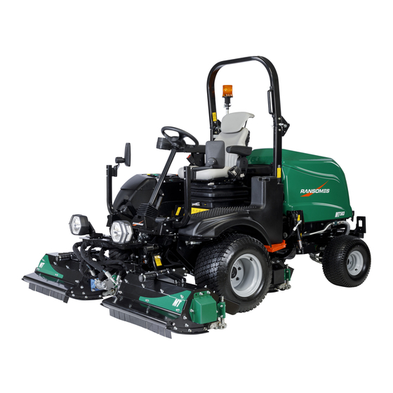
Ransomes MT503 Ride on Triple Cylinder & Flail Mower
Kubota D1803 - CR - TE5
With ROPS Series: NP
10007374
Product code:
With CAB Series: NQ
10007376
Product code:
WARNING: If incorrectly used this machine can cause severe injury. Those who use and maintain this
machine must be trained in its proper use, warned of its dangers and must read the entire manual before
attempting to set up, operate, adjust or service the machine.
®
WARNING
GB
United
Kingdom
10032876-A-GB
®
RJL AFCB
Advertisement
Table of Contents

Related Manuals for Ransomes MT503


Summary of Contents for Ransomes MT503
- Page 1 ® Safety, Operation & Maintenance Manual Ransomes MT503 Ride on Triple Cylinder & Flail Mower Kubota D1803 - CR - TE5 With ROPS Series: NP 10007374 Product code: With CAB Series: NQ 10007376 Product code: WARNING WARNING: If incorrectly used this machine can cause severe injury. Those who use and maintain this machine must be trained in its proper use, warned of its dangers and must read the entire manual before attempting to set up, operate, adjust or service the machine.
- Page 2 ©2021 Ransomes Jacobsen Limited. All Rights Reserved...
-
Page 3: Table Of Contents
1 CONTENTS SECTION ............PAGE SECTION ............PAGE INTRODUCTION Service Menu ............37 Important ..............5 Fault Log ...............37 Product Identification ..........6-7 Time Until Service ..........38 Guidelines For The Disposal Of Scrap Products ... 8 Vehicle Diagnostics ..........38 During Service Life ..........8 I/O Diagnostics ............39 End Of Service Life .......... - Page 4 1 CONTENTS SECTION ............PAGE SECTION ............PAGE Park Brake Release Valve ........63 ADJUSTMENT Free Wheel ............63 Traction Control Pedal .........102 Lighting Kit (Optional) ........... 64 Traction Boost / Weight Transfer Adjustment ..102 Seat Right Hand Arm Rest & Pod ......64 Cutting Cylinder To Bottom Blade Adjustment ..
-
Page 5: Introduction 2
INTRODUCTION 2 IMPORTANT __________________________________________________________ The Ransomes MT503 is a Diesel engined self propelled mower. The hydraulic systems are for the traction drive, the cutting unit lift and lower and cutting unit drives and steering. IMPORTANT: Ensure the maintenance indicated in this manual is conducted to make sure that the quality of cut is kept at a high level. -
Page 6: Product Identification
2 INTRODUCTION These instructions are the original instructions confirmed by Ransomes Jacobsen Limited. PRODUCT IDENTIFICATION ___________________________________________ Maximum front axle load in Kg (for machines being driven on the highway) West Road Ransomes Europark Unladen weight, (No cutting units or fuel (mass) in Kg... - Page 7 INTRODUCTION 2 ROPS Serial Plate Ransomes Jacobsen Ltd Weight of ROPS West Road Ransomes Europark Ipswich IP3 9TT Date Code England Standard Used Part Number Used on Product Serial Number ROPS Serial Plate Location The ROPS serial plate (C) is located at the base of the front of the ROPS main beam.
-
Page 8: Guidelines For The Disposal Of Scrap Products
“General discarded materials” area. • Do not burn discarded materials. Change the machinery records to show that the machine is not in service and is discarded. Supply this serial number to Ransomes Jacobsen Limited Warranty Department to close their records. en-8... -
Page 9: Parts Manual
INTRODUCTION 2 PARTS MANUAL ______________________________________________________ In compliance with the ISO14001 standard, Ransomes Jacobsen Limited does not send a paper parts manual with every product. To refer to a parts list for this mower you have two options: Website – www.ransomes.com. Select the “FIND A MANUAL” tab at the top, select a brand, product category and product. -
Page 10: Notes
2 INTRODUCTION NOTES en-10... -
Page 11: Safety 3
Know the location and correct operation of controls. Operators without experience must receive instruction from another person that knows the correct operation of the equipment before you operate the mower. Only use parts, accessories and attachments approved by Ransomes Jacobsen Limited. 3.1.1 SAFE OPERATION ___________________________________________________ Read the Operator’s Manual and other training material. -
Page 12: Operation
3 SAFETY Inspect the area where the equipment is operated. Remove all objects you can find before you operate. Be careful of obstructions above the ground (low tree limbs, electrical wires) and also underground obstacles (sprinklers, pipes, tree roots). Enter a new area carefully. Look for possible hazards. Inspect the cutting system before you start the mower. -
Page 13: Rops & Cab
ROPS/Cabin frame. Do not remove the ROPS/Cabin from the mower other than for maintenance access. Ensure to refit before use. Ransomes Jacobsen must approve any changes to the ROPS/Cabins. 3.1.5 SAFE HANDLING OF FUELS __________________________________________ The fuel and the fuel vapors are flammable. Use caution when you add the fuel to the mower. The fuel vapors can cause an explosion. -
Page 14: When You Put The Mower On A Trailer
DO NOT operate the machine if you have worn or damaged parts for safety. Replace damaged or worn decals. Only use parts, accessories and attachments approved by Ransomes Jacobsen. To decrease the fire hazard, remove materials that burn from the engine, muffler, battery tray and fuel tank area. -
Page 15: Important Safety Notes
By following all instructions in this manual, you increase the life of your machine and keep its maximum performance. Adjustments and maintenance must always be done by an approved technician. If a service is needed contact your authorized Ransomes Jacobsen Dealer or after sales for additional information or help. - Page 16 2006/42/EC Sections 3.2.2, Seating & 3.4.3, Rollover. (ANSI B71.4-2012 section 20.7) Ransomes Jacobsen Limited recommends that the owner/user of the machine completes a site specific risk assessment of the machine to find any conditions that do not follow this rule.
- Page 17 SAFETY 3 WARNING Vibration Exposure Limits Exposure limits are calculated as a combination of the vibration level (magnitude) of the tool and the Daily Exposure Time (Trigger Time). e.g. A product with 5m/s² vibration can be used up to 2 hours/day to reach the EAV and up to 8 hours/day to reach the ELV.
-
Page 18: Specifications
4 SPECIFICATIONS ENGINE SPECIFICATION ______________________________________________ Model: Kubota D1803-CR-TE5 Type: Vertical, water-cooled, 4-cycle diesel engine Number of Cylinders Bore & Stroke 87mm x 102.4mm Total Displacement 1.826 litres Combustion Chamber Direct injection type Rated output / kW / min (rpm) 37.0 / 2700 Speed*1 (HP / min (rpm) 49.6 / 2700 Max. -
Page 19: Dimensions & Weights
SPECIFICATIONS 4 DIMENSIONS & WEIGHTS _____________________________________________ Metric Imperial Width of Cut (Magna 250) 215cm 84.6In Width of Cut (MT Flail) 215cm 84.6In Overall Width (Cutting Mode with Magna 250) 240cm 94.5In Overall Width (Cutting Mode with MT Flail) 237cm 93.3In Overall Width (Transport Mode.Cutting Units set to 25mm Height of Cut.) Magna 250 168cm 66.1In... - Page 20 4 SPECIFICATIONS MT503 - Showing botth Cylinder and Flail Cutting Implements for illustrative purposes only. MT503 - Cylinder Cuttings Units MT503 - MT Flail Cutting Units MT503 with Cabin MT503 with ROPS folded en-20...
-
Page 21: Machine Specification
Rear Wheel Product Tyre Size Tyre Type Tyre Pressure Tyre Size Tyre Type Tyre Pressure MT503 OTR BKT LG306 1.37 - 1.72 bar OTR BKT LG306 1.37 - 1.72 bar 26 x 12.00 -12 20 x 10.00-8 Reinforced Tyre (20-25psi) -
Page 22: Vibration Level
Referenced to Hand/Arm: BS EN ISO20643:2008 Information Supplied for Physical Agents Directive 2002/44/EC By reference to: Hand/Arm Standards: BS EN ISO 5349-1 (2001) BS EN ISO 5349-2 (2002) MT503 with ROP’S Series NM Hand / Arm Acceleration Max. LH or RH Accelerations m/s² Level... -
Page 23: Noise Testing
The Lawnmower Standard BS EN ISO 5395:2013 Sound Pressure Standard EN ISO 3746:2010 MT503 - Fitted with Magna 250 Cylinder Cutting Unit: Measured Sound Pressure 82 dB(A) ± 1.24 LWA (ROPS Unit) Measured Sound Pressure 84 dB(A) ± 1.24 LWA (Cabin Unit - Door/Windows Closed) Measured Sound Pressure 87 dB(A) ±... -
Page 24: Cutter Specification
4 SPECIFICATIONS CUTTER UNIT SPECIFICATION _________________________________________ Magna 250 Construction Heavy duty welded pressed steel construction Blade Length 762mm (30”) Number of Blades 4 / 6 /8 Cylinder Diameter (New) 254mm (10”) Minimum Cylinder Diameter 235mm (9.25”) (Before Replacement) Height of Cut 12.7mm - 61mm (0.5”- 2.4”) Height of Cut Adjustment Adjustable screw system on rear roll... -
Page 25: Notes
SPECIFICATIONS 4 NOTES en-25... -
Page 26: Decals
5 DECALS SAFETY DECALS EC__________________________________________________ 4153197 19°+ 4321506 4324674 en-26... - Page 27 DECALS 5 009034920 Stay Clear of Hot Surfaces. 009034880 Caution, Fan blade, Do Not Open Or Remove Guards Whilst Engine In Operational. 009034940 Caution Rotating Blades. 009034900 Caution Drive Belt. Do Not Remove Safety Shields While Engine is Running. 4164860 Caution Hydraulic Oil.
-
Page 28: Instruction Decals Ec
5 DECALS INSTRUCTION DECALS EC ____________________________________________ CLASSIFICATION CJ-4 20mm 0.8 inch 26mm 1 inch 32mm 1.26 inch 38mm 1.5 inch 44mm 1.7 inch 50mm 2 inch 56mm 2.2 inch 62mm 2.4 inch 1.37 - 1.72 bar 20 - 25 psi TOTAL EQUIVIS ZS 46 en-28... - Page 29 DECALS 5 Description Beacon Parking Brake Horn Cutting Unit PTO Drive Throttle 4164861 - Traction Pedal, Forward / Reverse Power socket 12 volt Mow / Transport lever 009034770 - Guaranteed Sound Power Level 009039870 - Jack & Hook Point 4316687 - Engine Oil Classification 4286422 - Hydraulic Fluid 4323911 - Tyre Pressures 10029876 - Flail Height of Cut...
-
Page 30: Controls
6 CONTROLS OPERATOR WORKSTATION____________________________________________ ROPS Workstation 6.11 6.12 6.2A 6.18 Cabin Workstation 6.11 6.12 6.2A 6.18 en-30... -
Page 31: Instrument Panel
CONTROLS 6 CONTROL PANEL __________________________________________________ A:Starter Key Switch M:Right Hand Cutting Unit Position Lamp B:Throttle Control N:Centre Cutting Unit Position Lamp C:Park Brake Switch P:Left Hand Cutting Unit Position Lamp D:Hazard Warning Switch (Optional) Q:Traction Boost / Weight Transfer Switch E:Cutter Switch (PTO) R:Cutters (PTO) Indication Lamp F:4WD Reverse Assist... -
Page 32: Starter Key Switch
6 CONTROLS 6.2.A STARTER KEY SWITCH ______________________________________________ The Starter Key (A) must be turned clockwise to the 'start' position to start the engine. After starting, the key must be released and allowed to return automatically to the 'on' position for normal running. NOTE:The glow plugs will auto pre-heat depending on the coolant temperature before cranking begins. -
Page 33: Cutter Switch Pto
CONTROLS 6 6.2.E CUTTER SWITCH (PTO) ______________________________________________ Switches the Cutters On and Off when machine is in Mow mode (See Section 6.11). Push top of the PTO rocker switch to start the cutters. Push bottom of the PTO rocker switch to stop the cutters. 6.2.F 4WD IN REVERSE SWITCH____________________________________________ Engages 4 wheel drive whilst the vehicle is reversing. -
Page 34: Cruise Control Switch
6 CONTROLS 6.2.I CRUISE CONTROL SWITCH ___________________________________________ Cruise Control function will only operate whilst in cutting mode. When selected it will automatically hold the desired vehicle speed until further input by the operator is made. To engage cruise control: Automatic mode should be selected to enable cruise control. Press the rocker switch to engage the cruise function.To disen- gage cruise control press the rocker switch to disengage the cruise function. -
Page 35: Home Screen
If TST™ is not installed the TST™ icon will be crossed through. Ransomes Jacobsen recommends that the owner/user of the machine completes a site specific risk assessment of the area to be mown prior to operation of the machine. -
Page 36: Engine Start
6 CONTROLS 6.3.4 ENGINE START _____________________________________________________ When the Ignition Key is turned to the start position, this screen is shown. If the Park Brake is applied, the Cutting Unit Switch is in the OFF position, 1234 123.4 Hours the Foot Pedal is in the Neutral position, and the operator is in the seat, the engine will start. -
Page 37: Main Menu
CONTROLS 6 6.3.7 MAIN MENU ________________________________________________________ The arrow is moved up and down using Button 2 and 3, Button 4 then enters the selected page, Button 1 returns to the Home Screen. There will be four options within this menu: Main Menu Clock Service Menu... -
Page 38: Time Until Service
6 CONTROLS Button 4 takes the screen to the second Fault Log page which displays a list of the last 100 faults along with the Time, Date and Engine Hours that the fault occurred.The number in the top right hand corner shows the total Fault Log Time Date... -
Page 39: I/O Diagnostics
CONTROLS 6 6.4.3 I/O DIAGNOSTICS ___________________________________________________ These screens give access to various controller input and output Pin functions and their state to be used for diagnostic trouble shooting. Buttons 2 & 3 can be used to scroll between the pages, Button 1 returns to the Service Menu. -
Page 40: General
6 CONTROLS General Ref Module Function Note Number c1p06 Engine Ignition Key Input Main Controller c1p10 Park Brake Switch Input Main Controller c1p19 Hydraulic Oil Level Switch Input Main Controller c1p31 Engine Run Interlock Output Expansion Module c2p03 Reverse Beeper Output Main Controller c1p06 Seat Switch Input... -
Page 41: Cutting Units
CONTROLS 6 Cutting Units Ref Module Function Note Number c1p09 Left Hand Joystick Input Main Controller c1p16 Left Hand Position Sensor Input Expansion Module c2p04 Left Hand Float Solenoid Output Main Controller c1p39 Left Hand Lower Solenoid Output Main Controller c1p38 Left Hand Raise Solenoid Output c1p08... -
Page 42: Cutters
Left Hand Transport Lock Solenoid Output Expansion Module c2p09 Diverter Valve Output Main Controller c1p07 Cutting Circuit Pressure Switch Input Not used on MT503 Main Controller c1p24 Mow/Transport Speed Switch Input Not used on MT503 Main Controller c1p44 Traction Boost Solenoid Output... -
Page 43: Traction
CONTROLS 6 Traction Module Pin Number Function Note Main Controller c1p07 Cutting Circuit Pressure Switch Input Not used on MT503 Main Controller c1p24 Right Hand Wheel Speed Sensor Input Main Controller c1p27 Traction Pedal Signal B Input Main Controller c1p42... -
Page 44: Main Controller Miscellaneous Pins
6 CONTROLS Main Controller Miscellaneous Pins Module Pin Number Function Note Main Controller c1p01 Battery Negative Main Controller c1p04 CAN 0 Low Main Controller c1p09 Sensor Power Ground Main Controller c1p22 CAN 1 Shield Main Controller c1p49 Battery Positive Main Controller c1p02 Battery Positive Main Controller... -
Page 45: Main Controller Miscellaneous Pins Cont
Battery Positive c1p02 Battery Positive c1p05 CAN 0 Shield Expander Module c1p03 CAN 0 High Expander Module c1p06 to c2p02 Not used Not used on MT503 Main Controller c1p21 CAN 1 Low c1p03 CAN 0 High c1p12 Alarm Buzzer Output en-45... -
Page 46: Vehicle Modes
6 CONTROLS 6.5.2 VEHICLE MODES ___________________________________________________ The MT503 machine transmission operates in one of three selectable modes. In each mode the maximum vehicle speed and maximum engine throttle settings are predefined in the settings menu. (Section 6.5.6) Maximum defined Transport speed is available when Cutters are switched off. When Cutters are switched on only the predefined Mowing speed is achievable. -
Page 47: Pin
This screen gives access to the following parameters and machine functions that can be altered: • Cross Cut • Traction Boost • Inclinometer • Set Default Parameters • Change PIN • Flail \ Cylinder Mode The default owner’s Pin is 1001, however Ransomes Jacobsen recommend this is changed en-47... -
Page 48: Adapticut
6 CONTROLS 6.5.5 ADAPTICUT™ ______________________________________________________ AdaptiCut is a load sensing system that maintains optimum cutting performance by adjusting ground speed depending on the machine cutting system loading. It will automatically activate when the vehicle transmission is set to Automatic (A), the speed is set to Mow (Cutter Switch is on), Cruise is active, and the cutting system detects increased load. -
Page 49: Flail /Cylinder Mode
6.5.7 FLAIL \ CYLINDER MODE _____________________________________________ The MT503 cutting system is capable of providing power to both Magna 250 cutting cylinders and MT Series flail units. To ensure that these run at their intended speed it is important to ensure the machine’s cutting system is configured correctly. -
Page 50: Auto Idle
6 CONTROLS 6.5.9 AUTO IDLE _________________________________________________________ The throttle drops to idle when the Forward/Reverse pedal returns to neutral and the vehicle speed is set to Transport (Cutter Switch is off). When this is active the Auto Idle icon will be displayed on the screen. 6.5.10 CROSS CUT ________________________________________________________ Cross Cut function raises the cutting unit to a partially raised position, allowing the operator to avoid obstructions without having to fully lift the... -
Page 51: Inclinometer
CONTROLS 6 6.5.12 INCLINOMETER _____________________________________________________ Using the PIN Menu Buttons 2 and 3 to arrow up and down, and Button 4 to select Inclinometer and this gives you the option to Enable or Disable TST™. Inclinometer Note: If TST™ is installed, but disabled via the screen, the machine angle Disabled Enabled when greater than 14°... -
Page 52: Change Pin
6 CONTROLS 6.5.15 CHANGE PIN _______________________________________________________ Using the PIN Menu Buttons 2 and 3 to arrow down to the bottom of the list, and Button 4 to select Change Pin, this gives you the option to change from the default Owner’s PIN Number. Change Pin - Owner New PIN: * * * * Confirm: 1 _ _ _... -
Page 53: Warning Screens
If the vehicle angle decreases before either an Inhibit Cut or Stop Cut warning has been triggered. The angle at which this warning occurs varies with machine configuration as follows: • MT503 with ROPS – 19° • MT503 with Cab – 16° en-53... -
Page 54: Warning Slope Angle - Inhibit Cut
Button 4 to clear it). The angle at which this warning occurs varies with machine configuration as follows: • MT503 with ROPS – 21° • MT503 with Cab – 19° 6.6.4 WARNING SLOPE ANGLE – STOP CUT__________________________________... -
Page 55: Warning Engine Overheat
6.6.7 WARNING ENGINE FAULT ____________________________________________ When this screen is shown, there is an engine fault. Stop the engine as soon as possible and contact your local Ransomes Jacobsen Dealer. When this fault occurs the machine’s engine may automatically reduce the power available. -
Page 56: Warning Charge Filter Blocked
6.6.11 WARNING TILT SENSOR TECHNOLOGY (TST™) FAULT _______________ When this screen is shown, there is a fault with the TST™. Stop as soon as possible and contact your local Ransomes Jacobsen Dealer. 6.6.12 JOYSTICK FAULT _______________________________________________ When this screen is shown, there is a fault with the Unit Lift/Lower Control. -
Page 57: Emission Fault - Delta-P Sensor
DPF Differential Pressure or a fault with the sensor itself. The output from the engine may be reduced. Stop the engine as soon as possible and contact your local Ransomes Jacobsen Dealer. CONTROL 6.6.14 EMISSION FAULT – EGR NO... -
Page 58: Clean Dpf Ash
When this screen is shown, the engine controller (ECU) is reporting that the level of ash in the DPF (Diesel Particulate Filter) is in excess of 95% and therefore the DPF needs to be serviced. Contact your local Ransomes Jacobsen Dealer for information on the procedure for servicing the DPF. >95% 6.6.18... -
Page 59: Cutting Unit Lift / Lower Switch
CONTROLS 6 CUTTING UNIT LIFT / LOWER SWITCH ___________________________________ To lower the lift arms move the switch lever forward. To raise the lift arms move the switch lever rearwards. WEIGHT TRANSFER / TRACTION BOOST SWITCH ______________________ The switch will transfer weight hydraulically between the drive wheels and the cutting units. -
Page 60: Cutting Unit Position & Performance Indicator
6 CONTROLS CUTTING UNIT POSITION & PERFORMANCE INDICATOR LAMP _____________ These lamps illuminate green when the cutting unit is lowered to the ground and illuminates red when the engine begins to labour. If this happens the forward speed of the machine must be reduced until the lamp goes out. -
Page 61: Traction Pedal
CONTROLS 6 6.11 TRACTION PEDAL____________________________________________________ DRIVING To enable full forward transport speed, The vehicle needs to be set to either Automatic or Manual mode from the Main menu (Section.6.5.2) and the Cutter PTO switch off. (Section.6.2.E) 1. Release Brake - Make sure the Park Brake is released before you try to go forward or in reverse. -
Page 62: Steering Tilt Control
6 CONTROLS 6.12 STEERING TILT CONTROL _____________________________________________ When the operators seat is in the correct position to operate the Traction Pedal comfortably, push the small Foot Pedal (A) at the base of the steering column, and tilt the column backward or forward to the correct position. -
Page 63: Park Brake Release Valve
CONTROLS 6 6.15 PARK BRAKE RELEASE VALVE _______________________________________ The Park Brake Release Valve is situated under the footplate, on the left hand chassis rail. It is used to release the parking brake when the en- gine is not running To release the Parking Brake, •... -
Page 64: Lighting Kit (Optional)
6 CONTROLS 6.17 LIGHTING KIT (OPTIONAL) __________________________________________ Lighting Control Stalk No function. Pull towards operator to flash headlights. Move stalk down to indicate left turn. Move stalk up to indicate right turn. Horn NOTE: Daylight Running Lamps will operate when ignition is in the run position When the lighting kit is fitted a brake light function is available. -
Page 65: Cab Controls
CONTROLS 6 6.6.19 CABIN CONTROLS ________________________________________________ Left Turn Signal Lamp Working Lights Switch (Optional) Beacon Switch Front Screen De-Mist Switch Rear Screen Wiper Switch (Optional) Front Screen Wash Switch Front Screen Wiper Switch Right Turn Signal Lamp Fan Control Air Conditioning Control Temperature Control Fuse Holder Fuse Holder... -
Page 66: Operation
7 OPERATION DAILY INSPECTION_________________________________________________ CAUTION The daily inspection should be performed only when the engine is off and all fluids are cold. Lower cutting units to the ground, engage Park Brake, stop engine and remove Ignition Key. 1. Perform a visual inspection of the entire machine, look for signs of wear, loose hardware and missing or dam- aged components. -
Page 67: Operating Procedure
OPERATION 7 Cutter Engage Test Operator Seated Traction Pedal Park Brake Switch Engine Starts (PTO) Switch Out of Neutral Neutral Lift your weight off the seat. The cutting implement PTO will disengage within 3 seconds. Lift your weight off the seat. The engine must stop after 3 seconds. OPERATING PROCEDURE ___________________________________________ WARNING Never operate the equipment with the operator presence... -
Page 68: Fitting Cutting Units
7 OPERATION FITTING CUTTING UNITS ____________________________________________ Cutting Unit Mounting - Magna 250 Front units: 1. Lower the lift arm (A). If fitted remove Shaft (B) from Clamp Plate 2. Apply grease to shaft (B) to ease fitting. Insert the shaft through pivot mounting bracket (H). -
Page 69: Interchanging Cutting Units
INTERCHANGING BETWEEN FLAIL AND CYLINDER UNITS _______________ The MT503 has option of interchangeable Cutting Units. To convert the machine between either Flail or Cylinder Cutting Units the following procedure must be followed: 1. Remove existing three cutting units if fitted. Make note of Hydraulic motor orientation on removal for future reference. -
Page 70: Operation Of The Machine
7 OPERATION PIN Menu Flail\Cylinder Mode Traction Boost Flail Inclinometer Cylinder Set Default Parameters Change PIN Flail \ Cylinder Mode OPERATION OF THE MACHINE _______________________________________ Read the Safety Instructions.Section 3. BEFORE OPERATING FOR THE FIRST TIME • Check and adjust tyre pressure, if necessary, see section 4.3 Specification. •... -
Page 71: Mowing
Move the throttle control lever to the slow position. Turn the ignition key to the OFF position and remove the key. Use the Ransomes Jacobsen “Cutting Unit Tool” part number 4184540, or stout stick, put into the cylinder between the blades. -
Page 72: Backlapping
• Backlapping must only be done by approved personnel. • Ransomes Jacobsen recommend that backlap paste is only applied to the cylinder when it is stationery, the engine is off and the park brake applied. • When applying backlap paste the cylinder must only be rotated by appropriately sized piece of wood and not by hand. -
Page 73: Cooling Fan Operation
OPERATION 7 7.13 COOLING FAN OPERATION __________________________________________ The MT503 is equipped with an engine cooling fan that can be reversed to clear debris from the hood intake grilles. The fan reversal function operates in one of three modes – Disabled – The fan operates in normal forwards direction only and ·... -
Page 74: Transporting On A Trailer Or Flat Bed
7 OPERATION 7.14 TRANSPORTATION ON A TRAILER OR FLATBED________________________ 1. The machine has tie-down loops front (A) and rear (B). Fasten the mower to the transport vehicle. 2. Make sure that all tie down straps are tight. Make sure that the units are locked in the transport position. Check the fuel and hydraulic tank caps are tight. -
Page 75: Mowing On Slopes
ROPS to comply with the Machinery Directive 2006/42/EC sections 3.2.2, Seating & 3.4.3, Rollover Ransomes Jacobsen Limited recommends that a local risk assessment is completed by the owner/user of the machine to determine the risks associated with working on slopes. -
Page 76: Maintenance And Lubrication
8 MAINTENANCE AND LUBRICATION MAINTENANCE & LUBRICATION _____________________________________ GENERAL MAINTENANCE AND LUBRICATION CHART Interval Item Section First 50 Hours Change Hydraulic Charge Filter Element or earlier if screen indicates. Daily Visual inspection for damage or wear 10 Hours ... - Page 77 MAINTENANCE AND LUBRICATION 8 8.10 A, C & D 8.10.2 8.12 en-77...
-
Page 78: Engine Service Interval
8 MAINTENANCE AND LUBRICATION 8.1.1 ENGINE SERVICE INTERVAL _____________________________________________ ENGINE SERVICE INTERVAL CHART Interval Item Section Daily 8.2.1 Check engine oil level. 10 hours 6.3.4 Check fuel level. Check coolant level. Check auxiliary belt tension. 8.11 Press together the air cleaner dust valve. - Page 79 MAINTENANCE AND LUBRICATION 8 Interval Item Section Replace oil separator related rubber piping. Replace DPF related rubber piping. Replace intake air line and suction air pressure takeout rubber piping. Replace boost sensor pressure rubber piping. Replace EGR cooler rubber piping.
-
Page 80: Engine
The operation and maintenance during the first 50 hours of a new engine can make a difference to the performance and life of the engine. During the first 50 hours of operation, Ransomes Jacobsen recommends the following. • Allow the engine to reach a temperature of at least 60° C (140° F) before operation at full load. -
Page 81: Engine Lubrication
MAINTENANCE AND LUBRICATION 8 8.2.1 ENGINE LUBRICATION _____________________________________________ Check Engine Oil Level Check the engine oil level before you start or at least five minutes after you stop the engine. Park the machine on level ground, remove the dipstick (A), clean with a cloth and replace in position. -
Page 82: Lubrication Of Cutting Units And Lift Arms
8 MAINTENANCE AND LUBRICATION LUBRICATION OF CUTTING UNITS AND LIFT ARMS _____________________ Lubricate the cutting Units and lift arm pivots as per service schedule. Grease point locations can be found at the following locations. Front Pivot Arm (A), Centre Pivot Arm (B) Cutting Unit Mounting (C). -
Page 83: Flail Cutting Unit Maintenance
MAINTENANCE AND LUBRICATION 8 8.3.1 FLAIL CUTTING UNIT MAINTENANCE _________________________________ Daily Inspection Check condition of the blades & hardware every day prior to cutting. Remove any debris or foreign objects from around flail blades. • Check the blade (A) and fixings are secure. Ensure the Nut (D), bolt (C) and shackles (B) are securely attached. -
Page 84: Engine Alternator Belt
8 MAINTENANCE AND LUBRICATION ENGINE ALTERNATOR BELT ________________________________________ Check and adjust the alternator belt The alternator belt tension is adjusted to prevent the stress on the alternator bearings and to prevent movement on the alternator pulley. Use the procedure shown below to check the belt tension at the center of the belt between crank shaft and alternator pulleys. - Page 85 Replace the clamps and hoses (see maintenance chart). Have your Ransomes Jacobsen Dealer check the cooling system if you need to add coolant more than one time a month or you add more than1 litre of coolant at a time.
-
Page 86: Hydraulic System
8 MAINTENANCE AND LUBRICATION HYDRAULIC SYSTEM ______________________________________________ Drain and replace the hydraulic oil if one of the following occur. • Major Component failure (System Flush recommended) • Water or foam is in the hydraulic fluid • The hydraulic fluid has a rancid odour (indication of high heat) •... -
Page 87: Hydraulic System Flushing
Charge Pressure Port - Located under operators platform on left hand chassis rail. Transmission Forwards - Located under the Exhaust bulkhead, accessible from underneath the machine. NOTE: Any hydraulic related issues contact your Ransomes Jacobsen dealer for a full fault diagnosis. en-87... -
Page 88: Hydraulic Filter
8 MAINTENANCE AND LUBRICATION HYDRAULIC FILTER ________________________________________________ The hydraulic system is protected by a 10 micron filter (A). Flow through the filter is monitored while you operate the mower. When the difference in hydraulic pressure across the filter is greater than 16 to 20 psi (1.1 to 1.4 BAR), the hydraulic oil filter warning light on the combination gauge will illuminate. -
Page 89: Fuel
MAINTENANCE AND LUBRICATION 8 8.10 FUEL ____________________________________________________________ Diesel fuel is flammable. Use caution when you add the fuel to the mower. Only use an approved container. The spout on the container must fit inside the fuel filler neck. Never use the containers that are not approved to keep or transfer fuel. - Page 90 8 MAINTENANCE AND LUBRICATION Water Separator If water is not removed from the fuel, damage to the fuel-injection system can occur. When water in fuel icon is displayed or at service 1234 123.4 Hours interval, drain the water from the water separator. Stop the engine.
-
Page 91: Fuel Pickup Filter
MAINTENANCE AND LUBRICATION 8 8.10.2 FUEL PICKUP FILTER ______________________________________________ It is advisable that the Fuel Pickup Mesh Filter (A) is cleaned on a periodic basis. (Reference 8.1.1) Should the machine exhibit fuel starvation issues then the Mesh Filter should be checked and cleaned for contamination. To clean the Filter Mesh, Unscrew the Fuel Pickup cap and withdraw the Fuel Pickup Sender unit. -
Page 92: Battery
8 MAINTENANCE AND LUBRICATION 8.12 BATTERY _________________________________________________________ Before you service the battery, make sure the ignition switch is in the OFF position and the key is removed. CAUTION When you service the battery, always use the tools with insulation, wear protective glasses and protective clothing. -
Page 93: Charge The Battery
MAINTENANCE AND LUBRICATION 8 8.12.1 CHARGE THE BATTERY ______________________________________________ Read the battery charger manual for specified instructions on the operation of the charger. WARNING Charge the battery in an area with good airflow. The battery can release hydrogen gas that is explosive. To prevent an explosion, keep any device that can cause sparks or flames away from the battery. -
Page 94: Engine Exhaust
8 MAINTENANCE AND LUBRICATION 8.14 DIESEL PARTICULATE FILTER _______________________________________ During operation of the mower, the level of particle material will increase in the Diesel Particulate Filter (DPF) system. The periodic Regen of the DPF system is needed to remove particle material. During an Active or Parked Regen, the engine will use more fuel. -
Page 95: Hydraulic Hoses
MAINTENANCE AND LUBRICATION 8 8.15 HYDRAULIC HOSES _______________________________________________ WARNING To prevent injury from the hot, high pressure oil, never use your hands to check for oil leaks. Use paper or cardboard to find leaks. The hydraulic fluid pressure can have enough force to enter your skin. If hydraulic fluid has entered your skin, please seek medical attention as soon as possible. -
Page 96: Wheel Mounting Procedure
8 MAINTENANCE AND LUBRICATION 8.17 WHEEL MOUNTING PROCEDURE ______________________________________ WARNING Make sure the mower is parked on a solid and level surface. Never work on a mower that is supported only by the Jack. Always use Axle Stands. If only the front or rear of the mower is lifted, put the chocks in front of and behind the wheels that are not lifted. -
Page 97: Wheel And Steering Alignment / Adjustment
MAINTENANCE AND LUBRICATION 8 8.19 WHEEL ALIGNMENT PROCEDURE ____________________________________ 1. Park machine on a flat and level surface, turn the steering wheel so that the steering ram shafts are equal on both sides of the ram (Dimensions ‘C’ and ‘D’ below). Rear Axle illustrated without wheel hubs fitted Alignment tool in illustration may vary to tool provided under part number 4390586. -
Page 98: Steering Rod And Steering Link Check
8 MAINTENANCE AND LUBRICATION 8.19.1 STEERING ROD AND STEERING LINK CHECK _________________________ Figure 1 - Steering Link Test Movement FRONT REAR 1. With the steering in a straight position and the Alignment Tools still fitted (after the Wheel Alignment procedure) inspect the “free movement” of the steering linkage can be checked to see if it is within specification. -
Page 99: Machine Maintenance
MAINTENANCE AND LUBRICATION 8 8.20 MACHINE MAINTENANCE ___________________________________________ Other Regular Service • Verify proper operation of safety interlock switches (Section 7.2) • Ensure nuts and bolts remain tight. • visually inspect for hydraulic leaks. • Keep engine bay clear of debris. •... -
Page 100: Folding Rops
The Machinery Directive, 2006/42/EC sections 3.2.2, seating & 3.4.3, rollover. (ANSI B71.4-2012: Sect;20.7) Ransomes Jacobsen Limited, recommend that the owner operator of the machine complete site specific risk assessment on the machine to find any conditions that do not follow this rule. - Page 101 MAINTENANCE AND LUBRICATION 8 NOTES en-101...
-
Page 102: Traction Control Pedal
9 ADJUSTMENTS TRACTION CONTROL PEDAL _______________________________________ The LPV transmission pump has an internal neutralizing mechanism which cannot be adjusted. If the machine does however creep carry out the following. Lift and support machine so that both front and rear wheels are off the ground and free to rotate. Remove ball joint from pump lever to allow pump to neutralize. -
Page 103: Cutting Cylinder To Bottom Blade Adjustment
ADJUSTMENTS 9 CUTTING CYLINDER TO BOTTOM BLADE ADJUSTMENT_______________ To check that the cutting cylinder is set to the bottom blade correctly, hold a piece of thin paper between the edge of the blade and the spiral cutters and turn the cylinder manually. The paper must be cut cleanly along the total length of the bottom blade, if not, some adjustment may be necessary, BUT DO NOT OVERTIGHTEN. -
Page 104: Cutting Cylinder Height Adjustment
9 ADJUSTMENTS CYLINDER HEIGHT OF CUT ADJUSTMENT ____________________________ TO ADJUST: Turn adjuster (A) at the rear of the unit clockwise to reduce the height of cut, or anticlockwise to increase the height of cut alternately. The grooves (B) are used as an rough indicator for setting the roll parallel. -
Page 105: General Instructions For Grammer Seats
ADJUSTMENTS 9 GENERAL INSTRUCTIONS FOR GRAMMER SEATS____________________ • The operating instructions must be read in full before use. • The driver’s seat may only be fitted, serviced and repaired by specialist personnel, In accordance with national regulations and the vehicle manufacturer’s fitting instructions. •... - Page 106 9 ADJUSTMENTS Adjustments must not be made while driving After removal of the backrest upholstery, the backrest frame must be supported, for example held in place, before the backrest adjuster is operated. If you fail to do so, there is a danger that the backrest frame may jerk forward and cause injury.
-
Page 107: Seat (Grammer Msg85)
ADJUSTMENTS 9 SEAT (GRAMMER MSG85) ________________________________________ WARNING The Operator weight must be set to the actual weight of the Operator. Safety Systems will be compromised if this is not done. The seat can be adjusted for operator's weight and leg reach to provide a comfortable position for operating the machine. -
Page 108: Air Suspension Seat (Grammer Msg75-521)
9 ADJUSTMENTS AIR SUSPENSION SEAT (GRAMMER MSG75-521) _____________________ 9.9.1 WEIGHT ADJUSTMENT ___________________________________________ The seat is adjusted for the driver’s weight by pulling or pressing the lever for seat weight adjustment and with the driver sitting on the seat. The driver’s weight is adjusted correctly when the arrow is in the middle clear area of the viewing window. -
Page 109: Backrest Extension
ADJUSTMENTS 9 9.9.3 BACKREST EXTENSION __________________________________________ The backrest extension can be individually adjusted by pulling it upwards or pushing it downwards over the various locking increments up the end stop. To remove the backrest extension, pull it upwards over the end stop. 9.9.4 LUMBAR SUPPORT ______________________________________________ The lumbar support increases both the seating... -
Page 110: Armrest Adjustment
9 ADJUSTMENTS 9.9.6 ARMREST ADJUSTMENT * ________________________________________ The inclination of the armrests can be modified by turning the adjustment knob. When turning the knob to the outside (+) the front part of the armrest will be lifted, when turning the knob to inside (-) it will be lowered. -
Page 111: Notes
ADJUSTMENTS 9 NOTES en-111... -
Page 112: Accessories
10 ACCESSORIES 10.6 ROTARY BEACON KIT ____________________________________________ Kit number 10006946 - Standard 10007714 - R65 Compliant. 10.7 LIGHTING KIT __________________________________________________ Kit Number: Light Kit 10007073 (UK) Light Kit 10013198(EU) en-112... -
Page 113: Storage Basket Kit
ACCESSORIES 10 10.8 STORAGE BASKET KIT ___________________________________________ Kit number 10009326 Maximum capacity per rack is 5kg. 10.9 TILT SENSOR TECHNOLOGY (TST™) _______________________________ TST™ kit number 10009298 10.10 MIRROR KIT ____________________________________________________ Mirror Kit 10012082 en-113... -
Page 114: Cutting Units
10 ACCESSORIES 10.10 CUTTING UNITS _________________________________________________ LMAC403-LP MAGNA 250 x 4K FX-RHD (HAND SPANNER) LMAC404-LP MAGNA 250 x 6K FX-RHD (HAND SPANNER) LMAC405-LP MAGNA 250 x 8K FX-RHD (HAND SPANNER) LMAC403-RP MAGNA 250 x 4K FX-LHD (HAND SPANNER) LMAC404-RP MAGNA 250 x 6K FX-LHD (HAND SPANNER) LMAC405-RP MAGNA 250 x 8K FX-LHD (HAND SPANNER) LMAC403-C... -
Page 115: Problem Solving 11
PROBLEM SOLVING 11 11.1 PROBLEM SOLVING GENERAL ____________________________________ Symptoms Possible Causes Action Glow plug has not timed out Reset ignition switch and allow glow plug to time out before cranking engine. Battery low on charge or Inspect condition of battery and battery connections. defective. -
Page 116: Quality Of Cut
12 QUALITY OF CUT 12.1 QUALITY OF CUT PROBLEM SOLVING ______________________________ If required perform a “test-cut” to assess the performance of the mower before you begin the repairs. When the work is completed, repeat the “test-cut” to check the mower performance. The following items must be checked and set correctly to make sure of an effective assessment. -
Page 117: The Step Cut
QUALITY OF CUT 12 12.2 STEP CUTTING __________________________________________________ “Step cutting” occurs when the grass is cut higher on one side. The cause is mechanical wear or incorrect setting of the roller or deck caster. TN0221 NOTE: Arrow indicates direction of travel. Possible Cause Correction The HOC (height-of-cut) settings are different between... -
Page 118: Scalping
12 QUALITY OF CUT 12.3 SCALPING______________________________________________________ “Scalping” is a condition in which some areas are cut shorter than the set height of cut. This results in very short grass or brown areas. TN0222 NOTE: Arrow indicates direction of travel. Possible Cause Correction The HOC (height-of-cut) settings are too low for the Check and adjust the HOC settings. -
Page 119: Stragglers
QUALITY OF CUT 12 12.4 STRAGGLERS __________________________________________________ “Stragglers” are separated blades of incorrectly cut grass. TN0223 NOTE: Arrow indicates direction of travel. Possible Cause Correction The cutting blades are blunt. Replace or sharpen blades. Cutting Speed to fast for grass conditions. Decrease the cutting speed. -
Page 120: Streaks
12 QUALITY OF CUT 12.5 STREAKS ______________________________________________________ A streak is a strip of longer grass in the cutting area. The cause is a damaged blade. TN0224 NOTE: Arrow indicates direction of travel. Possible Cause Correction Damaged or worn blades. Replace the blades. Turning sharply whilst cutting. -
Page 121: Windrowing
QUALITY OF CUT 12 12.6 WINDROWING___________________________________________________ “Windrowing” is an increase of cut grass arranged in rows in the discharge area of the cutting units, this appears as cut grass in the direction of travel. TN0225 NOTE: Arrow indicates direction of travel. Possible Cause Remedy The Height of grass is being reduced by too much in... -
Page 122: Clumping
12 QUALITY OF CUT 12.7 CLUMPING _____________________________________________________ “Clumping.” This problem is identified by the appearance of clumps of grass in the discharge area. TN1281 Possible Cause Correction Front edge of units bulldozing cut grass, between Clean rollers of grass build up, consider increasing blades and rear roller and anti-scalp skids. -
Page 123: Insufficient Mulch
QUALITY OF CUT 12 12.8 INSUFFICIENT MULCHING ________________________________________ “Insufficient Mulching.” This problem is identified by long lengths of cut grass not sufficiently chopped. Mulched Non Mulched TN1280 Possible Cause Correction Worn blades. Sharpen or replace cutting blades Cutting at more than the recommended speed. Decrease the cutting speed. -
Page 124: Inconsistent Uncut Patches
12 QUALITY OF CUT 12.9 INCONSISTENT UNCUT PATCHES __________________________________ “Inconsistent Uncut Patches.” This problem is iden- tified by long tufts of random uncut grass. TN1278 Possible Cause Correction Damaged or missing blades. Check and replace damaged blades or try Eliminator blades. Cutting at more than the recommended speed. -
Page 125: Torn Crowns
QUALITY OF CUT 12 12.10 TORN CROWNS _________________________________________________ “Torn Crowns” This problem is identified when clumps of grass (Crowns) are torn up rather than cut. TN1234 Possible Cause Correction Too much material. Cut more frequently, increase HOC. Worn blade edge. Sharpen or Replace damaged blades / Sharpen cylinder. -
Page 126: Laying Uncut Grass
12 QUALITY OF CUT 12.11 LAYING UNCUT GRASS___________________________________________ “Laying uncut grass.” This problem is identified by areas of grass that have been left uncut and laid flat. TN1234 NOTE: Arrow indicates direction of travel. Possible Cause Correction Mowing (ground) speed is too fast. Cut more frequently, increase HOC. -
Page 127: Electrical Fuses & Relays
SCHEMATICS 13 13.1 ELECTRICAL FUSES & RELAYS____________________________________ Replacement Fuses Fuse Tester 5A 7.5A 10A 15A 20A 25 Fuse Removal Tool B/LAP SPARE ENGINE FLASHER IGNITION GLOW PLUGS START TESTING A FUSE In the top right hand corner there is a tool that can be used to remove a fuse from its location. The tabs on the fuse should then be inserted into the slots that can be seen in the top RH corner so that they touch the sides of the hole. - Page 128 13 SCHEMATICS FUSE NO. RATING FUNCTION 40 Amp Glow Plugs 70 Amp Ignition On 7.5 Amp Hazard Lights (Optional) 10 Amp Starter 25 Amp Engine Master 5 Amp EGR Valve 7.5 Amp Fuel Pump 10 Amp Engine Sensors 20 Amp Engine Controller 5 Amp Engine Controller Start Signal...
-
Page 129: Torques
TORQUES 14 TORQUES ______________________________________________________ FINE PITCH METRIC THREADS COARSE PITCH METRIC THREADS Grade Grade Grade Grade Grade Grade Grade Grade Grade Grade (mm) 10.9 12.9 (mm) 10.9 12.9 (Nm) (Nm) (Nm) (Nm) (Nm) (Nm) (Nm) (Nm) (Nm) (Nm) 1055 1266 1152 1327 1593... - Page 130 14 TORQUES NOTES en-130...
-
Page 131: Guarantee
GUARANTEE ___________________________________________________________ WARRANTY Warranty is subject to specific terms and conditions, e.g. wearing parts, unapproved modifications, etc. are not included. For a full set of warranty conditions, contact your local dealer or distributor. NOTICE The use of components not provided by the manufacturer under this warranty or maintenance or repair that is improperly or incorrectly performed may void this warranty. - Page 132 Cert No. FS609275 Cert No. EMS609276 Cert No. OHS609277 United Kingdom Ransomes Jacobsen Limited West Road, Ransomes Europark, Ipswich, IP3 9TT English Company Registration No. 1070731 T: +44 1473 270000 W: www.ransomes.com Europe office Ransomes Jacobsen France 3 Chemin des Silos...
Need help?
Do you have a question about the MT503 and is the answer not in the manual?
Questions and answers