Table of Contents
Advertisement
Quick Links
Dear Customer,
Thank you for choosing us and showing your faith in the
Combilift range of products. With this Combilift Product
you now own a machine designed by our team of
experienced engineers using the most up to date design
techniques and technology with the sole aim of
producing a machine that is efficient, reliable, safe and
the right tool for your businesses material handling
needs. The Combilift product possesses a vast range of
multi-functional application possibilities that make it one
of the leading products in the material handling industry.
This Manual contains all of the information you will
require to operate your Combilift product safely and
efficiently. It is essential that this manual remain with the
machine at all times. It is essential that the operator read
this manual before attempting to operate the Combilift.
Always follow all safety instructions laid out in this
manual
All instructions, prohibitive or otherwise, found in this
manual should be adhered to at all times. They are there
to protect your life and the lives of others.
Always perform the Daily Inspection as indicated in
this manual and follow the guidelines on service
intervals.
www.combilift.com
Combilift Ltd
Advertisement
Table of Contents

Related Manuals for CombiLift C25000


Summary of Contents for CombiLift C25000
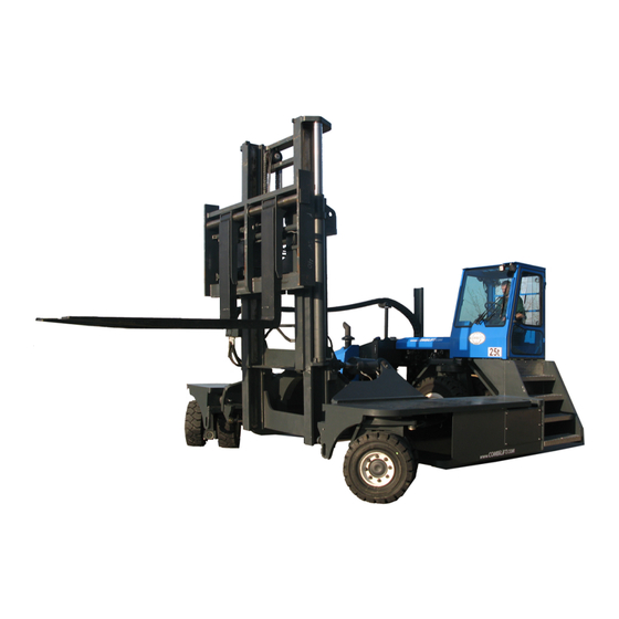
- Page 1 The Combilift product possesses a vast range of multi-functional application possibilities that make it one of the leading products in the material handling industry.
-
Page 2: Table Of Contents
C25000 O&S Manual Contents Section 1: Machine layout and Operator Controls ....3 1.1: Machine Overview and Components ............. 3 1.2: Operator Controls & Display Layout ............. 3 1.3: Operator Controls & Display Descriptions ............ 5 ... - Page 3 6.5: Fuses ......................57 6.6: Relay Layout ....................58 6.7: Combilift Electric Circuit ................60 6.8: Hydraulic Functions Circuit ................. 65 6.9: Hydraulic Drive Circuit ................66 6.10: PLC Details ....................
-
Page 4: Machine Layout And Operator Controls
Section 1: Machine layout and Operator Controls It is essential before you start operating the Combilift to be familiar with the main components and controls of the machine, their function and where they are located. Figure 1.1 below indicates all of the major components of the Combilift and figure 1.2 on the following page indicates all of the operator... - Page 5 C25000 O&S Manual Control Layout 1. Fuse Box 2. Engine Temperature Gauge 3. Hour Meter 4. Windscreen Wiper Switch 5. Cabin Fan Switch (Optional) 6. Heater Fan Switch (Optional) 7. Joystick On/Off Switch (If Fitted) 8. Fuel Gauge 9. Work Lights Switch 10.
-
Page 6: Operator Controls & Display Descriptions
C25000 O&S Manual 1.3: Operator Controls & Display Descriptions Now that the layout of the operator controls has been identified, the next step is to detail how the controls function. Ignition Switch: This is a three-position key switch located on the dash, which isolates the electrical system when in the off position. - Page 7 C25000 O&S Manual Work Lights Switch: This is a three position rotary switch located on the dash Position 0 – Lights Off Position 1 – Front Lights On Position 2 – Front & Side Work Lights On Joystick On/Off Switch (If Fitted): ...
- Page 8 C25000 O&S Manual Battery Charge Indicator Light This charging lamp indicates whether the alternator is charging the system or not. With the key switch turned ON and the engine not running, this red charge lamp should illuminate. If the charging lamp remains illuminated with the engine running, it indicates a malfunction of the charging system or associated components.
- Page 9 C25000 O&S Manual Carousel Indicator Light The carousel indicator light is only used when the machine is in sideward mode. When the front wheels are steered in to a certain position, the carousel indicator light will illuminate. It is at this point that the carousel mode is activated and the machine can turn on its own axis.
- Page 10 C25000 O&S Manual Cabin Fan (Optional) Switch This is a 2 position rotary switch located on the dash. Turning it to the on position activates the cooling fan located in the top right hand corner of the cabin. See Item 5 in figure 1.2 on page 5.
- Page 11 C25000 O&S Manual Accelerator Pedal The accelerator pedal is located on the floor on the right hand side of the steering column. The accelerator pedal provides the operator control of the truck speed. To INCREASE truck speed, DEPRESS pedal.
- Page 12 C25000 O&S Manual Seat Adjustment It is the responsibility of the Operator to ensure that the seat is adjusted according to operator weight, height etc before operating the truck. ALWAYS report any malfunctioning of the seat adjustments immediately.
-
Page 13: Fork Control Joystick
C25000 O&S Manual 1.4: Fork Control Joystick Component Layout Lift Control To raise forks, pull joystick back. To lower forks, push joystick forward. TILT Mast Extension/ Retraction SCROLL WHEEL To extend mast, roll Reach scroll REACH wheel forward. - Page 14 Combilift have a number of standard functions that can be fitted to the truck and operated via the auxiliary button and joystick. These include: Fork Positioner / Side shift / Telescopic Forks / Lift Drop Forks ...
-
Page 15: Operating Instructions And Conditions
- two weights on opposite sides of a fulcrum. In this case, the load on the forks must be balanced by the weight of the Combilift. The location of the centre of gravity of both the Combilift and the load is a major factor. - Page 16 C25000 O&S Manual The centre of gravity and therefore stability is also affected by the size, weight, shape and position of the load; the height to which it is raised; extension of mast forward and backward; tilt and side shift. Truck movement such as acceleration, braking, turning and uneven surfaces will also affect truck stability.
-
Page 17: Load Chart
2.4: Operator Qualification and Responsibilities The operator of the Combilift must be qualified to operate the truck through successful completion of a training program delivered by Combilift Driver training personnel or a Combilift authorised training organisation. - Page 18 C25000 O&S Manual Report any operational problems that may develop, (damaged pallets, ground surface breaking up etc.) which could not only reduce safety but also cause damage to the truck. Never attempt to exceed your truck’s handling capacity and take all precautions to ensure the safety of others as well as yourself.
-
Page 19: Entering And Exiting The Operator Cabin
C25000 O&S Manual 2.5: Entering and exiting the operator Cabin When entering or exiting the Operator cabin of the Combilift, always use a three point contact method to avoid slips and falls. The three point contact method is applied by keeping 3 of the bodies 4 limbs (hands & feet) in contact with the machine. -
Page 20: Moving Off
C25000 O&S Manual 2.7: Moving Off Ensure that the forks are as low as possible. If loaded, rest the load on the platforms where possible. Select forward, reverse, right or left with the Direction Control Joystick. Parking brake must be applied before change in mode is selected. -
Page 21: Stopping
C25000 O&S Manual Parking brake must be applied before change in mode is selected. Do not press the brake pedal while a change in mode is being selected. Move the direction control switch from left/right into the required forwards direction. -
Page 22: When Loading In Forward Mode
C25000 O&S Manual Double fork load if necessary until load is tight against face of forks. (See section on “double forking”) Tilt rearward to secure the load. Raise load above platform height. Retract mast fully. Lower forks until load is just above platform height. Rest the load on the platforms where possible. -
Page 23: Double Forking
NOTE The lift capacity of the Combilift is reduced if the forks are not fully engaged. To Double Fork a Load: Raise the load slightly and retract the mast sufficiently to bring the load closer to the machine. -
Page 24: Adjusting Load Forks (Optional Fork Positioning)
C25000 O&S Manual 2.20: Adjusting Load Forks (Optional Fork Positioning) Forks should be spaced as far apart as the load being moved will allow. Both forks should always be the same distance from the centre of the fork carriage. - Page 25 C25000 O&S Manual Ground Surface: Floor, road and yard surfaces should be of adequate load capacity, firm, smooth and level. Approaches to kerbs, railway crossings etc. should also be firm, smooth and adequately ramped to prevent possible displacement. Aisle Dimensions: Aisles should be arranged to eliminate corners, angles, inclines, steep ramps, narrow passages and low ceilings.
- Page 26 If the temperature falls below or rises above this range discontinue operation of the machine in order to prevent damage to various components. For operation outside these temperatures, please consult your Combilift partner as special modifications and lubricants are required. C25000-OM-EN-05...
- Page 27 C25000 O&S Manual Oil, Fuel and Coolant: Any leaking or spilled oil, fuel or coolant must be cleaned up immediately and the source of the leak repaired to avoid: Environmental hazards Fire hazards Slip hazards Personal injury hazards Do not attempt to perform repairs to the hydraulic system until any residual hydraulic pressure has been relieved.
- Page 28 3. Maintain a safe distance from the edge of ramps, platforms, or other similar working surfaces. 4. Never attempt to move a trailer with the Combilift truck. C25000-OM-EN-05...
-
Page 29: Daily Checks
C25000 O&S Manual Section 3: Daily Checks Please refer to the John Deere engine manual that is supplied with Combilift truck in relation to all Engine checks and activities. NTRODUCTION Before commencing the daily checks, ensure that the ignition switch is turned to the ‘OFF’... -
Page 30: Coolant Level
C25000 O&S Manual 3.4: Coolant Level Adding Coolant CAUTION: Explosive release of fluids from pressurised cooling system can cause serious burns. Shut off engine. Only remove filler cap when cool enough to touch with bare hands. Slowly loosen cap to first stop to relieve pressure before removing completely. -
Page 31: Fuel Tank
C25000 O&S Manual 3.6: Fuel Tank The following checks should be made: Check the tank for leaks, damage, rust and other corrosion. Check that the filler cap and sender unit are leak free, secure and functioning correctly. 3.7: Automatic Fan Belt Tensioner Belt drive systems equipped with automatic (spring) belt tensioners cannot be adjusted or repaired. -
Page 32: Safe Operation
C25000 O&S Manual Section 4: Safe Operation 4.1: Safe Operation Combilift will not assume any liability for injuries or damage arising from or caused by the removal of any safety devices from their vehicles by the user. Fully trained, qualified and authorised drivers must only operate combi-Lift forklift trucks. -
Page 33: Safe Driving
C25000 O&S Manual 4.2: Safe Driving Before moving off, look around and when clear, commence driving without causing inconvenience to other aisle users. Remember that pedestrians have right of way and must be safeguarded at all times. Operate truck smoothly without erratic movements avoiding fast turns. - Page 34 C25000 O&S Manual UNSAFE UNSAFE UNSAFE UNSAFE UNSAFE Figure 1: driving hazards SAFE SAFE Figure 2: Correct Procedure C25000-OM-EN-05...
-
Page 35: Fuel Handling & Storage
C25000 O&S Manual 4.3: Fuel Handling & Storage 4.3.1 General The facilities for storing and handling liquid fuels of all kinds MUST be strictly in accordance with all current regulations. WARNING Adequate fire fighting equipment must be readily available in the refuelling area at all times. -
Page 36: Battery Charging
C25000 O&S Manual 4.4: Battery Charging Batteries contain sulphuric acid and generate explosive gases when being charged. Trained and authorised personnel only must charge them in designated, well-ventilated areas. In the event of an accident flush acid away from the eyes and/or skin using plain water and obtain medical attention immediately. -
Page 37: Parking
C25000 O&S Manual 4.8: Parking Apply parking brake by pressing the red button. Ensure that the direction control switch is set to neutral. Lower the forks fully. Park clear of aisles, doorways, stairways and fire points and ensure that the truck will not obstruct other traffic. -
Page 38: Service Information
C25000 O&S Manual Section 5: Service information INTRODUCTION Routine maintenance may be carried out by the users/operators, but only if the correct facilities and replacement parts, e.g. filters are used. The service intervals are given in operating hours (recorded on the lift truck meter) and in calendar time. -
Page 39: Engine Oil
C25000 O&S Manual 5.2: Engine Oil The engine oil used in the Combi-Lift should have the correct temperature range for the ambient temperature in which the machine is to be operating. Temperature affects the viscosity of the oil and therefore it’s lubricating properties. -
Page 40: Changing Hydraulic Oil & Filters
C25000 O&S Manual Recommended Engine Oil Specification: Diesel: API – CF (See notes at 5.13: if a diesel particulate filter is fitted) SAE 15W40 – All Temperatures SAE 10W30 – All Temperatures 5.3: Changing Hydraulic Oil & Filters There are five hydraulic oil filters used on the trucks hydraulic system that must be replaced at certain intervals. - Page 41 5. Lubricate the seal on the new filter element with the operating fluid and push the new filter element into the bowl. Only use a genuine Combilift component. 6. Refit the housing lid by pushing onto the filter housing and turning anticlockwise up to bolts.
- Page 42 C25000 O&S Manual Hydraulic Tank Breather: (Service Interval = 2000 Hours) The breather located on the top of the hydraulic tank, must be replaced at intervals of every 2000 hours (or 24 months depending on which occurs first). To replace the Tank Breather: 1.
- Page 43 C25000 O&S Manual 5. If the visual indicator is dirty in can be cleaned be extending the mast and entering the frame of the machine. 6. Take care when entering and exiting the frame of the machine as surfaces may be slippery.
-
Page 44: Engine Cooling System
Do not pour coolant into the ground, down a drain or into a stream, pond or lake. Observe relevant local environmental protection regulations when disposing of used coolant. Coolant All Combilift IC engine powered trucks leave the factory with a mixture of 50% water to 50% coolant concentrate ( in the cooling ®... - Page 45 C25000 O&S Manual Note When mixing coolant concentrate with water, do not use less than 40% or greater than 60% concentration of coolant. Less than 40% gives inadequate additives for corrosion protection. Greater than 60% can result in coolant gelation and cooling system problems.
-
Page 46: Hydraulic Oil
C25000 O&S Manual 5.5: Hydraulic Oil The hydraulic oil used in the Combi-Lift should conform to the International Standard I.S.O. G344 HV grade oils with improved viscosity / temperature characteristics. It should also have the correct temperature range for the ambient temperature in which the machine is being operated. -
Page 47: Fuel Filter Element
C25000 O&S Manual 5.7: Fuel Filter Element Engines are equipped with a primary fuel filter and a final fuel filter. Both filters are replaced at the same 500hour interval. Please refer to engine manual for full instructions on how to correctly replace fuel filter elements. -
Page 48: Checking Belt Tensioner Spring Tension
C25000 O&S Manual 7. Insert the primary filter. Slide the filter down at approximately a 5° angle until it hits the end of the housing. Rotate the filter towards the outlet section to complete the seal. 8. Replace the service cover. Place the service cover in position and fasten the latches. -
Page 49: Grease Point Chart
C25000 O&S Manual 5.12: Grease Point Chart Lubricate all points weekly using EP2 grease. Also lubricate all grease points on the mast, and attachments where fitted. RH Swivel Front LH Swivel Front Carriage Rear RH RH Swivel Back LH Swivel Back... -
Page 50: Diesel Particulate Filter (Dpf)
C25000 O&S Manual 5.13: Diesel Particulate Filter (DPF) Refer to the accompanying diesel particulate filter manual (only supplied if a DPF has been fitted) for further details. 5.14: Diesel Fuel Diesel fuels specified to EN 590 or ASTM D975 are recommended. -
Page 51: Maintenance Chart
C25000 O&S Manual 5.15: Maintenance Chart In order to keep the Combilift in optimum working condition it is necessary to service the truck at regular intervals. The Chart below details the intervals (in hours of machine operation) at which maintenance tasks should be performed. -
Page 52: Operators Daily Inspection Sheet
Inspect the Combilift before each shift. Should the Combilift be found to require servicing or if during the operation the Combilift malfunctions or becomes unsafe, stop the truck and report the situation immediately to the designated authority. DO NOT operate the Combilift or attempt to service it. Servicing is only to be conducted by a qualified technician. -
Page 53: Technical Information & Circuit Diagrams
C25000 O&S Manual Section 6: Technical Information & Circuit Diagrams 6.1: Engine Wiring Diagram A—Engine Coolant Temperature (ECT) Sensor B—Electronic Injector Connector C—Manifold Air Temperature (MAT) Sensor D—(ECU) Connector E—Optional Instrument Panel F— Engine Wiring Harness G—Engine Oil Pressure Sensor Connector H—Power and Ground Battery Connections... - Page 54 C25000 O&S Manual Engine Wiring Diagram B1—Analog Throttle S2— Speed Select Switch F1— Fuse (20 Amp) (Harness) (Momentary) G1—Alternator S3— Bump Enable Switch K1—Starter Relay (Momentary) M1—Starter Motor S4— HighLow Speed Select N1—Transient Voltage Protector Switch P1— Optional Gauge S5— Override Shutdown Switch P2—...
- Page 55 C25000 O&S Manual Engine Wiring Diagram - Continued B1—Analog Throttle S2— Speed Select Switch F1— Fuse (20 Amp) (Harness) (Momentary) G1—Alternator S3— Bump Enable Switch K1—Starter Relay (Momentary) M1—Starter Motor S4— High Low Speed Select N1—Transient Voltage Protector Switch P1— Optional Gauge S5—...
-
Page 56: Checking The Charge Pressure
C25000 O&S Manual 6.2: Checking the Charge Pressure In order to check the charge pressure, the following steps should be taken: Ensure that the engine is switched off. Remove the hose connecting the pump to the brake valve at the pump end (port G) as indicated in the diagram below, and seal with a 9/16”... -
Page 57: Hydraulic Functions Pressure Settings
C25000 O&S Manual Drive (Main) Pressure Port M - M14 x 1.5 (Port M on opposite side) 6.4: Hydraulic Functions Pressure Settings In order to check the hydraulic functions pressure settings, the following steps should be taken: Ensure the engine is switched off and the park brake applied. -
Page 58: Fuses
(see item 1 in figure 1.2 on page 5). The table gives the rating of each fuse and the function related to each fuse. See the accompanying spare parts manual for part numbers if ordering fuses from Combilift. 14-Way Main Fuse Box Table... -
Page 59: Relay Layout
There are four Maxi fuses located in the engine compartment. The table and diagram below give details of the Maxi fuses. Open the engine access panel to access these fuses. See the accompanying spare parts manual for part numbers if ordering fuses from Combilift. Fuse Rating (Amps) Functions... - Page 60 C25000 O&S Manual Relay Function Optional Auxiliary Proportional Valve Solenoid (Optional) Optional Auxiliary Proportional Valve Solenoid (Optional) Optional Auxiliary Proportional Valve Solenoid (Optional) Rear Brake Solenoid Reverse Alarm, Carousel Alarm (Optional) Side & Rear LED Work Lights (Spot Lights) Steering Solenoid...
-
Page 61: Combilift Electric Circuit
C25000 O&S Manual 6.7: Combilift Electric Circuit C25000-OM-EN-05... - Page 62 C25000 O&S Manual IF HIGH MAST IS FITTED REMOVE LINK WIRE & FIT BUTTON C25000-OM-EN-05...
- Page 63 C25000 O&S Manual C25000-OM-EN-05...
- Page 64 C25000 O&S Manual C25000-OM-EN-05...
- Page 65 C25000 O&S Manual C25000-OM-EN-05...
-
Page 66: Hydraulic Functions Circuit
C25000 O&S Manual 6.8: Hydraulic Functions Circuit To Front Motors Port X (See Drive Circuit) OSQA AMPLIFIER C25000-OM-EN-05... -
Page 67: Hydraulic Drive Circuit
C25000 O&S Manual 6.9: Hydraulic Drive Circuit BRAKE / CHARGING VALVE LH WHEEL MOTOR RH WHEEL MOTOR HI-LO SPEED ACCUMULATOR SELECT VALVE RH MOTOR CHANGEOVER VLAVE 10 MICRON HIGH PRESSURE FILTER Rotary Inch Valve FWD. T1 T2 REV. PURGE VALVE... -
Page 68: Plc Details
C25000 O&S Manual 6.10: PLC Details The diagram below shows the layout of the major components of the PLC board that need to be known in order to correctly find and repair faults. PLUG X4 PLUG X3 PLUG X5.1 System LED 1 2 3 4 5 6 7 8 9 10... - Page 69 C25000 O&S Manual INPUTS Plug Pin Function Wire Colour X4 01 Rear Wheel @ 0° Proximity Switch Black X4 02 Front Wheel @ 0° Proximity Switch Grey X4 03 Rear Wheel @ 90° Proximity Switch Black X4 04 Front Wheel @ 90° Proximity Switch Green X4 05 Carousel 35° Proximity Switch (DB Proxy) Red X4 06 Park Brake Switch Signal Orange X4 07 Brake / Inch Pedal Switch Signal White X4 08 Forward Signal From Direction Lever White ...
- Page 70 C25000 O&S Manual Outputs (continued) Plug Pin Function Wire Colour X5.1 01 Not Used n/a X5.1 02 Supply for Steering Solenoid Relay (from fuse 4) Brown X5.1 03 Steering Solenoid (6‐Port) Relay Brown X5.1 04 Not Used n/a X5.1 05 Not Used n/a X5.1 06 Supply for Reflex Steering Solenoid (from fuse 4) Brown X5.1 07 Reflex Steering Solenoid (Front RH 4‐Port) Red X5.1 08 Not Used ...
-
Page 71: John Deere Engine Plug
C25000 O&S Manual 6.11: John Deere Engine Plug Plug Function Wire Colour JD Main A Glow Lamp (To Fuse 1) Green JD Main B Permanent Supply (To B+ Starter) Red JD Main C Electronic Accelerator Pedal (Low Pin A) Black JD Main D Start Allow Relay (Relay 1 Pin 87) Red JD Main E Negative Supply (To B‐) Blue JD Main G Ignition On (Relay G Pin 87) Red JD Main H Malfunction Indicator Light (MIL) (To Fuse 1) Blue ... -
Page 72: Appendices
C25000 O&S Manual Section 7: Appendices 7.1: Appendix A: Warranty Registration The warranty registration form can be filled and submitted online at: www.combilift.com/warranty Please complete the warranty registration online within 30 days of receipt of the truck. Alternatively the warranty registration form on the following page can be filled out and posted to the following address: Combilift Ltd. - Page 73 Zip/Postal Code: ________________________ County/State: _______________________ Country: ______________________________ I have received my Aisle-Master/Combilift forklift and read the Operators Manual and am satisfied with both. *Customer’s Signature: ________________________________ Date: __________________ WHEN COMPLETED PLEASE RETURN TO: BY POST TO: Combilift, Annahagh, Monaghan, County Monaghan, Ireland.
Need help?
Do you have a question about the C25000 and is the answer not in the manual?
Questions and answers