Table of Contents
Advertisement
Advertisement
Table of Contents

Summary of Contents for Chroma 69200-1
- Page 3 Charge/Discharge Controller 69200-1 User’s Manual Version 1.3 April 2017...
- Page 4 The information in this document is subject to change without notice. Chroma ATE INC. makes no warranty of any kind with regard to this manual, including, but not limited to, the implied warranties of merchantability and fitness for a particular purpose.
- Page 5 All of Chroma’s instruments are warranted against defects in material and workmanship for a period of one year from date of shipment. Chroma agrees to repair or replace any assembly or component found to be defective, under normal use during this period. Chroma’s obligation under this warranty is limited solely to repairing any such instrument, which in Chroma’s sole...
- Page 6 Material Contents Declaration The recycling label shown on the product indicates the Hazardous Substances contained in the product as the table listed below. : See <Table 1>. : See <Table 2>. <Table 1> Hazardous Substances Lead Mercury Cadmium Hexavalent Polybrominated Selected Phthalates Chromium Biphenyls/...
- Page 7 “” indicates that the level of the specified chemical substance exceeds the threshold level specified in the standards of SJ/T-11363-2006 and EU Directive 2011/65/EU.. Chroma is not fully transitioned to lead-free solder assembly at this moment; however, most of the components used are RoHS compliant.
- Page 9 Failure to comply with these precautions or specific WARNINGS given elsewhere in this manual will violate safety standards of design, manufacture, and intended use of the instrument. Chroma assumes no liability for the customer’s failure to comply with these requirements.
- Page 10 Safety Symbols DANGER – High voltage. Explanation: To avoid injury, death of personnel, or damage to the instrument, the operator must refer to the explanation in the instruction manual. High temperature: This symbol indicates the temperature is hazardous to human beings. Do not touch it to avoid any personal injury.
- Page 11 Revision History The following lists the additions, deletions and modifications in this manual at each revision. Date Version Revised Sections Dec. 2011 Complete this manual. Jan. 2013 Delete “Protection” section in the chapter of “Overview” May 2016 Add “Setting SCPI Communication Method” section in the chapter of “Local Operation.”...
-
Page 13: Table Of Contents
Charge/Discharge Controller 69200-1 User’s Manual Table of Contents Overview ......................1-1 Introduction ..................... 1-1 System Function ..................... 1-1 1.2.1 Operation Mode ..................1-1 1.2.2 Output ..................... 1-1 1.2.3 Input ......................1-1 1.2.4 Measuring & Editing ................1-2 Specification ....................1-2 Function Keys .................... -
Page 15: Overview
1. 1.2 System Function 1.2.1 Operation Mode The local operation of 692xx – yy – zz is via Chroma 69200-x controller (option) and • using keyboard and rotary knob to operate locally. -
Page 16: Measuring & Editing
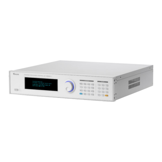
Program and Waveform, etc. 1.3 Specification Chroma 69200-x is the controller without power stage. It is mainly for the user to set the charge/discharge mode and program to control other DC/DC power stage (Regenerative Charge/Discharge Tester). A Controller is able to control 60 channels and receive the charge/discharge test sequences from PC, also to save the test results of Regenerative Charge/Discharge Tester and return to PC. - Page 17 Overview Table 1-1 Front Panel Description Item Symbol Description Main Power Switch: It turns on or off the power. Display It is VFD display configuration to show output settings and measured results. Rotary Knob: The user can turn the “ ”...
-
Page 18: Rear Panel
Charge/Discharge Controller 69200-1 User’s Manual 1.4.2 Rear Panel Figure 1-2 Rear Panel Table 1-2 Rear Panel Description Item Symbol Description Label: The label contains model no. and serial no. ETHERNET Connector: The remote controller uses ETHERNET bus via this connector to connect PC for remote operation. - Page 19 Overview Item Symbol Description AC Power Socket: The AC power cord inputs AC power source by connecting this socket to input stage.
-
Page 21: Installation
Save all packing materials in case the instrument has to be returned. If damage is found, please file a claim with the carrier immediately. Do not return the instrument to Chroma without prior approval. Standard accessories are listed as Table 2-1 shows:... -
Page 22: Requirements For Input Power
Charge/Discharge Controller 69200-1 User’s Manual 2.3 Requirements for Input Power 2.3.1 Ratings Input voltage range : AC INPUT 90-250 V Input frequency : AC INPUT:50/60Hz Maximum input current : 2A Maximum input power : 50VA WARNING It may cause the device to be damaged if exceeding the rated ranged. -
Page 23: Assembling The Racket Kit & Handle
Use a damp cloth with soap and water or a soft detergent to clean the LCD front panel. Please send it back to the distributors or agents of Chroma for internal cleaning. Do not open the chassis cover arbitrarily... -
Page 24: Common Environment Condition
Charge/Discharge Controller 69200-1 User’s Manual 2.8 Common Environment Condition In door use. Altitude up to 2000 meters. Temperature from 0°C to 40°C. Transient over voltage is impulse withstand CAT II. Pollution degree 2. -
Page 25: Local Operation
Installation Local Operation 3.1 Introduction The battery charge/discharge controller can be operated locally or remotely via ETHERNET. The chapter describes the way of inputting test data in local mode using the rotary knob or keyboard on the front panel. If the specified operation mode is not saved before powering off, it will be in local operation mode (system default) when the controller is powered on next time. - Page 26 Charge/Discharge Controller 69200-1 User’s Manual CHARGE Only valid in Press CHARGE screen Test main screen. Press DISCH Only valid in DISCH screen Test main screen. SCAN Press Valid in any SCAN screen Test screen. 69100 Series States: Screen after pressed Yes...
- Page 27 Installation pressed in main CV Discharge screen screen. Press Set in Charge or CP Charge screen Test Discharge. Follow the current situation to charge or discharge when pressed in main CP Discharge screen screen. Press SETUP Valid in any Appear SETUP screen Test screen.
- Page 28 Charge/Discharge Controller 69200-1 User’s Manual Appear CALIB-DC BUS screen Appear CALIB-OUTPUT screen Appear CALIB-DISCHARGE CURRENT screen Appear CALIB-CHARGE CURRENT screen Appear SETUP-OTHER screen Appear Error List screen Press ←↑ Move leftward or Test upward to select parameter for setting →↓...
-
Page 29: Operating Interface & Settings
Installation press for 3 seconds to unlock it. Press SHIFT Press SHIFT for Test 3 seconds to disable REMOTE Press ON/OFF Press this key in Appear OUTPUT screen Test main screen When ON, the LED is on and the screen shows OUTPUT;... -
Page 30: Operating Main Screen
Charge/Discharge Controller 69200-1 User’s Manual Power on screen shows SCAN screen 69100 Series screen Press EXIT to skip to 69206 screen 3.3.2 Operating Main Screen 3.3.2.1 Operating for Charge First use cable to connect the Tester and EUT. Using CC mode as the example for introduction. -
Page 31: Operating For Discharge
Installation Set I (indicates expected output current), VCUT (indicates the cut off voltage to stop this step and skip to next), ICUT (indicates the cut off current to stop this step and skip to next), TIME (indicates the time for count down), V (indicates the voltage of charge state changing from CC to CV), P (indicates the power for changing from CC to CP), S.R. -
Page 32: Operating Of Channel Key
Press EXIT will return to the main screen of original channel. (Default channel) Channel screen description: It can check the settings and test status of other channels controlled by 69200-1. To change the channel for display, simply turn the rotary knob or key in the channel number directly. -
Page 33: Operating Of Scan Key
Installation 3.3.6 Operating of SCAN Key Press SCAN can display the connection status and channel number of 69100/69200. If the system is outputting data, a protection screen will appear. 69100 Series Check IDN: 69200 Series Check IDN: 69200 Series Check Status: 1-60 are displayed in two pages. -
Page 34: Operating Of Setup Key
Based on the selected channel for setting, and each channel is independent. Parameter: Remote: CALIBRATION: Chroma 69200-1 has 4 calibration functions: (1) DC BUS VOLTAGE: It ensures the measurement accuracy of 69206-60-8 input voltage. (2) OUT VOLTAGE: It ensures the measurement accuracy of 69206-60-8 output voltage. -
Page 35: Setting Scpi Communication Method
Installation Press SETUP and select 2. CALIBRATION. Press ENTER to go to 0. CALIBRATION as the figure shown below: Press ENTER and input PASSWORD:6200 as the figure shown below: To quit the CALIBRATION, just press EXIT. It is necessary to enter PASSWORD when running CALIBRATION. The PASSWORD is 6200. - Page 36 Charge/Discharge Controller 69200-1 User’s Manual 3.3.8.1 69200-1 SCPI Commands List Command Description *IDN? Read 69200-1 information. SYST:ERR? Query error. CHANnel[:SOURce] Set active output channel. CHANnel[:SOURce]? Query active control channel. CHANnel:ID? Query the tester to identify. CHANnel:MASTer:ALL? Query the Master Channel ID of tester.
- Page 37 Installation Command Description SOURce:POWer? Query power setting value. Set the cutoff voltage parameters. Unit (V). There are three SOURce:VOLTage:CUTOFF decimal points. Range based on machine specifications. SOURce:VOLTage:CUTOFF? Query cutoff voltage setting value. Set the cutoff current parameters. Unit (A). There are three SOURce:CURRent:CUTOFF decimal points.
- Page 38 Charge/Discharge Controller 69200-1 User’s Manual Command Description BATTery:BCH Set the battery simulator BCH parameters. (float) Unit: %. BATTery:BCH? Query battery simulator BCH setting value. BATTery:BCL Set the battery simulator BCL parameters. (float) Unit: %. BATTery:BCL? Query battery simulator BCL setting value.
- Page 39 Installation Parameter: None Return Value: 1 Command Parameter Description CHANnel:ID? None Query the tester to identify. Syntax: CHANnel:ID? Parameter: None Return Value: It returns 69225-60,000000000000,01.00,1.00 when connected to Tester. It returns NONE when no Tester is connected. Command Parameter Description OUTPut:STATe Output Set output status.
- Page 40 Charge/Discharge Controller 69200-1 User’s Manual Command Parameter Description Float. The minimum resistance value in CR mode. CR low limit value Unit (Ω). Syntax: SPECification:ALL? Parameter: None Return Value: 100.000,10.000,5.000,500.00,1.000,0.010,6000.000,0.150 Command Parameter Description SPEC:VOLT:HIGH? None Query device maximum voltage. Unit (V).
- Page 41 Installation Command Parameter Description Query device maximum resistance value in CR SPEC:CR:HIGH? None mode. Unit (Ω). Syntax: SPEC:CR:HIGH? Parameter: None Return Value: 6000.000 Command Parameter Description Query device minimum resistance value in CR SPEC:CR:LOW? None mode. Unit (Ω). Syntax: SPEC:CR:LOW? Parameter: None Return Value: 0.150 Command...
- Page 42 Charge/Discharge Controller 69200-1 User’s Manual Command Parameter Description Unsigned integer. Set the cutoff time parameters. SOURce:TIME:CUTOFF Cutoff Time Unit (Sec). Range 0 to 65535 Syntax: SOURce:TIME:CUTOFF Parameter: 12 Return Value: None Command Parameter Description SOURce:TIME:CUTOFF? None Unsigned integer. Query cutoff time setting value.
- Page 43 Installation Command Parameter Description SOURce:POW? None Float. Query power setting value. Syntax: SOURce:POW? Parameter: None Return Value: 50.025 Command Parameter Description Float. Set the cutoff voltage parameters. Unit Voltage SOURce:VOLTage:CUTOFF (V). There are three decimal points. Range Cutoff Value based on machine specifications. Syntax: SOURce:VOLTage:CUTOFF Parameter: 20.000 Return Value: None...
- Page 44 Charge/Discharge Controller 69200-1 User’s Manual Command Parameter Description CCV: CV Charge CCP: CP Charge CCD: CC Discharge CVD: CV Discharge CPD: CP Discharge Syntax: SOURce:MODe Parameter: CCC Return Value: None Command Parameter Description SOURce:MODe? None String. Query operation status. Syntax: SOURce:MODe?
- Page 45 Installation Parameter Data Type Description B14 : WIR_LOS B15: AUX_ERR B16: CAL_ERR B17: OUT_UVP B18: SW_OVP B19: SW_UVP B20: BAT_OPP B21: BOH B22: BOL B23: VOH B24: VOL B25: MEM_ERR(for CSU) B26: GRO_ERR(for CSU) B27: D691_ERR_EN(for CSU) B28: TIME_OUT(for CSU) B29: CAN_BUS_ERR(for CSU) B30: 0-Error clear/1-Error set(for CSU) B31: Reserved...
- Page 46 Charge/Discharge Controller 69200-1 User’s Manual Command Parameter Description MEAS:TIME? None Query measurement time. Syntax: MEAS:TIME? Parameter: None Return Value: Parameter Data Type Description Time ID unsigned long Measurement time. Unit (10ms). Command Parameter Description MEAS:ALARM? None Query user alarm status.
- Page 47 Installation Parameter Data Type Description B20: BAT_OPP B21: BOH B22: BOL B23: VOH B24: VOL B25: MEM_ERR(for CSU) B26: GRO_ERR(for CSU) B27: D691_ERR_EN(for CSU) B28: TIME_OUT(for CSU) B29: CAN_BUS_ERR(for CSU) B30: 0-Error clear/1-Error set(for CSU) B31: Reserved Command Parameter Description MEAS:TEMP? None Query measurement temperature.
- Page 48 Charge/Discharge Controller 69200-1 User’s Manual Command Parameter Description MEAS:POW? None Query measurement power. Syntax: MEAS:POW? Parameter: None Return Value: Parameter Data Type Description Measurement power. Unit (W). There are three Meter Power float decimal points. Command Parameter Description MEAS:AH? None Query measurement AH.
- Page 49 Installation Command Parameter Description VH high limit Float. The maximum VH voltage value. Unit (V) VH low limit Float. The minimum VH voltage value. Unit (V). VL high limit Float. The maximum VL voltage value. Unit (V) VL low limit Float.
- Page 50 Charge/Discharge Controller 69200-1 User’s Manual Command Parameter Description VOH Setting (float) Set the battery simulator VOH parameters. Value VOL Setting (float) Set the battery simulator VOL parameters. Value Syntax: BATTery:ALL Parameter: 0,0,0.000,0.000,0.000,0.000,0.000,0.000,0.000,0.000,0.000,0.000,0.000,0.000,0.000,0.000,0 .000,0.000,0.000 Return Value: None Command Parameter Description Query battery simulator all the setting parameter...
- Page 51 Installation Command Parameter Description Set the battery simulator parameter to Ah or SOC. BATTery:PARA Parameter Select 0:Ah 1:SOC Syntax: BATTery:INITial Parameter: 0 Return Value: None Command Parameter Description Query the battery simulator parameter to be Ah or BATTery:PARA? None SOC. Syntax: BATTery:INITial? Parameter: None Return Value: 0...
- Page 52 Charge/Discharge Controller 69200-1 User’s Manual Parameter: None Return Value: 0.000 Command Parameter Description BATTery:OCP Float. Set the Battery Simulator OCP parameters. Syntax: BATTery:OCP Parameter: 0.000 Return Value: None Command Parameter Description BATTery:OCP? None Float. Query Battery Simulator OCP setting value.
- Page 53 Installation Command Parameter Description BATTery:BVH Float. Set the Battery Simulator BVH parameters. Syntax: BATTery:BVH Parameter: 0.000 Return Value: None Command Parameter Description BATTery:BVH? None Float. Query Battery Simulator BVH setting value. Syntax: BATTery:BVH? Parameter: None Return Value: 0.000 Command Parameter Description BATTery:BVL Float.
- Page 54 Charge/Discharge Controller 69200-1 User’s Manual Syntax: BATTery:EFFCHG Parameter: 0.000 Return Value: None Command Parameter Description Float. Query Battery Simulator EFFCHG setting BATTery:EFFCHG? None value. Syntax: BATTery:EFFCHG? Parameter: None Return Value: 0.000 Command Parameter Description Float. Set the Battery Simulator EFFDSG...
- Page 55 Installation Syntax: BATTery:VOH Parameter: 0.000 Return Value: None Command Parameter Description BATTery:VOH? None Float. Query Battery Simulator VOH setting value. Syntax: BATTery:VOH? Parameter: None Return Value: 0.000 Command Parameter Description BATTery:VOLP Float. Set the Battery Simulator VOL parameters. Syntax: BATTery:VOL Parameter: 0.000 Return Value: None Command...
- Page 56 Charge/Discharge Controller 69200-1 User’s Manual Command Parameter Description PROCess:TIME:STATe? None Query the count mode of execution time. Syntax: PROCess:TIME:STATe? Parameter: None Return Value: OFF SYST:ERR? Error Messages 0, (CHAR *)"\"No error\"", //MSG_NO_ERR -101, (CHAR *)"\"Invalid character\"", //MSG_INVALID_CHAR -102, (CHAR *)"\"Syntax error\"", //MSG_SYNTAX_ERR -103, (CHAR *)"\"Invalid separator\"",...
- Page 57 Installation SCPI command settings: 1. CHANnel:SOURce 1 2. OUTPut:STATe OFF 3. SOURce:MODe CCD-------------------------------- 4. SOURce:CURR 1.000-------------------------------- 5. SOURce:VOLTage:CUTOFF 2.500---------------- 6. SOURce:TIME:CUTOFF 0-------------------------- can be replaced with SOUR:ALL 7. SOURce:CURRent:CUTOFF 0---------------------- 8. SOURce:VOLT 2.450--------------------------------- 9. SOURce:POW 4--------------------------------------- 10. SOURce:SLEW 1.00---------------------------------- 11. OUTPut:STATe ON 12.
- Page 58 Charge/Discharge Controller 69200-1 User’s Manual 12. MEAS:OPER?--------------------------------------- 13. MEAS:STATe?--------------------------------------- 14. MEAS:CURR?--------------------------------------- 15. MEAS:VOLT?--------------------------------------- 16. MEAS:POW?---------------------------------------- can be replaced with MEAS:ALL 17. MEAS:TIME?--------------------------------------- 18. MEAS:TEMP?--------------------------------------- 19. MEAS:AH?------------------------------------------ 20. MEAS:KWH?--------------------------------------- 3.3.8.4 CP Discharge Mode Operation Description: When the operating channel is 1 and the current slew rate is set to 1.00A/ms, 4W is fixed for discharging until the voltage is 2.500V.
- Page 59 Local Operation 3.3.8.5 CC Charge Mode Operation Description: When the operating channel is 1 and the current slew rate is set to 1.00A/ms, 1A is fixed for charging until the voltage is 3.80V. Single unit settings: 1.000 (Constant Current must be setup) V C U T 3.80 (Cutoff Voltage must be setup)
- Page 60 Charge/Discharge Controller 69200-1 User’s Manual SCPI command settings: 1. CHANnel:SOURce 1 2. OUTPut:STATe OFF 3. SOURce:MODe CVC-------------------------------- 4. SOURce:CURR 1.000-------------------------------- 5. SOURce:VOLTage:CUTOFF 3.850---------------- 6. SOURce:TIME:CUTOFF 0-------------------------- can be replaced with SOUR:ALL 7. SOURce:CURRent:CUTOFF 0.100---------------- 8. SOURce:VOLT 3.800--------------------------------- 9. SOURce:POW 4--------------------------------------- 10.
- Page 61 Local Operation SCPI command settings: 1. CHANnel:SOURce 1 2. OUTPut:STATe OFF 3. SOURce:MODe CPC--------------------------------- 4. SOURce:CURR 1.000-------------------------------- 5. SOURce:VOLTage:CUTOFF 3.800---------------- 6. SOURce:TIME:CUTOFF 0---------------------------- can be replaced with SOUR:ALL 7. SOURce:CURRent:CUTOFF 0---------------------- 8. SOURce:VOLT 3.850--------------------------------- 9. SOURce:POW 4--------------------------------------- 10. SOURce:SLEW 1.00---------------------------------- 11.
- Page 62 Charge/Discharge Controller 69200-1 User’s Manual ■ VL: Battery Voltage Low for 0% Capacity (it defines the SOC 100% and 0% to get the battery characteristics slew rate). Set the voltage initial capacity via VH~VL judgment. ■ VH: Battery Voltage High for 100% Capacity (it defines the SOC 100% and 0% to get the battery characteristics slew rate).
- Page 63 Local Operation Item Value unit Remarks Total Capacity Forced stop when over SOC_100% Warning when over SOC_0% Warning when under mOhm Fixed value SOC_100% Warning when over SOC_0% Warning when under Forced stop when over Forced stop when over SCPI command settings: (Select initial capacity) 1.
- Page 64 Charge/Discharge Controller 69200-1 User’s Manual Mode B: (1) Battery DCR is fixed to load V-Ah or V-SOC curve. For other DCR curves, a linear constant value has to be input as the figure shown below. Item Value unit Remarks Total Capacity...
- Page 65 Local Operation SCPI command settings: 1. CHANnel:SOURce 1 2. OUTPut:MODe? (Start from step 3 if 0 is returned (Manual Test), or go to step 5 directly.) 3. OUTPut:STATe OFF 4. OUTPut:MODe 1 5. BATTery:OUTPut OFF 6. BATTery:INITial 0-------------------------------------- 7. BATTery:INITial:CAP---------------------------------- 8.
- Page 66 Charge/Discharge Controller 69200-1 User’s Manual Mode B: (2) Load V-Ah and DCR-Ah two related curves. For charge DCR curve, a linear constant value has to be input as the figure shown below. Item Value unit Remarks Total Capacity Forced stop when over...
- Page 67 Local Operation SCPI command settings: 1. CHANnel:SOURce 1 2. OUTPut:MODe? (Start from step 3 if 0 is returned (Manual Test), or go to step 5 directly.) 3. OUTPut:STATe OFF 4. OUTPut:MODe 1 5. BATTery:OUTPut OFF 6. BATTery:INITial 0-------------------------------------- 7. BATTery:INITial:CAP---------------------------------- 8.
- Page 68 Charge/Discharge Controller 69200-1 User’s Manual Mode B: (3) Load V-Ah, Discharge_DCR-Ah and Charge_DCR-Ah three related curves as the figure shown below. Item Value unit Remarks Total Capacity Forced stop when over SOC_100% Warning when over SOC_0% Warning when under SOC_100%...
- Page 69 Local Operation SCPI command settings: 1. CHANnel:SOURce 1 2. OUTPut:MODe? (Start from step 3 if 0 is returned (Manual Test), or go to step 5 directly.) 3. OUTPut:STATe OFF 4. OUTPut:MODe 1 5. BATTery:OUTPut OFF 6. BATTery:INITial 0-------------------------------------- 7. BATTery:INITial:CAP---------------------------------- 8.
-
Page 71: Remote Operation
4.2 Ethernet Remote Control Before using a PC with Ethernet to program the 69200-1 remotely, the address of IP, Gateway and Subnet mask should be learned in advance. A unique IP address has been specified to each device that connected to Ethernet interface. The address allows the system controller to communicate with individual device. -
Page 72: Setting Network Parameter (Ip, Subnet Mask, Gateway)
Charge/Discharge Controller 69200-1 User’s Manual Figure 4-2 4.2.2 Setting Network Parameter (IP, Subnet Mask, Gateway) In general, the PC has no DHCP Server; therefore, this section explains the operation under Private LAN only. All network devices connected require to the IP manually. For example, if the PC uses crossover cable to connect 69200-x, then the IP address of these two devices has to set manually. - Page 73 Remote Operation STEP 1: Click [Control Panel] on the PC and [Network Connection]. Figure 4-3 STEP 2: Select [Local Area Connection] and right-click it to select [Property]. Figure 4-4...
- Page 74 Charge/Discharge Controller 69200-1 User’s Manual STEP 3: Select “Internet Protocol (TCP/IP)” and click Property enter into its setting page. Figure 4-5...
-
Page 75: Ensure Network Connected Successfully
Remote Operation STEP 4: Select “Use the following IP address” (that is to set the IP manually). Here the user has to plan the desired local area network. Figure 4-6 STEP 5: Click OK when the setting is done and it will return to previous level. Click OK to exit and the setting procedure is completed. - Page 76 Charge/Discharge Controller 69200-1 User’s Manual STEP 1: Click [Start] on the desktop of Windows and select [Run]. Figure 4-7 STEP 2: Input “cmd” and click OK to run the cmd program. Figure 4-8...
- Page 77 Remote Operation STEP 3: MS-DOS operating environment is opened by STEP2. Input “ping IP address “directly such as “ping 192.168.1.100”. If there is response, it means the local area network setting is done successfully. Figure 4-9...
-
Page 79: Simple Calibration
When errors are found during usage, the user can perform simple calibration to fix them and notify Chroma for detail and accurate calibration if errors still exist. Following explains some simple ways for the user to identify if the related calibration value is wrong in preliminary. - Page 80 Charge/Discharge Controller 69200-1 User’s Manual please notify Chroma for calibration.
-
Page 81: Theory
Theory 6.1 Overview The 69200-1 is the data collector of 69200 Series, which contains A board (main digital board), K board (KeyPad board), R board (Rotary board) and auxiliary power that can control 69110 Series and 69206-60-8 when connected. Each PCB has specific functions as described below. -
Page 83: Troubleshooting
Troubleshooting Troubleshooting When the POWER S/W is turned on, the VFD PANEL shows nothing the VFD PANEL • is broken or the cable is not connected properly. No action when pressing down the keypad the keypad is broken or the cable is not •... - Page 85 Chroma’s Continuous Quality Process User Manual Customer Feedback Chroma welcomes all comments and recommendations to improve this publication in the future editions. Please scan the QR code below or click the URL http://www.chromaate.com/survey?n=793ce6db-17ef-4cd3-b0de-8bbd09aa38e0 to fill in the customer feedback form. Thank you!
- Page 86 Kuei-shan Hwaya Technology Park Taoyuan County 33383, Taiwan 33383 台灣桃園縣龜山鄉 華亞科技園區華亞一路 66 號 T +886-3-327-9999 F +886-3-327-8898 Mail: info@chromaate.com http://www.chromaate.com Copyright by CHROMA ATE INC. All Rights Reserved. All other trade names referenced are the properties of their respective companies.
Need help?
Do you have a question about the 69200-1 and is the answer not in the manual?
Questions and answers