Table of Contents
Advertisement
Quick Links
Advertisement
Table of Contents

Related Manuals for UFactory LITE 6


Summary of Contents for UFactory LITE 6
- Page 1 V 1.11.0...
-
Page 2: Table Of Contents
Motion Parameters ......................9 Unit Definition ...................10 Additional Information ....................10 Safety Precautions .................17 Lite 6 User Manual-Hardware Section .................17 1. Hardware Installation Manual ...........17 1.1. The Hardware Composition of the robot ..................19 1.2. Robot Installation .............24 1.3. Power Supply for the Robotic Arm ....................27... - Page 3 ................49 1.2 Connect to the Robotic Arm ................55 1.3 UFACTORY Studio Homepage ..................56 1.4 Robotic Arm Setting .......................90 1.5 Live Control ..............99 1.6 Blockly Graphical Programming .....................118 Python IDE .......................120 Recording ......................123 2. Motion Analysis .........123 2.1 Robotic Arm Motion Mode and State Analysis .................128...
- Page 4 ....................161 1.7 Maximum Speed ....................162 1.8 Specifications ....163 Appendix7-Kinematic and Dynamic Parameters of UFACTORY Lite 6...
-
Page 5: Preface
Emergency Stop Button x1 Ethernet Cable x1 Robotic Arm end effector adapter cable x1 Lite 6 Quick Start Guide x1 Main Contents of the Manual Lite6 User Manual Hardware Section (1) Lite6 hardware installation (2) Electrical interface (3) Lite6 end-effector... -
Page 6: Terms And Definitions
(5) After-sales service Terms and Definitions The following terms and definitions apply to this manual. The end effector, installed on the front end of the wrist of the End Effector robotic arm, is used to install special tools (such as grippers, vacuum gripper, etc.), which can directly perform work tasks. - Page 7 The equivalent rotation matrix is: Note: γ corresponds to roll; β corresponds to pitch; α corresponds to yaw. Rx / Ry / Rz representation also, using 3 values to represent the pose (but not three rotation angles), which is the product of a three-dimensional rotation vector [x, y, z] and a rotation angle [phi (scalar)].
- Page 8 axis) Consists of tool center point and coordinate orientation. If the TCP offset is not set, the default tool coordinate system is Tool Coordinate System located at flange center. (Please refer to the For tool coordinate System based motion: The tool center point figure 1) is taken as the zero point, and the trajectory of the robotic arm refers to the tool coordinate system.
-
Page 9: Motion Parameters
Motion Parameters The parameters of the robotic arm are shown in Table 1.1 and Table 1.2. Table 1.1 working range of each joint of the robotic arm Joint Range 1st Axis ±360° 2st Axis ±150° 3st Axis -3.5°~300° 4st Axis ±360°... -
Page 10: Additional Information
UFACTORY devotes to providing reliable and safety information, but these contents do not constitute warranties by UFACTORY. UFACTORY will not have or accept any liability, obligation, or responsibility whatsoever for any... - Page 11 ● Any information given in this manual regarding safety must not be construed as a warranty by UFACTORY that the robot will not cause injury or damage even if all safety instructions are complied with. Safety Alarms in this Manual...
- Page 12 DANGER: This indicates an imminently hazardous electrical situation, which if not avoided, could result in death or serious damage to the device. WARNING: This indicates a potentially hazardous situation which, if not avoided, could result in death or serious damage to the device. HIGH TEMPERATURE This indicates a potential hot surface, which if touched, could result in personal injury.
- Page 13 6. The operator must be trained to guarantee a correct operation procedure when using SDK(Python/ROS/C++) and graphical interface UFACTORY Studio. 7. A complete safety assessment must be recorded each time the robotic arm is re-installed and debugged.
- Page 14 Box). Any modification may lead to unpredictable danger to the integrators. The authorized restructuring needs to be in accordance with the latest version of all relevant service manuals. If the robotic arm is modified or altered in any way, UFACTORY...
- Page 15 (Shenzhen) Technology Co., Ltd. disclaims all liability. 7. Users need to check the collision protection and water-proof measures before any transportation. When the robot cooperates with other machinery, a comprehensive safety assessment of the entire collaboration system should be performed. It is recommended that any equipment that may cause mechanical damage to robot be placed outside the working range during application planning.
- Page 16 fast. 6. Be careful about dropping items that can be caused by accidental power unstable clamping of the robotic arm.
-
Page 17: Lite 6 User Manual-Hardware Section
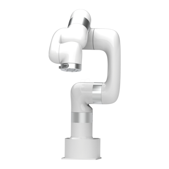
Figure 2-1 Figure 2-2 The Lite 6 robotic arm system consists of a base and rotary joints, and each joint represents a degree of freedom. From the bottom to the top, in order, Joint 1, Joint 2, Joint 3, etc. The last joint is known as the tool side and can be used to connect end-effector (e. - Page 18 After pressing the emergency stop button, the following operations should be performed to re-start the robot: 1. Power up the Lite 6 (Turn the emergency stop button in the direction of the arrow) 2. Enable the Lite 6 (enable the servo motor)
-
Page 19: Robot Installation
Robot] Python-SDK:enable the robotic arm: motion_enable (true) 1.2. Robot Installation 1.2.1. Safety Guidelines for the Robot Environment 1. Make sure the arm is properly and safely installed in place. The mounting surface must be shockproof and sturdy. 2. To install the arm body, check that the bolts are tight. - Page 20 (the end-effector not included in the working range). Working space of Lite 6 (unit: mm) Note:The following working range diagrams are only for safety assessment.
- Page 21 1.2.2.2. Robot Installation The robotic arm has five M5 bolts provided and can be mounted through four ∅5.5 holes in the base of the robotic arm. It is recommended to tighten these bolts with a torque of 20N·m.
- Page 22 Robot Base Mounting (unit: mm) 1.2.2.3. Connect the Power Adapter Plug the connector of the Robotic Arm Power Supply into the interface of the Robotic Arm. The connector is a fool proof design. Please do not unplug and plug it violently. 1.2.2.4.
- Page 23 1.2.2.5. End-effector Installation The End-effector flange has 6 M6 threaded holes and one Ф6 positioning hole, where the end-effector of two different sizes can be mounted. If the effector does not have a positioning hole, the orientation of the end-effector must be documented in a file format, to avoid errors and unexpected results when re-installing the end-effector.
-
Page 24: Power Supply For The Robotic Arm
1.3. Power Supply for the Robotic Arm 1.3.1. Preparation before Power On Ensure the network cable is properly connected. Ensure the Lite 6 will not hit any personnel or equipment within the working range. - Page 25 1.3.2. Power On 1. Release the emergency stop, the power indicator(ROBOT PWR) will on. 2. Use the UFACTORY Studio or SDK commands to complete the operation of enabling the robotic arm. 1.3.3. Shut Down the Robot 1. Press the emergency stop button.
- Page 26 Shutdown. 3.Unplug the socket...
-
Page 27: Electrical Interface
2. Electrical Interface 2.1. Electrical Alarms and Cautions Always follow the warnings and cautions below when designing and installing a robotic arm application. These warnings and cautions are also subject to the implementation of maintenance work. 1. Never connect a safety signal to a non-safety PLC. -
Page 28: End-Effector I/O
IEC standard will cause abnormal behaviour of the robotic arm. Extremely high signal levels or excessive exposure can cause permanent damage to the robotic arm. UFACTORY (Shenzhen) Technology Co., Ltd. is not responsible for any loss caused by EMC problems. - Page 29 female industrial connector. This connector provides power and control signals for the grippers and sensors used on a particular robotic arm tool. Please refer to the figure below: There are 8 pins inside the cable with different colours, each colour represents different functions, please refer to the following table: Pin sequence Color...
- Page 30 Make sure that the connecting tool and the gripper do not cause any danger when the power is cut, such as dropping of the work-piece from the tool. 2.2.1. Digital Output The digital output is implemented in the form of NPN with an open collector (OC).
- Page 31 Note: It is highly recommended to use a protection diode for inductive loads as shown below. 2.2.2. Digital Input The digital input is already equipped with a pull-down resistor. This means that the reading of the floating input is always low. The electrical specifications are as follows: Parameter Typical...
- Page 32 Ω Pull-down Resistors in the 4mA to 20mA Current Range Resolution 1. In the current/voltage mode, the analog input does not provide over-voltage protection. Exceeding the limits in the electrical code may result in permanent damage to the input port. 2.
-
Page 33: Electrical Io
Voltage Mode Current Mode 2.3. Electrical IO This chapter explains how to connect devices to the electrical I/O of the robot. The I/Os are extremely flexible and can be used in many different devices, including pneumatic relays, PLCs, and emergency stop buttons. The figure below shows the electrical interface layout inside the control box. - Page 34 Offline Task Running Robot Enabled Emergency Stop is Pressed It is very important to install the Lite 6 robot according to the electrical specifications. All the I/O must comply with the specifications. The digital I/O can be powered by an internal 24V power supply or by an external power supply by configuring the power junction box.
- Page 35 external power input for I/O. The default configuration is to use internal power, see below. If larger current is needed, connect the external power supply as shown below. The electrical specifications for the internal and external power supplies are as follows. Terminal Parameter Min.
- Page 36 [EIx/SIx/CIx/RI Current(0-0.5) [EIx/SIx/CIx/RI Function Type Note: ** For resistive or inductive loads up to 1H. There is no current protection on the digital output of the Control Box. If the specified values exceeded, permanent damage may result. 2.3.2. Dedicated Safety I/O This section describes the dedicated safety inputs and their configurations of the safety I/O.
- Page 37 2.3.2.1. Default Safety Configuration The robotic arm has been configured by default and can be operated without any additional safety equipment, as the figure below. If there is a problem with the robotic arm, please check the following figure for the correct connection.
- Page 38 2.3.2.4. Automatically Recoverable Protective Stop The door switch is an example of a basic protective stop device. When the door is open, the robotic arm stops. See the figure below. This configuration is only for applications where the operator is unable to close the door from behind.
- Page 39 UFACTORY Studio) How to realize the protection reset function with reset button: 1. Configure "CI0" as the safeguard reset in UFACTORY Studio. The specific steps are as follows: Enter "Settings"-"I/O"-"Input"-Configure CI0 as safeguard reset -"Save". 2. If the robot needs to resume motion, connect SI0 and SI1 to GND, and trigger the motion of the robot by connecting CI0 to GND;...
- Page 40 2.3.3. General Digital I/O Function 2.3.3.1. Configurable Output The digital output is implemented in the form of NPN. When the digital output is enabled, the corresponding connector will be driven to GND. When the digital output is disabled, the corresponding connector will be open (OC/OD).
-
Page 41: Communication Interface
2.3.3.2. Configurable Input The digital input is implemented in the form of a weak pull-up resistor. This means that the reading of the floating input is always high. You must follow the electrical specifications set in the 2.4.1 ‘universal specification’. This example shows how a simple button is connected to a digital input. -
Page 42: Ethernet Tcp/Ip
2.5. Ethernet TCP/IP The robot provides a gigabit Ethernet interface. Ethernet connection steps: • The robot and the computer are connected via Ethernet. One end of the network cable is connected to the network interface of the robot, and the other end is connected to the computer or LAN network interface. If the connection is successful, the network port indicator blinks frequently. - Page 43 192.168.1.*, check if the network proxy is enabled, and check if the robotic arm’s IP address conflicts with that of other devices in the LAN. Please change the computer IP address to the same network segment and close the computer's network proxy. To test whether the computer can communicate with the robotic arm, open the command terminal and input ‘ping 192.168.1.* (the IP address of the robotic arm)’.
-
Page 44: End-Effector
There installation methods mechanical claw of Lite 6: normal installation, the stroke range of the mechanical claw is 0-16mm, and reverse installation, the stroke range of the mechanical claw is 22-38mm. Regardless of the installation method, the stroke of the gripper is only 16mm.The maximum payload of the gripper ≤1kg. - Page 45 Connect the robotic arm and the gripper with the gripper connection cable; Note: 1. When wiring the gripper connection cable, be sure to power off the robotic arm, to set the emergency stop button in the pressed state, and to ensure that power indicator of the robotic arm is off, as to avoid robotic arm failure caused by hot-plugging;...
-
Page 46: Vacuum Gripper
3.2. Vacuum Gripper The vacuum gripper can dynamically suck the smooth plane object with payload ≤1kg. The vacuum gripper is equipped with 1 suction cups, which can be partially selected for use according to the size of the object surface, and the unused suction cup needs to be sealed. Note: If the surface of the object is not smooth, there will be air leakage from the suction cup which makes the object fail to be sucked up firmly. - Page 47 Turn On/Off Vacuum Gripper Example: Blockly: Python-SDK: arm.set_vacuum_gripper(True, wait=False) #Turn on vacuum gripper arm.set_vacuum_gripper(False, wait=False) #Turn off vacuum gripper Note: 1. Python-SDK and UFACTORY Studio provide wrapped functions that can be called to turn on/off the vacuum gripper. UFACTORY Studio-Blockly Command-End Effector-Vacuum Gripper.
-
Page 48: Lite6 User Manual-Software Section
With this application, you can set parameters, move the robotic arm in live control, and create a motion trajectory by simply drag and drop the code blocks of Blockly. UFACTORY Studio allows users to plan the motion trajectory for the robotic arm without programming skills. -
Page 49: Connect To The Robotic Arm
environment have been implemented. 1. The robotic arm is fixed on the plane; protective measures are in place within the range of motion. 2. Check if the connection between the adapter and the robotic arm, power supply, and network cable is stable. 5. - Page 50 (3) PC router connected wireless network, robot and router are connected by Ethernet cable. Note: It is not recommended because of the delay and packet loss of wireless connection. (4) The robot, PC and network switch are connected by Ethernet cable.
- Page 51 1.2.2 IP Configuration Before connecting the robotic arm with UFACTORY Studio (communication with the robotic arm), make sure that the IP address of the computer and the IP address of the control box are on the same network segment. When the control box is shipped from the factory, the default IP address is 192.168.1.xxx (The factory IP address of the device has been marked on...
- Page 52 Step2: Open the “Ethernet” Step3: Open the “Properties” Step4: Open the “IPV4”...
- Page 53 Step5: Then check whether the computer IP is within 192.168.1.2-192.168.1.255 (the tail number should be 2 to 255, and can not be the same as the IP address of the control box). If not, please modify the computer's IP. Step6:...
- Page 54 (1) Open the browser (2) Enter in the search bar: the IP address of the control box: 18333 For example, if the IP address of the control box is 192.168.1.80, enter 192.168.1.80:18333 in the search bar to access UFACTORY Studio.
-
Page 55: Ufactory Studio Homepage
Click the blue【Enable Robot】button to enable it. 【Normal】 indicating that the robotic arm is ready, and【Enable Robot】 becomes 【Robot Enabled】. 1.3.2 5 Main Functional Modules of UFACTORY Studio UFACTORY Studio mainly consists of 5 main functional modules:... -
Page 56: Robotic Arm Setting
Live Control: Gives the ability to control the position of the robot and adjust its posture. Blockly: A graphical programming tool that allows users to achieve programming for the control of the robotic arm, I/O, or end-effector by simply drag and drop the code blocks. Python IDE: Python integrated development environment that uses the Python-SDK API directly and has ability to view the Python code generated by the Blockly project. - Page 57 situation. 1.4.1 Motion Settings 1.4.1.1 Linear Motion Acceleration: The acceleration of linear motion. The larger the value, the less time it takes to reach the set speed. It is recommended to be set within 20 times the maximum speed value for a smooth trajectory.
- Page 58 Joint step: Set the step length for fine adjustment of single joint rotation in Live-control. 1.4.1.3 Sensitivity Setting Collision sensitivity: • When the deviation of the torque detected by the joint exceeds a certain normal range during the movement of the robotic arm, the robotic arm will automatically stop to prevent the robotic arm or the operator from being injured.
- Page 59 motion trajectory. Steps for setting the initial position: 1. Click【Settings】button on the homepage. Enter 【Motion, then click the 【Set】 button next to the Initial Position. 3. Set the initial position of the robot in Live-control. 【OK】: Save the changes. 【Cancel】: Cancel the changes. 1.4.2 End Effector ...
- Page 60 Note: 1. The self-collision prevention model of the gripper can be turned on by clicking the button. 2. When "TCP payload compensation" is turned on, the default TCP payload will be changed to the TCP payload parameter of the gripper. ...
- Page 61 effector. When no end effector is installed at the end of the robotic arm, select [No End Effector] 1.4.3 TCP Settings Set TCP Payload and TCP Offset according to the actual situation. 【TCP Payload】 The load weight refers to the actual mass (end-effector + object) in Kg; ●...
- Page 62 orientation. When the specified value is zero, TCP coincides with the centre point of the tool output flange. 1.4.3.1 TCP Payload On this page, the current payload of the robotic arm can be set and the additional TCP payload data can be recorded. The additional TCP payload data can be referenced during Blockly programming.
- Page 63 default payload, or deleting the payload record. Create New TCP Payload There are two ways to create a new TCP payload: Manual input or Automatic identification. Manually inputting can be selected if the weight of the payload and the approximate center of gravity of the payload are known.
- Page 64 identification is selected. The robotic arm needs to run a series of action commands to calculate the parameters of TCP payload. In addition, it is important to ensure the safety of equipment and personnel near the robotic arm. Note: Once the name of the new payload has been determined, it cannot be changed.
- Page 65 1) Manual Input When the TCP offset parameter of the end effector is known, you can choose to manually input its TCP offset parameter. 2) Identification When the TCP offset parameter of the end effector is unknown,you can choose to identify its TCP offset parameter.
- Page 66 1.4.4 I/O Settings The control box of the robotic arm is equipped with 8 digital input and output signals, which can be set in the Blockly project and SDK only when IO is set to General Input / Output, otherwise the custom setting will not take effect.
- Page 67 【Manual Mode】When set as Manual Mode, the robotic arm can be dragged freely when the input signal remains low level. 【Reduced Mode】The IO is triggered and the robotic arm enters the reduced mode. 【Enable Robot】Enable the robotic arm by triggering IO. 【Save】Save the changes.
- Page 68 Enter emergency stop via CI. Stop button of UFACTORY Studio and Emergency stop code block of Blockly. Emergency stop API of SDK. 【Robot Moving】When the robotic arm is moving, the output is high.
- Page 69 In this interface, the IO input status and IO output status of the control box can be monitored, and the IO output status of the control box can be controlled by clicking the button. 1.4.5 Safety Settings 1.4.5.1 Safety Boundary Safety Boundary When this mode is turned on, the working range of the robotic arm in ●...
- Page 70 1.4.5.2 Reduced Mode Reduced Mode When this mode is turned on, the maximum linear speed, maximum joint ● speed, and joint range of the robotic arm in Cartesian space will be limited.
- Page 71 1.4.6 Mounting Setting the mounting direction of the robotic arm is mainly to inform the control box of the current relationship between the actual mounting direction of the robotic arm and the direction of gravity. If the mounting direction of the robotic arm is set incorrectly, the robotic arm will not be able to accurately recognize the direction of gravity, which will cause the robotic arm to frequently trigger a collision warning and stop motion, and will also result in uncontrolled motion of the robotic...
- Page 72 Indicates that the robotic arm is wall-mounted and the end of the ● robotic arm is facing up. 【WallDown (90 °, 0 °)】 Indicates that the robotic arm is wall-mounted and the end of the ● robotic arm is facing down. 【Customized】...
- Page 73 The method of determining the rotation angle ± direction: Hold it with your right hand and point your thumb in the direction of the robotic arm which is vertically mounted. The direction where your four fingers point is the positive direction and vice versa. The range of rotation angle: ±180°...
- Page 74 In this interface, the user can set the coordinate offset to customize the user coordinate system. X, Y, Z are coordinate values that are offset relative to the base coordinate system. Roll, Pitch, Yaw represents the angular values of orientation relative to the base coordinate system. After this offset setting, user coordinate system becomes the world origin instead of robot base.
- Page 75 When the base coordinate offset parameter is unknown, you can choose to teach USC its base coordinate offset parameter. 【Select】: Select the data to be deleted. 【Set as Default】: Set the offset data as the default offset. 【Default】: The data is the default current base coordinate offset. 【Cancel】: Cancel the selection.
- Page 76 R/P/Y. Generally, it is recommended to use the axis-angle since the axis-angle control is more intuitive. The choice here determines the TCP control mode of the UFACTORY Studio Live Control page. The left side of the figure below is the axis-angle control, the button is displayed as Rx/Ry/Rz;...
- Page 77 【Quick Copy】 After turning on this button, the TCP coordinates and joint angle ● values of the robot can be copied on the real-time control interface. 【Run Package Blockly Project】 Run Package Blockly Project can avoid the Blockly program from being ●...
- Page 78 【Quick access switch】 After enabling quick access, you can quickly adjust parameters through ● the【Quick access button】in any interface of UFACTORY Studio. 【Quick access】 You can select the parameters you want to access quickly, and the ● selected parameters will be displayed on the quick setting interface.
- Page 79 1.4.9.3. Advanced Tools Friction Identification The friction identification is only carried out with the help of technical support, please do not identify by yourself. Advanced Logic...
- Page 80 Clear the IO output when the robot is stopped After turning on 【 Clear IO output when the robot is stopped 】 if the robotic arm receives a stop command, 【 Controller Digital Output 】 or 【 Tool Digital Output 】 will be set to the invalid state. Otherwise, the 【...
- Page 81 Joint Status In this interface, you can get the joint current value and joint voltage value of the robotic arm. The range of the joint voltage value of the robotic arm is: [0, 50V] The range of the joint current value of the robotic arm is: [0, 35A] Note: When using the above functions, the joint firmware version≥...
- Page 82 time, the joint can be dragged by hand to rotate. After confirming the position, please re-lock all the joints manually. Note: 1. Please ensure to hold the robotic arm by hand when unlocking the joint to prevent it from falling down due to the inadequate provision of force, and take measures to protect the surrounding environment and peripheral facilities.
- Page 83 Note: This function should be completed under the guidance of technical support. (Please contact the technical support by the email: support@ufactory.cc) 4. Modbus RTU In the Modbus RTU interface, you can control the gripper and obtain the...
- Page 84 System Settings System Settings mainly include Check Update, System Information, Network Settings, and Log. Check Update Software updates for UFACTORY Studio, and firmware updates for the ● robotic arm. System Information Display the IP address of the connected robotic arm, the firmware ●...
- Page 85 1.4.10.1 System Information On the page of System Information, the robot controller can be rebooted or the joint can be operated, the degree of freedom (number of axis) of the current robotic arm, IP address, firmware version, SN address, and software version of the robotic arm can be checked.
- Page 86 power supply to the robotic arm. 【Shutdown】 Click this button, the page will go back to the【Search the IP Address ● of the Control Box】 page, and the robot controller will shut down. This operation is equivalent to long pressing the Power button of the robot controller, and the shutdown process takes 2 to 3 seconds.
- Page 87 : Click this button to check whether the control box is connected to the Internet. Note: Note: For detailed steps on updating UFACTORY Studio and firmware, please refer to Appendix 4-Lite6 Software/Firmware Update Method. 1.4.10.3 Network Settings The IP address, subnet mask, broadcast address, and default gateway of the robot are displayed on this page.
- Page 88 1. Press the emergency stop button and turn off the power of the control box. 2. Connect RI0 to GND with a cable. 3. Turn on the power of the robot. After hearing the sound of "beep", it means that the IP address of the robot has been reset successfully. The reset IP is 192.168.1.111.
- Page 89 connect the robotic arm. Note: 1. If you do not unplug the cable connecting RI0 and GND, the next time you restart the control box, no matter what IP address you modify, the IP address of the control box will be automatically changed to 192.168.1.111, so after modifying the IP, Be sure to unplug the cable connecting RI0 and GND.
-
Page 90: Live Control
1.5 Live Control 1.5.1 Status Bar The "unconnected robotic arm" indicates that the robotic arm is not connected. Please reconnect the robotic arm on the homepage. If it is not connected, please check if the robotic arm is normally turned on and check if the network connection is normal. - Page 91 Click on the emergency stop button to immediately stop the current motion and clear all cached commands. Note: The “STOP” button in UFACTORY Studio is different from the one on the control box. 1.The “STOP” button in UFACTORY Studio allows the robotic arm to stop the current motion and clear all cache commands immediately.
- Page 92 trajectory, thereby reducing the development workload. When danger occurs, you can also use the manual mode to manually drag the robot away from the danger zone. Drag sensitivity can be set in 【Settings】-【Motion Settings】-【Teach ● sensitivity】. Note: Before opening the manual mode, you must ensure that the mounting method of the robot and the payload setting are consistent with the actual situation, otherwise it will be dangerous.
- Page 93 Press-and-hold【+】or【-】for continuous joint motion in a positive or negative direction, which will stop when the mouse is released. To confirm the direction of joint rotation, please refer the figure below: Lite 6 1.5.6 Linear Motion 1.5.6.1 Introduction Users can control the motion of the robotic arm based on the base coordinate system and TCP coordinate system.
- Page 94 trajectory planning, which needs to be solved by inverse kinematics. Therefore, there may be no solution, multiple solutions, and approximated solutions; and due to the nonlinear relationship between the joint space and Cartesian space, the joint motion may exceed its maximum speed and acceleration limits.
- Page 95 between the angles of β should be inserted, and the angle that formed by the inserted point and A should be smaller than α. The +180° and -180°points of the Roll/Pitch/Yaw are coinciding ● in the space, and the valid range is ±180°, so it is possible to have both ±180°...
- Page 96 Cartesian position. 1.5.7 Operation Mode 1.5.7.1 Lite 6 Operation Interface 【 】 It can switch the control functions between the base coordinate system ● and the tool coordinate system. 【Position/Attitude Real-time Display】 X / Y / Z represents the coordinates of the tool center point (TCP) ●...
- Page 97 in a certain order. 【Real-time Position Control】 X/Y/Z controls the X/Y/Z-axis of the selected coordinate system ● respectively. Click for step motion and long press for continuous motion. 【Real-time Attitude Control】 Roll/Pitch/Yaw controls the Roll/Pitch/Yaw of the selected coordinate ● system respectively.
- Page 98 them for continuous motion. If the end-effector is installed in the robotic arm, make sure to assess whether the robotic arm will hit the obstacles or the fixed surface of the robotic arm when it returns to the zero pose. The robotic arm should be back to the zero pose before packaging.
-
Page 99: Blockly Graphical Programming
arm will slow down or cause an error mechanism. When a command involves displacement and rotation, at the same time, the time required for the displacement motion and the rotational motion depends on the one that takes more time, but in principle, it is better to separate the displacement from the rotation command. - Page 100 write the code manually. 1.6.1 Interface Overview 【 】Click to create a new folder. 【 】Can be converted to Python code and can be used in the Python-SDK library. 【My Project— “xxx”】 Click to expand to display all created items, the currently open item "xxx"...
- Page 101 below). When running the program, you can observe the motion posture of the robotic arm in real time. Note: When the robotic arm is in the simulation mode, you can also run the Blockly motion program to observe the motion of the virtual robotic arm.
- Page 102 【 】Zoom in on the code block. 【 】Zoom out on the code block. 1.6.2.1 The Right Click Mouse Event in the Workspace Right-click on the blank workspace of the non-code block, the function is mainly for all code blocks: 【Undo】: Undo the previous operation.
- Page 103 Right-click in the code block, the function of each module pop up: 【Duplicate】: Copy all code blocks of the current workspace, copy/cut shortcuts with the keyboard and paste them into other files. 【Add Comment】: Users can add a description to the code block, which is identified by the symbol .
- Page 104 sensitivity, load, etc. of the robotic arm. Motion: Common motion commands including linear motion, joint motion, linear motion with arc, sleep time, zero point, and emergency stop. Application: You can import Blockly other projects. GPIO: External input signal triggered event (suitable for plc). End-Effector: Contains common commands to control the end-effector, such as gripper, vacuum gripper.
- Page 105 【Set TCP acceleration()mm/s²】 Set the acceleration of the linear motion in mm/s ● 【Set joint speed()°/s】 Set the speed of joint movement in °/s. ● 【Set joint acceleration()°/s²】 Set the acceleration of joint motion in °/s . The default speed and ●...
- Page 106 1.6.5 Motion 【sleep()s】 After receiving this command, the robotic arm will stop moving for the ● set time, and then continue to execute the following commands. It is mainly used in motion programs that need to do the continuous motion. It is used to buffer more motion commands for successful continuous motion calculation.
- Page 107 Wait(true/false) ,[move] , [edit]】 Set each joint value for the joint movement, with the unit of degree. ● 【move(arc) line X() Y()Z() Roll() Pitch() Yaw() Radius() Wait(true/false) [move] [edit]】 Set the Cartesian coordinate target value of the linear motion and the ●...
- Page 108 1.6.6 GPIO(Control Box and End tool interface) The IO interface is made up of a controller interface and an end tool interface, which can be used to acquire, set, and monitor IO interface operations. The controller has 8 digital input interfaces, 8 digital output interfaces, 2 analog input interfaces, and 2 analog output interfaces.
- Page 109 【 when the analog IO value satisfies the set condition do】 When the monitored analog IO value meets the condition, the commands ● contained in the code block will be executed, and the condition are =, ≠, >, ≥, <, ≤. IO trigger logic of UFACTORY Studio:...
- Page 110 1. UFACTORY Studio obtains the IO state every 100ms, and uses the IO state value obtained for the first time as the initial value. 2. Compare the IO state obtained the second time with the IO state obtained last time. If the IO state changes, a callback meeting the condition is triggered.
- Page 111 successfully; when the vacuum gripper state is 0, it indicates that the object fails to be picked. 【set vacuum gripper (ON/OFF) object detection (true/false)[set]】 Set the vacuum gripper to be on and off. [object detection] = true: detect whether the object is picked, if not, it will jump out of the entire program.
- Page 112 Wait for the next command to be sent, with the unit of seconds. ● 【if (Condition 1) Run (Command 1)】 If Condition 1 is true, then Command 1 will be run. Otherwise, it will ● be skipped. The setting method of the if/else sentence: 1.
- Page 113 1.6.10 Loop 【forever】 The command contained in the loop will be executed in infinite loop. ● 【repeat() times do】 The command contained in the loop will be executed X times. ● 【repeat while/until do】 When the condition is not met, it jumps out of the loop. ●...
- Page 114 1.6.12 Text 【remark】 Remark the code block, which serves as an indicator and can change the ● colour. 【message type】 Types available are: (information/success/warning/error), duration ● indicates the time interval the message is displayed, the unit is in second; the message indicates the content of the prompt message. 【string printing[]】...
- Page 115 1.6.13 Variable 【Create variable】 New variables can be added. After adding a variable, there are three ● commands by default (set the value of the variable, change the value of the variable by adding or subtracting, variable). 【Rename variable】 Rename the variable. ●...
- Page 116 Note: 1. The defined function should be placed in front of the main programs. 1.6.15 Set & Edit Motion Coordinates Long press 【Move】 button to move the robotic arm to the position of the current command. Click 【edit】to pop up the live control interface to re-edit the motion coordinates of the current command.
- Page 117 Click 【Save】to save the changes and close the pop-up window. Click【Cancel】 to cancel the changes and close the pop-up window. Note: In the command, there are sequential points such as A / B / C / D. Etc. If the user clicks 【move】 to skip point B from point A to point C, a safety assessment must be carried out to avoid damage to peripheral facilities Due to the complexity of Cartesian commands, Cartesian spatial trajectory...
-
Page 118: Python Ide
Python IDE Python IDE is a Python development integration environment that can directly use Python-SDK API and check the Blockly projects converted into Python code. 【 】Create a new project. 【 】Create a new file. 【 】Create a new folder. 【... - Page 119 1.7.1 Create a New Project On this page, all current project files are displayed, including Blockly projects converted into Python code. 【 】Import projects. 【 】Export projects. 【 】 Display the current open project and the time it was created. 【...
-
Page 120: Recording
maximum buffer amount (2048), a warning code will be returned. The warning code is decimal 11, and the command will be discarded. The commands issued should not exceed 256 command caches. It is recommended to keep the number of cached/sent commands under 256 all the time. - Page 121 recording time is 5 minutes. The playback will completely repeat the motion trajectory during recording, and the playback speed of the trajectory can be set (x1, x2, x4). A recorded trajectory can be imported into Blockly projects. 【 】Pop-up live control panel. 【...
- Page 122 【 】Download the file. 【 】Delete the file. 【Import Project】Import recorded trajectory. 【Download All】Download all current files.
-
Page 123: Motion Analysis
2. Motion Analysis 2.1 Robotic Arm Motion Mode and State Analysis 2.1.1 The Motion Mode of the Robotic Arm Motions of the robotic arm: joint motion, linear motion, linear circular motion, circular motion, servoj motion and servo_cartesian motion. The following motions are in position mode (Please refer to 【Robot Movement &... - Page 124 needs to enter the servoj mode to use. In servoj mode, the maximum receiving frequency of the control box is 250Hz. If the frequency of sending commands exceeds 250Hz, the redundant commands will be lost. The Python-SDK interface function we provide also reserves the speed, acceleration and time settings, but they will not work at present.
- Page 125 each axis and predicting the motion behaviour of the robotic arm, which is difficult to develop. Operators who design the robotic arm motion path must be qualified with the following conditions: 1. The operator should have a strong sense of security consciousness, sufficient...
- Page 126 and acceleration and map it to the joint space, the servoj mode can replace the planning of the control box, and let robot execute the user's own or third-party (such as ROS Moveit!) planning algorithm. Do not use this mode if users cannot implement trajectory planning and inverse kinematics by themselves.
- Page 127 commands sent will be discarded. ● State 3: Paused state. Pause the currently executing motion and resume the motion at the interruption by setting state 0 again. ● State 4: Stop state. Terminates the current motion and clears the cached subsequent commands.
-
Page 128: Motion Of The Robotic Arm
2.2. Motion of the Robotic Arm 2.2.1. Joint Motion To achieve point-to-point motion in joint space (unit: degree), the speed is not continuous between each command. Blockly example: 【Set joint speed() °/s】: Set the speed of joint movement in °/s. 【Set joint acceleration() °/s²】: Set the acceleration of joint motion in °/s2. - Page 129 The interface set_servo_angle is described in Table 2.1: Table 2.1 Description of set_servo_angle set_servo_angle description set joint angle for joint motion joint ID, 1-7, None or 8 means all joints: a) 1- (Number of axes) Joint number of the robotic arm servo_id E.g.
- Page 130 ex: code = arm.set_servo_angle (servo_id = 1, angle = 1.57, is_radian = True) 2. To wait for the robotic arm to complete the current commands before returning, wait = True; ex: code = arm.set_servo_angle (servo_id = 1, angle = 45, is_radian = False, wait = True) Continuous Joint Motion Inserting an arc transition between two joint motion commands is a way to plan the...
- Page 131 (1) Radius> 0. For example, setting Radius = 60, the turning trajectory is as shown in the arc in the figure below, which can achieve a smooth turning effect. Note: The radius of the arc is smaller than D and D (2) Radius = 0.
- Page 132 2.2.2. Linear Motion and Arc Linear Motion 2.2.2.1. Linear Motion Characteristics of Linear Motion The concept of linear motion Straight linear motion between Cartesian coordinates (unit: mm), the speed is not continuous between each command. Users can control the motion of the robotic arm based on the base coordinate system and TCP coordinate system.
- Page 133 【Set TCP acceleration()mm/s²】: Set the acceleration of the linear motion in mm/s 【move(arc) line X() Y()Z() Roll() Pitch() Yaw() Radius() Wait(true/false) 【move】【edit】】: Indicates the Cartesian coordinate value of the linear motion and the TCP rotation angle in mm and °. Note: Cartesian motion is TCP straight-line motion.
- Page 134 2.2.2.2. Arc Linear Motion Characteristics of Arc Linear Motion: Arc linear motion (Lineb), inserting arc transitions between two straight lines, is a way to plan the continuous movement of the robotic arm. The following figure is a simple example of continuous motion using a circular arc linear motion planning robotic arm.
- Page 135 Note: The radius of the arc is smaller than D and D (5) Radius = 0. There is no arc transition at the turn, it will be a sharp turn with no deceleration, as shown in the figure below. Note: If the motion of the robotic arm is a reciprocating linear motion, you need to set radius=0.
- Page 136 set_position interface: refer to Table 2.2. The set_pause_time interface is described in Table 2.3: Table 2.3 set_pause_time description set_pause_time Description Set the robotic arm pause time sltime pause time, unit: second (s); Parameter wait whether to wait, default is False; 2.2.3.
- Page 137 【move circle position 1 to position 2】: From current position, the whole circle is determined by current position and position1 and positon2, “center angle” specifies how much of the circle to execute. Note: (1) The starting point, pose 1 and pose 2 determine the three reference points of a complete circle.
- Page 138 If the positions of point B and C are swapped, point B is (350, - 50,400,180,0,0), point C is (350,50,400,180,0,0), the robotic arm will draw a circle in a counterclockwise direction. The trajectory of the robotic arm is as follows: set_servo_angle interface: see Table 2.1.
-
Page 139: Singularity
2.3. Singularity 1.Concept Singularities occur when the axes of any two joints of a robotic arm are on the same straight line. At the singularity point, the robot's degrees of freedom will be degraded, which will cause the angular velocity of some joints to be too fast, leading to loss of control. A common situation is that when the wrist joint (the penultimate one) is at or near the axis of the first joint, singularity point will also appear (see Figure 2.1), so the robotic arm should try to avoid... - Page 140 Figure 2.1 singularity 2.Characteristics The characteristic of the singularity is that the planning movement cannot be performed correctly. Coordinate-based planned movements cannot be explicitly translated into joint motions of each axis. When the robot performs motion planning (linear, circular, etc., excluding joint movements) near the singularity point, it will stop to avoid high instantaneous speed of the joint when it passes the singularity point.
-
Page 141: Appendix
Error processing method: Re-power on, the steps are as follows: ● 1. Turn the emergency stop button on the control box 2. Enable the robotic arm UFACTORY Studio enable method: Click the guide button of the error ● pop-up window. Python-SDK enable method: Refer to Error Handling Mode. - Page 142 Software Error Code Error Handling Joint Communication Error Please restart the robot with the Emergency Stop Button on the Control Box. If multiple reboots do not work, please contact technical support. Current Detection Error Please restart the robot with the Emergency Stop Button on the Control Box.
-
Page 143: Control Box Error Code And Error Handling
Joint Negative Overrun Please contact technical support. Joint Commands Error The robot is not enabled, please click Enable Robot. Drive Overloaded Please make sure the payload is within the rated load. Motor Overload Please make sure the payload is within the rated load. Motor Type Error Please restart the robot with the Emergency Stop Button on the Control Box. - Page 144 Please check whether gripper is installed and the baud rate setting is correct. Kinematic Error (xArm 6, xArm 7 or Lite 6)Please re-plan the path. (xArm 5) Please long-press the "Aligning the Hand" or long-press the "Zero Position" button to level the end flange of the robot before moving.(xArm 5) Please long-press the "Aligning the Hand"...
- Page 145 Command Reply Error Please retry, or restart the robot with the Emergency Stop Button on the Control Box. If multiple reboots are not working, please contact technical support. Other Errors Please contact technical support. Feedback Speed Exceeds limit Please contact technical support. Abnormal current in the robotic arm 1.
-
Page 146: Python Sdk Error Code & Error Handling
Robot Base Board Communication Error Please contact technical support. Control Box External 485 Device Communication Error C110 Please contact technical support. Six-axis Force Torque Sensor Mode Setting Error Please make sure that the robotic arm is not in Manual Mode, check C111 whether the given value of this command is 0/1/2 For alarm codes that are not listed in the above table: Power on again. - Page 147 TCP reply length error. Please check the network. TCP reply number error. Please check the network. TCP protocol flag error. Please check the network. The TCP reply command does not match the sending command. Please check the network. Send command error. Please check the network.
-
Page 148: Appendix2-Technical Specifications
Re-enable the robotic arm: motion_enable(true) c. Set the motion state: set_state(0) Appendix2-Technical Specifications Lite 6 Specifications Lite 6 ±440mm ±440mm Cartesian Range -165mm~683.5mm Roll/Yaw/Pitch ± 180° Maximum Joint Speed 180°/s Reach 440mm Repeatability ±0.2mm Max Speed of End-effector 500mm/s *Ambient Temperature Range 0-50 °C*... -
Page 149: Appendix3-The Software/Firmware Update Method
Notes 1) It is recommended to update the firmware and UFACTORY Studio at the same time. 2) After updating, please download the latest "User Manual" and "Developer Manual"... - Page 150 The method for the online update using the xarm-tool-gui tool is as ● follows: 1) Tool download Download address of xarm-tool-gui tool, UFACTORY Studio and xArm Firmware installation package: xArm-Tool-GUI Since your PC connected to the robot can access the Internet, you can directly download the above installation package to your PC.
- Page 151 IP address of the robot, then click "Connect". 3) After successful connection, click the [Check Update] button, then click the [Install Online] in the Firmware installation box (UFACTORY Studio installation box), and finally click the [Install] button in the...
- Page 152 4) After the installation is completed, the console of the xarm-tool-gui will display "Install firmware success" (or "Install Studio success"). And wait for the control box to reboot, the reboot usually takes about 2- 3 minutes. 2. When you use the following network setting methods, please use...
- Page 153 UFACTORY Studio and UFACTORY firmware offline. The control box is directly connected to the PC(The PC is not connected to the Internet) The offline update method using the xarm-tool-gui tool is as follows: ● Tool download...
- Page 154 After successful connection, click the [Install Offline] in the Firmware installation box (UFACTORY Studio installation box), then load the corresponding "firmware" or "UFACTORY Studio" compressed package in the folder. Click the [Install] button. After the installation is completed, the console of the xarm-tool-gui...
- Page 155 3. When you use the following network setting methods, please use UFACTORY Studio to update the UFACTORY Studio and firmware online. ● The method of online update using UFACTORY Studio is as follows: (1)The control box, PC and router are connected by ethernet cable...
- Page 156 (3)PC and router are connected by wireless network, and control box and router are connected by ethernet Cable. Click [Settings] on the UFACTORY Studio homepage, enter [System Settings] → [Check Update], click "Update". Wait for the system to prompt to restart, and then click "Restart", the...
-
Page 157: Appendix4- Maintenance And Inspection
Appendix4- Maintenance and Inspection 1. Long-term placement If the robotic arm is not used for a long time (≥3 months), you need to power on the robotic arm for 6 hours every 3 months to charge the built- in battery of the robotic arm. When powering on the robotic arm, please release the emergency stop button, and the robotic arm does not need to be enabled. -
Page 158: Appendix5- Repair
Appendix5- Repair 1. Repair work must only be done by UFACTORY. After repair work, checks must be done to ensure the required safety level. Checks must adhere to valid national or regional work safety regulations. The correct functioning of all safety functions shall also be tested. - Page 159 (3) UFACTORY will check the product warranty status according to the after-sales policy. (4) Generally, the process takes around 1-2 weeks except for shipment. Note: 1. Please keep the original packaging materials of the product. When you need to send the product back to get repaired, please pack the product with the original box to protect the product during the transportation.
-
Page 160: Appendix6-Product Information
No radioactive materials. 1.3 Transport, Storage and Handling Move the robot to the zero position by UFACTORY Studio, then put the lite 6 robot and Control Box in the original packaging. Transport the robot in the original packaging. -
Page 161: Power Connection
Enabling Device Safeguard Stop by CI of Control Box Performs a Stop Category 2. 1.7 Maximum Speed Mode Typical Scenarios Maximum Speed Teaching mode Live Control Page of UFACTORY Studio 250 mm/s Automatic mode Blockly/ IDE of UFACTORY Studio 500 mm/s... - Page 162 1.8 Specifications Robotic Arm Model LI1000 ±360° ±150° -3.5°~300° Joint Range ±360° ±124° ±360° Payload Maximum Reach 440mm Degrees of Freedom Repeatability ±0.2mm Maximum Joint Speed 90°/s Weight (robotic arm only) Weight (including accessories, packing box) 13KG Footprint 227.6cm Maximum Power 350W Rated Voltage 24VDC...
- Page 163 Appendix7-Kinematic and Dynamic Parameters of UFACTORY Lite 6 Modified D-H Parameters: Size Parameters: (unit:mm) Joint Coordinate Definition Kinematics theta offset (deg) d (mm) alpha (deg) a (mm) Joint1 243.3 Joint2 Joint3 Joint4 227.6 Joint5 Joint6 61.5...
- Page 164 Standard D-H Parameters: Size Parameters: (unit:mm) Joint Coordinate Definition Kinematics theta offset (deg) d (mm) alpha (deg) a (mm) Joint1 243.3 Joint2 Joint3 Joint4 227.6 Joint5 Joint6 61.5...
- Page 165 [179.0, 0.0, 58.4] Link3 0.953 [72.0, -35.7, -1.0] Link4 1.284 [-2.0, -28.5, -81.3] Link5 0.804 [0.0, 10.0, 1.9] Link6 0.13 [0.0, -1.94, -10.2] Manufacturer:UFactory Technology Co.,Ltd Address: 2F, Building M-6, Ma Que Ling Industrial Zone, Nanshan District, Shenzhen, Guangdong, China Website: www.ufactory.cc...
Need help?
Do you have a question about the LITE 6 and is the answer not in the manual?
Questions and answers