Table of Contents
Advertisement
Quick Links
Advertisement
Table of Contents

Related Manuals for Daikin DCM601A71


Summary of Contents for Daikin DCM601A71
- Page 1 Installation Manual intelligent Touch Manager Model DCM601A71 3P291714-2...
- Page 2 Disclosure To the User in USA Part 15 of FCC Note: This equipment has been tested and found to comply with the limits for a Class B digital device, pursuant to part 15 of the FCC Rules. These limits are designed to provide reasonable protection against harmful interference in a residential installation.
- Page 3 WARNING • Only qualified personnel must carry out the installation work. • Consult your Daikin dealer regarding relocation and reinstallation of the con- troller. Improper installation work may result in leakage, electric shocks or fire. • Install the controller in accordance with the instructions in the installation man- ual.
- Page 4 Depending on the radio waves, a distance of 3.5 feet (1 meter) may not be sufficient to eliminate the noise. • If water enters inside of the controller, electric shock may be caused and inner electronics may fail. Installation Manual 3P291714-2 English DCM601A71 intelligent Touch Manager...
-
Page 5: Table Of Contents
2.7.1 Terminals location and conceptual connection diagram ..........23 2.7.2 Requirements that must be met ..................24 Installation ......................25 Wall mounting .......................... 25 3.1.1 Parts to be used ......................25 3.1.2 Installation procedure ....................25 English Installation Manual 3P291714-2 DCM601A71 intelligent Touch Manager... - Page 6 Quick Operation Guide ..................42 Viewing target area and management point information in list format ........42 Viewing target areas and management points ................ 42 Starting/stopping an area or management point ..............43 Installation Manual 3P291714-2 English DCM601A71 intelligent Touch Manager...
-
Page 7: Before Installation
(d-2) Nut (φ4), 4 pcs. (e-1) Cable tie, 1 pc. (e-2) Push mount tie, 3 pcs. (f-1) Installation manual (This manual), 1 pc. (f-2) Manual CD, 1 pc. (f-3) Paper template, 2 pcs. English Installation Manual 3P291714-2 DCM601A71 intelligent Touch Manager... -
Page 8: Understanding External Dimensions
Understanding external dimensions • intelligent Touch Manager body 10-3/32 10-23/32 31/32 31/32 3/16 3/16 3/16 3/16 11-13/32 (in.) • Wall mounting metal plate 9-7/32 2-3/8 1-9/16 (in.) Thickness 1/32 Installation Manual 3P291714-2 English DCM601A71 intelligent Touch Manager... - Page 9 • Frame bracket 11-3/32 9-1/2 2-7/16 9/32 8-27/32 Thickness 1/16 (in.) • Angle bracket 1-1/8 15/32 25/32 1-23/32 Thickness 1/16 (in.) English Installation Manual 3P291714-2 DCM601A71 intelligent Touch Manager...
-
Page 10: Understanding Where Terminals And Switches Are Located
[DIII] The communication line connection terminals for “DIII-NET”, which enables communications with DAIKIN’s air conditioning equipment. [LINE, PHONE] The sockets used when subscribing to the DAIKIN “Air Conditioning Network Service System” online monitoring service for air-conditioning systems. To use the “Air Conditioning Network Service System” service, you need to sign a sepa- rate maintenance contact. -
Page 11: Front Panel
Off: The monitor is powered off. On (Orange): The monitor display is off. On (Green): The monitor display is on. [RESET//] The switch for restarting the intelligent Touch Manager. English Installation Manual 3P291714-2 DCM601A71 intelligent Touch Manager... -
Page 12: Side Face
(example). To secure the wiring with black cable ties, insert the cable tie head into the provided hole. Installation Manual 3P291714-2 English DCM601A71 intelligent Touch Manager... -
Page 13: Determining Installation Place
1-3/16 in. from the right side edge, and 2-3/8 in. from the bottom edge of the unit. <Installation space required for intelligent Touch Manager> Required installa- tion space 1-3/16 3-15/16 3-15/16 1-3/16 9-9/16 MONITOR MONITOR 11-13/32 2-3/8 MONITOR MONITOR 2-3/8 (in.) Wall English Installation Manual 3P291714-2 DCM601A71 intelligent Touch Manager... -
Page 14: Connection
Phillips screwdriver. Connecting DIII-NET-compatible air conditioning equipment DIII-NET is a unique air conditioning equipment communication capability developed by DAIKIN. Using DIII-NET, you can centrally control multiple DAIKIN DIII-NET-compatible air conditioning devices by connecting them to your intelligent Touch Manager. WARNING •... -
Page 15: Terminals Location And Conceptual Connection Diagram
A maximum of 16 indoor units can be connected per remote controller group. A maximum of 64 remote controller groups (128 indoor units) can be connected. A maximum of 64 indoor units can be connected when power distribution is enabled. English Installation Manual 3P291714-2 DCM601A71 intelligent Touch Manager... -
Page 16: Requirements That Must Be Met
Equipment that controls multiple air conditioners is referred to as “centralized controller”. DAIKIN’s product portfolio includes a wide range of centralized controllers suited to differ- ent applications or target sizes, which can be used in combination to construct an optimal air conditioning control system. -
Page 17: Connecting A Lan Cable
WARNING Do not clamp the cables with high-current lines such as a power cable. NOTE For how to connect the intelligent Touch Manager to a PC network, contact your net- work administrator. English Installation Manual 3P291714-2 DCM601A71 intelligent Touch Manager... -
Page 18: Terminals Location And Conceptual Connection Diagram
“FRONT” causes the SERVICE LAN socket to activate (enabled for use). • You cannot close the cover when the switch set to “FRONT”. To close the cover, select “BACK”. SERVICE LAN LAN SW Installation Manual 3P291714-2 English DCM601A71 intelligent Touch Manager... -
Page 19: Connecting I/O Module
Connecting I/O module The intelligent Touch Manager can be used in conjunction with the I/O module. The I/O module provides a maximum of 960 I/O points for controlling non-DAIKIN peripheral equipment such as lighting equipment and security lock systems. WARNING •... -
Page 20: Address Setup
• Power distribution is available for a maximum of 64 air conditioners (indoor units) per DIII-NET port. • With 7 iTM plus adaptors, however, you can connect up to 512 indoor units. Installation Manual 3P291714-2 English DCM601A71 intelligent Touch Manager... -
Page 21: Terminals Location And Conceptual Connection Diagram
• Do not clamp the cables with high-current lines such as a power cable. NOTE When emergency stop input signal is enabled, you cannot restart all the air condition- ers unless you disable it. English Installation Manual 3P291714-2 DCM601A71 intelligent Touch Manager... -
Page 22: Connecting Itm Plus Adaptors
<Terminals location and conceptual connection diagram> intelligent Touch Manager (Rear face) iTM plus adaptor plus ADP IF (intelligent Touch Manager) plus ADP IF (iTM plus adaptor) iTM plus adaptor on which termination resistor must be enabled Installation Manual 3P291714-2 English DCM601A71 intelligent Touch Manager... -
Page 23: Requirements That Must Be Met
<Conceptual drawing of power sup- ply connection> Connect the power supply to the three terminals, L (Live), N (Neutral), and ground in the POWER sec- tion. Earth Earth leakage breaker Power supply 24VAC 60 Hz English Installation Manual 3P291714-2 DCM601A71 intelligent Touch Manager... -
Page 24: Requirements That Must Be Met
• Do not connect the earth wire to gas or water pipes, lighting rod, or telephone earth wire. • Replace the unit when the unit cannot be turned on due to the blowing of the electrical fuse. Installation Manual 3P291714-2 English DCM601A71 intelligent Touch Manager... -
Page 25: Installation
Although you may use any of these screw holes, use ones closer to the edge as much as possible to prevent wobbling. • Secure the wall mounting metal plate at four points using the round-head wood screws. English Installation Manual 3P291714-2 DCM601A71 intelligent Touch Manager... -
Page 26: Flush Wall Mounting
To flush-mount the intelligent Touch Manager to the wall, use the following accessory mounting parts: • Frame bracket, 1 pc. • Angle bracket, 2 pcs. • Flat-head screw (M4×40), 4 pcs. • Pan-head screw (M4×14, with spring washer and plain washer), 4 pcs. Installation Manual 3P291714-2 English DCM601A71 intelligent Touch Manager... -
Page 27: Wall Opening Dimensions
• You need to route in advance the cables connected to the rear face of the intelligent Touch Manager through the cable hole provided at the bottom of the frame bracket. • Before installing the intelligent Touch Manager body, remove the terminal cover from the rear face. English Installation Manual 3P291714-2 DCM601A71 intelligent Touch Manager... - Page 28 You can remove it by hand as this is not screwed. Removing the frame reveals four screw holes, two holes each to the left and right of the monitor display. Installation Manual 3P291714-2 English DCM601A71 intelligent Touch Manager...
- Page 29 <Installing intelligent Touch Manager body> Pan-head screw 4. Snap the resin frame back into the front face of the intelligent Touch Manager as it was before. English Installation Manual 3P291714-2 DCM601A71 intelligent Touch Manager...
-
Page 30: Direct Mounting To Control Enclosure
2. Insert the intelligent Touch Manager into the opening of the control enclosure and install it to the control enclosure using the pan-head screws. 3. Snap the resin frame back into the front face of the intelligent Touch Manager as it was before. Installation Manual 3P291714-2 English DCM601A71 intelligent Touch Manager... - Page 31 To prevent the risk of an electric shock by accidentally touching these power terminals, for safety, be sure to attach the terminal cover before starting the installation procedure. Terminal cover Control enclosure intelligent Touch Manager English Installation Manual 3P291714-2 DCM601A71 intelligent Touch Manager...
-
Page 32: Basic Setup
When finished assigning air conditioner addresses, proceed to the next step. 2. Touch OK. The Language Settings screen appears. CAUTION Before power-on, make sure that all installation and connection procedures are done without problems. Installation Manual 3P291714-2 English DCM601A71 intelligent Touch Manager... -
Page 33: Setting Up Display Language
“Locale setup” allows to set up how you want to see items that are expressed in different ways depending on the region, such as the date/time, temperature, and decimal point, on the display. <Locale Settings screen> English Installation Manual 3P291714-2 DCM601A71 intelligent Touch Manager... -
Page 34: Setting Time Zone
1. On the Time/DST Setup screen, set up the date/time and the daylight saving time schedule. (Enable or disable the daylight saving time function. If enabled, select the start time and the end time.) 2. Touch OK. The A/C Auto Register screen appears. Installation Manual 3P291714-2 English DCM601A71 intelligent Touch Manager... -
Page 35: Confirming Air Conditioner Auto Registration Results
The names of buttons and areas of a wired remote controller used in this section are shown below. <Wired Remote Controller> Address display area Parameter number display area Programming time buttons Temperature setting buttons Timer ON/OFF button Inspection / Test operation button English Installation Manual 3P291714-2 DCM601A71 intelligent Touch Manager... -
Page 36: Procedure For A Wired Remote Controller
2. Using the Temperature Setting buttons, change the value shown in the parameter num- ber display area to “00”. In the address display area, the current address setting is displayed. (This area will show “–” if no address is set.) <Step 2> GROUP SETTING Installation Manual 3P291714-2 English DCM601A71 intelligent Touch Manager... - Page 37 4. Using the Programming time buttons, select the address you want to set. <Step 4> GROUP SETTING 5. Press the Timer ON/OFF button to make the “GROUP” indicator stay lit. The DIII-NET address has been set. <Step 5> GROUP SETTING English Installation Manual 3P291714-2 DCM601A71 intelligent Touch Manager...
-
Page 38: Procedure For A Navigation Remote Controller
F i e l d s e t t i n g l i s t Group No. s e t t i n g Indoor unit Air net No. set Error record Retur n Setting Installation Manual 3P291714-2 English DCM601A71 intelligent Touch Manager... - Page 39 Retur n Change 6. Press the Menu/Enter button. The DIII-NET address has been set. <Step 6> Group No. s e t t i n g (Group) Group No 1-03 Retur n Release English Installation Manual 3P291714-2 DCM601A71 intelligent Touch Manager...
-
Page 40: Setting An Unique Address To Each Unit (When Power Distribution Is Enabled)
Setting an unique address to each unit (when power distribution is enabled) When power distribution is enabled, you need to set a unique address for each unit. For how to set an address, refer to the commissioning manual. Installation Manual 3P291714-2 English DCM601A71 intelligent Touch Manager... -
Page 41: Outdoor Unit Address Setup
1 to 127. The default setting is “0”.) 5. Press the BS3 twice to fix the address setting. 6. Press the BS1 button once to return to the normal mode. English Installation Manual 3P291714-2 DCM601A71 intelligent Touch Manager... -
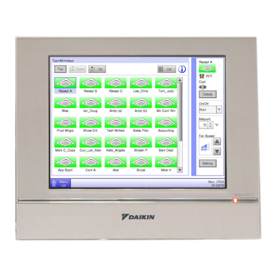
Page 42: Quick Operation Guide
Touch the Down button to go to the area being selected and view the areas and management points in it. Touch the Up button to go to the area one level above the current area. Installation Manual 3P291714-2 English DCM601A71 intelligent Touch Manager... -
Page 43: Starting/Stopping An Area Or Management Point
(operating) and gray when stopped. When Confirmation Dialog is set to “Enabled” in the system setup, the corresponding message appears. Select the Yes button to confirm the Start/Stop operation. English Installation Manual 3P291714-2 DCM601A71 intelligent Touch Manager... - Page 44 3P291714-2 EM11A018 (1203) HT...
Need help?
Do you have a question about the DCM601A71 and is the answer not in the manual?
Questions and answers