Table of Contents
Advertisement
Quick Links
Installation, Operation, and Maintenance
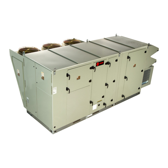
Horizon™ Outdoor Air Unit
Indirect Fired Gas/Electric Heat/Air Source
Heat Pump
Models: OAKD, OAKE/F, OAND, OANE/F
Important:
Proper execution of the tasks outlined in this Installation, Operation, and Maintenance manual require and
assume the technician has been certified as a start up technician for the Horizon Outdoor Air unit. This
includes working knowledge of the Tracer TU program.
Only qualified personnel should install and service the equipment. The installation, starting up, and servicing of
heating, ventilating, and air-conditioning equipment can be hazardous and requires specific knowledge and training.
Improperly installed, adjusted or altered equipment by an unqualified person could result in death or serious injury.
When working on the equipment, observe all precautions in the literature and on the tags, stickers, and labels that are
attached to the equipment.
L'installation et l'entretien de cet équipement doivent être assurés exclusivement par du personnel qualifié.
L'installation, la mise en service et l'entretien d'équipements de chauffage, de ventilation et de climatisation (CVC)
présentent un danger et requièrent des connaissances et une formation spécifiques. Une installation, un réglage ou une
modification inappropriés d'un équipement par une personne non qualifiée peut provoquer des blessures graves, voire
la mort. Lors de toute intervention sur l'équipement, respectez les consignes de sécurité figurant dans la
documentation, ainsi que sur les pictogrammes, autocollants et étiquettes apposés sur l'équipement.
June 2021
SAFETY WARNING
AVERTISSEMENT DE SÉCURITÉ
OAU-SVX01K-EN
Advertisement
Table of Contents
Troubleshooting

Related Manuals for Trane Horizon OAKD


Summary of Contents for Trane Horizon OAKD
- Page 1 Installation, Operation, and Maintenance Horizon™ Outdoor Air Unit Indirect Fired Gas/Electric Heat/Air Source Heat Pump Models: OAKD, OAKE/F, OAND, OANE/F Important: Proper execution of the tasks outlined in this Installation, Operation, and Maintenance manual require and assume the technician has been certified as a start up technician for the Horizon Outdoor Air unit. This includes working knowledge of the Tracer TU program.
- Page 2 CFCs and HCFCs such as saturated or unsaturated HFCs and HCFCs. Important Responsible Refrigerant Practices Trane believes that responsible refrigerant practices are important to the environment, our customers, and the air conditioning industry. All technicians who handle refrigerants must be certified according to local rules. For...
- Page 3 Introduction WARNING AVERTISSEMENT Personal Protective Equipment (PPE) Équipements de protection individuelle Required! (EPI) obligatoires ! Failure to wear proper PPE for the job being undertaken En cas d’équipement de protection individuelle could result in death or serious injury. Technicians, in inadapté...
- Page 4 Never solder, braze or weld on refrigerant lines or any • All Trane personnel must follow the company’s unit components that are above atmospheric pressure Environmental, Health and Safety (EHS) policies or where refrigerant may be present. Always remove...
- Page 5 3. Extinguish any open flame. This document and the information in it are the property of 4. Immediately call your gas supplier. Trane, and may not be used or reproduced in whole or in part without written permission. Trane reserves the right AVERTISSEMENT...
- Page 6 Introduction • Updated the Pre-Startup procedure in the System Configuration and Pre-Start chapter. • Removed the Microchannel (MCHE) Coils section in Maintenance chapter. • Added the Diagnostics values chart table to the Alarms and Troubleshooting chapter. • Added Horizon UC600 attention start up for Service Technician and Startup Forms.
-
Page 7: Table Of Contents
Table of Contents Model Number Descriptions Unit Weight ......25 ... . . 10 Horizon Outdoor Air Unit Rigging . - Page 8 Table of Contents nance ......55 Supply Fan Tracking for Exhaust Fan (Field Enabled) .
- Page 9 ......96 Discharge Air Control ....91 Trane® Horizon™ DOAS ....96 Multi-Zone VAV Control .
-
Page 10: Model Number Descriptions
Model Number Descriptions Horizon Outdoor Air Unit Digit 1, 2 — Unit Type Digit 11 — Evaporator Type Digit 17 — Indoor Fan Wheel OA = Outdoor Air No Cooling DX 4-Row Interlaced 120.6 Digit 3 — Cabinet Size DX 6-Row Interlaced 140.6 Digit 12 —... - Page 11 Digit 25, 26 — Unit Controls No Powered Exhaust 125 MBh 28 kW 2 Row/10 FPI 00 = Non-DDC—Electromechanical Trane—Discharge Air Control AA = 120.6 150 MBh 32 kW 2 Row/12 FPI w/LON Read-Write w/Display 200 MBh 40 kW 2 Row/14 FPI Trane—Space Control w/LON ...
- Page 12 Model Number Descriptions Digit 32 — ERV Size Digit 37 — Air Flow Monitoring No ERV No Airflow Monitoring Airflow Monitoring—IFM 4634 5856 Piezo Ring Airflow Monitoring—PE 6488 6876 Piezo Ring Airflow Monitoring—Outdoor Air 74122 with Display and IFM Digit 33 —...
-
Page 13: General Information
General Information Overview of Manual The Main Unit Display and the RTRM are mounted in the Main Control Panel. The Main Unit Display and RTRM Note: One copy of this document ships inside the control receive information from sensors and customer binary panel of each unit and is customer property. -
Page 14: Space Temperature / Rh Sensor (Optional)
General Information control switches opens, the respective RTRM senses a lack exchanger. The heat exchanger will be constructed of of current while calling for cooling and locks the type 439 stainless steel and be a tubular design capable of compressor out. draining internal condensate. -
Page 15: Hot Water Coils
General Information Hot Water Coils As soon as the unit arrives at the job site: This option consist of a hot water coil located in the Verify that the nameplate data matches the data on primary heat position. Hot water valve is field provided. the sales order and bill of lading (including electrical data). -
Page 16: Unit Clearances
General Information S/A and R/A openings, and flue openings) from the ambient air until the unit is ready for startup. Note: Do not use the unit’s heater for temporary heat without first completing the startup procedure detailed in “Startup,” p. The manufacturer will not assume any responsibility for equipment damage resulting from condensate accumulation on the unit’s electrical and/or mechanical... -
Page 17: Unit Clearances, Curb Dimensions, And Dimensional Data
Unit Clearances, Curb Dimensions, and Dimensional Data OAK Units WARNING Unit Clearances Combustible Materials! Figure 1. Typical installation clearances for OAK unit Failure to maintain proper clearance between the unit heat exchanger, vent surfaces and combustible CLEARANCE FROM materials could cause a fire which could result in death TOP OF UNIT 72"... - Page 18 Unit Clearances, Curb Dimensions, and Dimensional Data Figure 2. Typical installation clearances for OAK unit Figure 4. Typical installation clearances for OAK unit with auxiliary cabinet with auxiliary cabinet CLEARANCE FROM TOP OF UNIT 72" CLEARANCE " CLEARANCE 48" 6'0" 7'0"...
- Page 19 Unit Clearances, Curb Dimensions, and Dimensional Data Dimensional Data Figure 9. Unit dimensional data for OAK 12–30 tons, horizontal supply and vertical/no return (in.) Figure 7. Unit dimensional data for OAK 12–30 tons, vertical supply and vertical/no return without TOP VIEW 106.21 106.45 43.02...
- Page 20 Unit Clearances, Curb Dimensions, and Dimensional Data Figure 10. Unit dimensional data for OAK 12–30 tons, Figure 11. Unit dimensional data for OAK 12–30 tons, horizontal supply and horizontal return with horizontal supply and horizontal return with optional exhaust fan (in.) ERV (in.) TOP VIEW TOP VIEW...
-
Page 21: Oan Units
Unit Clearances, Curb Dimensions, and Dimensional Data OAN Units Figure 13. Typical installation clearances for OAN unit with auxiliary cabinet Unit Clearances Clearance from Figure 12. Typical installation clearances for OANunit top of unit 72” Clearance from top of unit 72” Clearance 48”... - Page 22 Unit Clearances, Curb Dimensions, and Dimensional Data Dimensional Data Figure 15. Typical installation clearances for OAN unit with auxiliary cabinet Figure 18. Unit dimensional data for OAN30–54 tons, vertical supply and vertical/no return without ERV 144.17 6'0" 7'0" 92.07 48.62 Note: Certain options require auxiliary cabinet.
- Page 23 Unit Clearances, Curb Dimensions, and Dimensional Data Figure 20. Unit dimensional data for OAN 30–54 tons, Figure 21. Unit dimensional data for OAN 30–54 tons, horizontal supply and vertical/no return (in.) horizontal supply and horizontal return with optional exhaust fan (in.) TOP VIEW 144.17 TOP VIEW...
- Page 24 Unit Clearances, Curb Dimensions, and Dimensional Data Figure 22. Unit dimensional data for OAN 30–54 tons, horizontal supply and horizontal return with ERV (in.) TOP VIEW 45.87 54.38 144.17 15.10 2.88 SA/RA Duct Flange (Typical) FRONT VIEW 98.80 67.47 95.07 92.07 4.97 31.54...
-
Page 25: Unit Weight And Rigging
Unit Weight and Rigging WARNING WARNING Heavy Objects! Improper Unit Lift! Failure to follow instructions below or properly lift unit Failure to properly lift unit could result in unit dropping could result in unit dropping and possibly crushing and possibly crushing operator/technician which could operator/technician which could result in death or result in death or serious injury, and equipment or serious injury, and equipment or property-only... - Page 26 Unit Weight and Rigging Typical unit weight, center of gravity, and corner weights (percentage of total weight) - air cooled DX units Table 2. with powered exhaust but without ERV Weight (lb) Center-of-gravity (in.) Corner weight (% of total weight) Length Width Corner A...
-
Page 27: Rigging
Unit Weight and Rigging Figure 24. Rigging and center-of-gravity data Figure 23. Cabinet corners 6-point lift, SPREADER BARS horizontal OAK and OAN cabinets (top view) return, no energy wheel Intake hood LIFTING POINTS Condenser section (6 LOCATIONS) DETAIL A LENGTH SCALE 1 : 12 Rigging WIDTH... -
Page 28: Installation
Installation duct work must be installed and connected to top of roof curb before the unit is set on curb. WARNING If a Curb Accessory Kit is not used: Hazardous Service Procedures! 1. Be sure to use flexible duct connections at the unit. Failure to follow all precautions in this manual and on the tags, stickers, and labels could result in death or 2. -
Page 29: General Unit Requirements
Installation Main Electrical Power Requirements Figure 26. Extreme transition in duct work Verify that the power supply complies with the unit nameplate specifications. Inspect all control panel components; tighten any loose connections. Connect properly sized and protected power supply wiring to a field-supplied/-installed disconnect switch and to the main power terminal block (HTB1) in the unit control panel. -
Page 30: Chilled Water Connection Size And Location
Installation Figure 27. Condensate trap installation Table 4. Chilled water pipe chase location (in.) Unit PANEL ENCLOSURE D" NPT FEMALE 63.84 19.50 11.00 5.00 CONNECTOR 93.93 20.64 11.00 5.00 Table 5. Chilled water connection size (MPT-in.) Unit Size MPT-in. OAK 12–30 tons OAN 30–54 tons Filter Installation Each unit ships with 2-inch permanent filters (mist... -
Page 31: Main Unit Power
Installation unit’s supply power wiring is properly sized and installed, Figure 31. OAN utility connections refer to the following guidelines. Figure 29. Main power entrance ELECTRICAL DISCONNECT 11.78 MAIN POWER ENTRANCE FOR UNIT CONDENSATE DRAIN 17.74 1.25 IN. NPT 9.76 104.33 THROUGH THE BASE ELECTRIC... -
Page 32: Standard Wiring
Installation Standard Wiring Verify that the condenser and indoor fans turn freely without rubbing and are properly tightened on the shafts. WARNING Check motor mounting bolts and inlet cone for Proper Field Wiring and Grounding tightness. Free spin wheel by hand to check for proper Required! alignment of motor, wheel, and inlet cone. -
Page 33: Electrical Phasing (Three-Phase Motors)
Installation Proper electrical supply phasing can be quickly Volt 1 + Volt 2 + Volt 3 determined and corrected before starting the unit by using AV (Average Voltage) = an instrument such as an Associated Research Model 45 Phase Sequence Indicator and following these steps: V1, V2, V3 = Line Voltage Readings ... -
Page 34: Main Unit Display And Reliatel Controls
Installation temperature during the “Off” cycle to reduce oil foaming during compressor starts. Oil foaming occurs when AVERTISSEMENT refrigerant condenses in the compressor and mixes with Câblage sur site et mise à la terre the oil. In lower ambient conditions, refrigerant migration corrects nécessaires ! to the compressor could increase. -
Page 35: Controls Using 24 Vac
Installation Controls Using 24 Vac Controls Using DC Analog Input/Output (Standard Low Voltage Multiconductor Wire) WARNING Hazardous Voltage! WARNING Failure to disconnect power before servicing could Hazardous Voltage! result in death or serious injury. Disconnect all electric power, including remote disconnects before servicing. Failure to disconnect power before servicing could Follow proper lockout/tagout procedures to ensure the result in death or serious injury. -
Page 36: Dc Conductors
Installation DC Conductors Table 7. Zone sensor module wiring Distance from Unit to Control Recommended Wire Size 000–150 feet 22 gauge 0–45.7 m 0.33 mm 151–240 feet 20 gauge 46–73.1 m 0.50 mm 241–385 feet 18 gauge 73.5–117.3 m 0.75 mm 386–610 feet 16 gauge 117.7–185.9 m... -
Page 37: Pre-Start Check List
9. Test and Balance recommended prior to Start Up. Notes: • Check list must be completed and returned to Trane before startup is scheduled. ® • Startup must be performed by a Horizon-certified Trane technician with Tracer TU program. -
Page 38: System Configuration And Pre-Start
System Configuration and Pre-Start The following procedure must be completed prior to Important: This section is intended to provide performing the startup procedure in “Startup,” p. 50. This guidelines for navigation through the section describes procedures to navigate the various remote operator display screens. - Page 39 System Configuration and Pre-Start Table 8. Chart of analog and binary input/output (continued) BACnet Point Name Write Default Range Units Description Hardwired input from factory outdoor air flow monitoring AI-10 Outdoor Air Flow Local –– station (AMS). Hardwired input from field installed discharge air Discharge Air AI-11 -40–150...
- Page 40 System Configuration and Pre-Start Table 8. Chart of analog and binary input/output (continued) BACnet Point Name Write Default Range Units Description Speed control for circuit 1 digital scroll or variable Compressor Speed speed AO-03 0–100 Command Circuit 1 compressor. Exhaust Fan Speed AO-04 0–100 Exhaust fan speed output...
- Page 41 System Configuration and Pre-Start Table 8. Chart of analog and binary input/output (continued) BACnet Point Name Write Default Range Units Description AV-16 Occupied Offset ● 0–18 Δ°F Offset used to switch between modes of operation. Supply Fan Speed AV-17 ● 50–100 Setpoint used for constant speed supply fan.
- Page 42 System Configuration and Pre-Start Table 8. Chart of analog and binary input/output (continued) BACnet Point Name Write Default Range Units Description Discharge Air Setpoint used to limit the discharge air Temperature Setpoint AV-43 ● 50°F 40–65 °F temperature reset. Minimum AV-44 Heat Capacity 0–100...
- Page 43 System Configuration and Pre-Start Table 8. Chart of analog and binary input/output (continued) BACnet Point Name Write Default Range Units Description Return Air Enthalpy AV-72 BTU/lb Actively used outdoor air enthalpy. Active Supply Fan Air Flow Actively used setpoint. Controlled by program from Minimum Setpoint AV-74 0–25000...
- Page 44 System Configuration and Pre-Start Table 8. Chart of analog and binary input/output (continued) BACnet Point Name Write Default Range Units Description Auto Reset. Notificaiton when differential presssure switch closes (adj. range) for the filters Energy Recovery Wheel 0=Clean BI-13 before ERV on return air Return Air Filter Status 1=Clogged side.
- Page 45 System Configuration and Pre-Start Table 8. Chart of analog and binary input/output (continued) BACnet Point Name Write Default Range Units Description Enable for electric pre-heat located in front of 0=Off energy BO-13 Pre-Heat Enable 1=On recovery wheel. 0=Off Condenser Fan Start BO-14 Enable for condenser fan(s).
- Page 46 System Configuration and Pre-Start Table 8. Chart of analog and binary input/output (continued) BACnet Point Name Write Default Range Units Description Status indicating when actively bypassing or Energy Recovery Frost 0=Normal BV-41 slowing down energy recovery wheel to prevent Avoidance Status 1=Active frost accumulation.
- Page 47 System Configuration and Pre-Start Table 8. Chart of analog and binary input/output (continued) BACnet Point Name Write Default Range Units Description MV-11 Direct Fired Burner Size – Factory set direct fired burner size. MV-12 Exhaust Fan Wheel Size – Factory set exhaust fan size. 1 = Space Control 2 = Discharge Control 3 = Single Zone VAV 4 = Multi Zone VAV...
-
Page 48: Pre-Start Up
System Configuration and Pre-Start Pre-Start Up Start Up 1. Perform Test and Balance before start up (if possible). 2. Set up Date and Time for unit, helps with diagnosis when looking at alarms and data logs. 3. Check points of interest sheet and confirm in/out of service points. - Page 49 System Configuration and Pre-Start b. Override Circuit 1 to 0%. c. Override HGRH to 100%. d. Maintain head pressure 400 psi. e. Record electrical data, refrigerant pressures, saturated temps and line temps on Horizon. Start Up sheet (available at the end of this document). OAU-SVX01K-EN...
-
Page 50: Startup
Startup Note: Refer to “Startup Form,” p. 96 for a copy of the startup form. AVERTISSEMENT Procédures d’entretien dangereuses ! Indirect Fired Gas Heating • Les techniciens, afin d’être protégés des éventuels Startup risques électriques, mécaniques et chimiques, DOIVENT suivre les précautions contenues dans ce manuel, sur les étiquettes et les autocollants, ainsi WARNING que les instructions suivantes : Sauf indication... -
Page 51: Startup Procedure
Startup operation until source of gas leak is identified and prior to proceeding with the burner corrected. pressure testing. 3. Use only hand force to operate the gas control lever to In the event that the pressure switch fails to operate, the “ON”... - Page 52 For units including an additional separate On-Off shut-off valve. Using unit display (or computer with heater, set heat command output to 49 percent to run Trane Tracer TU), proceed to System Status Display modulating heater startup. When complete with and Override all Compressor stages OFF, Disable...
- Page 53 Startup characteristics can also be caused by flue gas Figure 33. Flame characteristics of properly-adjusted recirculation into combustion air supply. If natural gas systems surrounding buildings or prevailing winds cause recirculation, a flue extension may be required to prevent recirculation. Contact manufacturer prior to making any flue adjustments.
-
Page 54: Safety Controls
Startup Figure 34. OAK/OAN indirect fired gas furnace components Ignition Inducer blower Air-proving switch Controllers Inducer motor Modulating gas valve Condensate drain Rollout (TYP. 2) switch Rollout switch High limit switch Minimum/maximum inlet pressure = 7 IN. WC/14 in. WC (1.7 KPA/3.5 KPA) Flame for natural gas and 10 in. -
Page 55: Maintenance
Maintenance Cooling Season Make sure all personnel are standing clear of the unit before proceeding. The system components will start • Check the unit’s drain pans and condensate piping to when the power is applied. ensure that there are no blockages. Monthly Maintenance •... -
Page 56: Condenser Coil Cleaning
Maintenance Condenser Coil Cleaning WARNING Regular coil maintenance, including annual cleaning, Hazardous Pressures! enhances the unit’s operating efficiency by minimizing: compressor head pressure and amperage draw; Failure to follow safety precautions below could result evaporator water carryover; fan brake horsepower, due to in coil bursting, which could result in death or serious increase static pressure losses;... - Page 57 Maintenance (2) Unit Serial Number: _____________________________________________________ _____________________________________________________ _____________________________________________________ _____________________________________________________ _____________________________________________________ _____________________________________________________ — connection(s) (3) Wiring Diagram Numbers (from unit control panel) _____________________________________________________ — schematic(s) _____________________________________________________ _____________________________________________________ _____________________________________________________ _____________________________________________________ Table 9. Sample maintenance log Refrigerant Circuit #1 Refrigerant Circuit #2 Current Suct.
-
Page 58: Performance Data
Performance Data Table 10. OAKD general data—cooling 12–20 tons high efficiency 12 Tons Downflow 15 Tons Downflow 17 Tons Downflow 20 Tons Downflow OAKD144A OAKD180A OAKD210A OAKD240A Cooling Performance Gross Cooling Capacity, Btu (kW) 147,514 (43.23) 184,392 (54.04) 208,973 (61.24) 245,856 (72.05) Nominal cfm (m 1500–3000 (2549–5097) 1875–3750 (3186–6371) 2125–4250 (3610–7221) 2500–5000 (4248–8495) - Page 59 Performance Data Table 11. OAKD general data—cooling 22–30 tons high efficiency 22 Tons Downflow 25 Tons Downflow 30 Tons Downflow OAKD264A OAKD300A OAKD360A Cooling Performance Gross Cooling Capacity, Btu (kW) 270,442 (79.26) 307,320 (90.07) 368,784 (108.08) 2750–5500 3125–6250 3750–7500 Nominal cfm (m (4692–9345) (5309–10619) (6371–12743)
- Page 60 Performance Data Table 12. OAKE general data—cooling 12–20 tons high efficiency 12 Tons Downflow 15 Tons Downflow 17 Tons Downflow 20 Tons Downflow OAKE144A OAKE180A OAKE210A OAKE240A Cooling Performance Gross Cooling Capacity, Btu (kW) 160,024 (46.90) 189,076 (55.41) 225,948 (66.22) 258,766 (75.84) Heating Performance Gross Heating Capacity, Btu (kW)
- Page 61 Performance Data Table 13. OAKE general data—cooling 22–30 tons high efficiency 22 Tons Downflow 25 Tons Downflow 30 Tons Downflow OAKE264A OAKE300A OAKE360A Cooling Performance Gross Cooling Capacity, Btu 285,822 (83.77) 328,552 (96.29) 360,016 (105.51) (kW) Heating Performance Gross Heating Capacity, Btu 259,134 (75.94) 294,874 (86.42) 321,576 (94.24)
- Page 62 Performance Data Table 13. OAKE general data—cooling 22–30 tons high efficiency (continued) 22 Tons Downflow 25 Tons Downflow 30 Tons Downflow OAKE264A OAKE300A OAKE360A Motor Frame Size, Standard– Varies Varies Varies Oversized Filters Type Furnished Refer to “OAU Filter Guide” Refer to “OAU Filter Guide”...
- Page 63 Performance Data Table 14. OAND general data—cooling 30–40 tons high efficiency (continued) 30 Tons Downflow 35 Tons Downflow 40 Tons Downflow OAND360A OAND420A OAND480A Motor RPM, Standard–Oversized 1750–3500 1750–3500 1750–3500 Motor Frame Size, Standard–Oversized Varies Varies Varies Filters Type Furnished Refer to “OAU Filter Guide”...
- Page 64 Performance Data Table 15. OAND general data—cooling 45–54 tons high efficiency (continued) 45 Tons Downflow 50 Tons Downflow 54 Tons Downflow OAND540A OAND600A OAND648A Motor Frame Size, Standard–Oversized Varies Varies Varies Filters Type Furnished Refer to “OAU Filter Guide” Refer to “OAU Filter Guide”...
- Page 65 Performance Data Table 16. OAKE general data—cooling 12–20 tons high efficiency (continued) 12 Tons Downflow 15 Tons Downflow 17 Tons Downflow 20 Tons Downflow OAKE144A OAKE180A OAKE210A OAKE240A Motor HP (kW), Standard–Oversized 1–5.0 (0.75–3.73) 1–5.0 (0.75–3.76) 1–7.5 (0.75–5.59) 1–7.5 (0.75–5.59) Motor RPM, Standard–Oversized 1750–3500 1750–3500...
- Page 66 Performance Data Table 17. OANE general data—cooling 30–40 tons high efficiency (continued) 30 Tons Downflow 35 Tons Downflow 40 Tons Downflow OANE360A OANE420A OANE480A Diameter Varies Varies Varies Drive Type Direct Drive Direct Drive Direct Drive Number Motors 1 or 2 Motor HP (kW), Standard–Oversized 1.5–15 (1.12–11.19) 1.5–15 (1.12–11.19)
- Page 67 Performance Data Table 18. OANE general data—cooling 45–54 tons high efficiency (continued) 45 Tons Downflow 50 Tons Downflow 54 Tons Downflow OANE540A OANE600A OANE648A Number Used 1 or 2 1 or 2 1 or 2 Diameter Varies Varies Varies Drive Type Direct Drive Direct Drive Direct Drive...
-
Page 68: Superheat And Refrigeration Circuit Data
Performance Data Superheat and Refrigeration Figure 36. Refrigeration diagram: single compressor Circuit Data with reheat Non-Heat Pump Units Figure 35. Refrigeration diagram: single compressor without reheat OAU-SVX01K-EN... - Page 69 Performance Data Figure 37. Refrigeration diagram: dual compressor Figure 38. Refrigeration diagram: dual compressor with without reheat reheat OAU-SVX01K-EN...
- Page 70 Performance Data Figure 39. Refrigeration diagram: triple compressor Figure 40. Refrigeration diagram: triple compressor without reheat with reheat OAU-SVX01K-EN...
- Page 71 Performance Data Figure 41. Refrigeration diagram: quad compressor Figure 42. Refrigeration diagram: quad compressor without reheat with reheat OAU-SVX01K-EN...
-
Page 72: Ashp Units
Performance Data Superheat and Refrigeration Figure 44. Refrigeration diagram: single compressor Circuit Data with reheat ASHP Units Figure 43. Refrigeration diagram: single compressor without reheat OAU-SVX01K-EN... - Page 73 Performance Data Figure 45. Refrigeration diagram: dual compressor Figure 46. Refrigeration diagram: dual compressor with without reheat reheat OAU-SVX01K-EN...
- Page 74 Performance Data Figure 47. Refrigeration diagram: triple compressor Figure 48. Refrigeration diagram: triple compressor without reheat with reheat ‘‘ OAU-SVX01K-EN...
- Page 75 Performance Data Figure 49. Refrigeration diagram: quad compressor Figure 50. Refrigeration diagram: quad compressor without reheat with reheat OAU-SVX01K-EN...
-
Page 76: Alarms And Troubleshooting
Alarms and Troubleshooting Microprocessor Control 3. Utilizing “Method 1” in the RTRM “System Status Checkout Procedure”, check the following: The Main Unit Display and RTRM have the ability to • System status provide the service personnel with some unit diagnostics and system status information. - Page 77 Alarms and Troubleshooting Table 19. Diagnostic values Name Manual or Auto Reset Possible Causes: • VFD not operating OA and/or RA dampers not operating properly Manual Reset. Occurs when the • Indoor Fan Motor Failure supply fan is commanded on but •...
- Page 78 Alarms and Troubleshooting Table 19. Diagnostic values (continued) Name Manual or Auto Reset Possible Causes: • BAS communication down Auto Reset. Occurs when the space • Failed sensor or improper sensor installation Diagnostic: Space Humidity BV-19 humidity active falls outside of •...
- Page 79 Alarms and Troubleshooting Table 19. Diagnostic values (continued) Name Manual or Auto Reset Possible Causes: • Trips after heat command ON and no GV status offer 1 minute • No gas, low gas pressure or high gas pressure to unit •...
-
Page 80: Rtrm Failure Modes
Alarms and Troubleshooting RTRM Failure Modes Variable Speed VFD Troubleshooting Table 20. Status indications WARNING Upper Row Drive Output Live Electrical Components! String Description Stage Failure to follow all electrical safety precautions when The drive is inhibited and cannot be exposed to live electrical components could result in run. -
Page 81: Appendix
Appendix OAU Filter Guide Table 23. OAND units Evaporator Table 21. OADD units Thickness MERV Height Width Evaporator 2 in. 8, 13 Thickness MERV Height Width 4 in. Auxiliary Module (58XX ERV) 2 in. 8, 13 Return Air Thickness MERV Height Width 4 in. -
Page 82: Field Installation Of Factory-Provided Sensors
Appendix Field Installation of Factory- Provided Sensors Figure 51. VELSEN-0021 installation instructions OAU-SVX01K-EN... - Page 83 Appendix Figure 52. BAYSENS036A installation instructions OAU-SVX01K-EN...
- Page 84 Appendix Figure 53. Supply duct static pressure transducer (SDPC) OAU-SVX01K-EN...
- Page 85 Appendix Figure 54. Return duct/space pressure transducer (RDSPC) 1 2 3 OAU-SVX01K-EN...
-
Page 86: Attention Startup Or Service Technician
Attention Startup or Service Technician Horizon UC600 v11.0 Released dehumidification mode the unit will reset the evaporator setpoint by comparing the space conditions to the The programming has gone through an overhaul. Take a setpoints. Previously a fixed setpoint for the evaporator moment to read through the Sequence of Operation temperature was used during dehumidification. -
Page 87: Space Control Or Single Zone Vav And Oa Setpoints
Attention Startup or Service Technician Space Control or Single Zone VAV and OA Expanded Fallback Control Setpoints Where possible, the unit will fall back to other methods of control when it detects a failed sensor. A diagnostic is Space Control or Single Zone VAV will no longer use the displayed for the sensor when another sensor is being outdoor air setpoints if the unit has an ERV, or if the unit used. -
Page 88: Sequence Of Operation
Sequence of Operation Sequence of Operation General Occupied Control Text shown in italics are point names in the programming. Starting Sequence Typically, points ending with “Local” are hardwired Occupied operation begins when the unit is placed in inputs, points ending with “Active” are determined by the Occupied via BAS or when OAUTS-7 &... -
Page 89: Economizer Mode
Sequence of Operation Single Zone VAV Control Multi-Zone VAV Control After completing the starting sequence, the unit adjusts Ventilation Mode locked out. supply fan speed to maintain Space Temperature Active to Space Control Space Temperature Setpoint Active. When the unit is in Dehumidification Mode, the unit adjusts the supply fan Ventilation Mode is enabled when the Outdoor Air speed to maintain the Space Dewpoint to the Space... -
Page 90: Space Control Or Single Zone Vav Control With No Energy Recovery Wheel And 100% Outdoor Air
Sequence of Operation Space Control or Single Zone VAV Control Allowed, Outdoor Air Temperature Active is recorded as Heat Pump Fail Switch Point. Heat pump operation is re- with No Energy Recovery Wheel and 100% attempted when the temperature rises by 5°F. Outdoor Air The unit switches Auxiliary Heating Mode to Allowed Heating Mode is enabled whenever the Outdoor Air... -
Page 91: Air
Sequence of Operation Space Control or Single Zone VAV Setpoint Active, which is written to by Dehumidification Temperature Setpoint (adjustable). Hot Gas Reheat Valve Control, with Energy Recovery Wheel or Command (if installed) is adjusted to maintain Discharge has Mixed Air Air Temperature Setpoint Active. -
Page 92: Supplemental Hot Water Reheat
Sequence of Operation be used to maintain the Discharge Air Temperature operation, the position is modulated to maintain the Setpoint Active. Discharge Air Temperature Setpoint Active for variable effectiveness capacity control. Once the bypass damper Supplemental Hot Water Reheat becomes fully closed, the primary heater will be engaged. If the Hot Gas Reheat Valve Command is at 100%, the hot Energy Wheel Without VFD water valve is energized with Heating Capacity at 0%. -
Page 93: Outdoor Airflow Monitoring
Sequence of Operation Outdoor Airflow Monitoring section the Outdoor Air Damper Position Command will open to the Outdoor Air Damper Maximum Position Units with Outdoor Air Flow Local In Service and Setpoint. Modulating Dampers installed will modulate the Outdoor No Return Air Damper Installed Air Damper Position Command the Outdoor Air Minimum Flow Setpoint. - Page 94 Sequence of Operation Condensate Detection Input will display a fault when the Diagnostic: [High, Low] Discharge Air Temp Lockout is switch located in the condensate pan for the indoor coil displayed when the Discharge Air Temperature Local is has tripped. [above 128°F, below 35°F] for a duration of 10 minutes.
-
Page 95: Sensor Source Failures
Sequence of Operation Sensor Source Failures The following diagnostics are displayed when the respective sensor reading is outside of the expected range, indicating that the sensor may be faulty. Refer to the points list for expected ranges of each input. In some cases, a BAS point is In Service, and will take priority over a hardwired input. -
Page 96: Startup Form
Startup Form ® Trane Horizon™ DOAS Job Name Unit Serial Number Unit Tag Technician Name Horizon Tech Training Completed Date Completed: Startup Date To get a digital copy of this form, please email horizonstartup@kccmfg.com. For further questions please contact the factory at ... -
Page 97: Voltages
Startup Form Verify Indoor Fan Failure Switch (OAB, or OAG Verify Indoor Fan Failure Switch (OAD, OAK or OAN cabinets with UC600 controls) cabinets with UC600 controls and all units without UC600) 1. Note the minimum of Analog Values labelled Supply Fan Air Flow Minimum Setpoint –... -
Page 98: Motor Data
Startup Form Motor Data Rated HP/kW Rated FLA Running FLA Motor Model Number Supply Fan 1 Supply Fan 2 Exhaust Fan 1 Exhaust Fan 2 Condenser Fan 1 Condenser Fan 2 Condenser Fan 3 Condenser Fan 4 Condenser Fan 5 Condenser Fan 6 Compressor Data Model Number... -
Page 99: Refrigeration Startup
Startup Form Refrigeration Startup b. Water Source Heat Pump i. Verify proper water flow through water coil. Test Procedures 7. Adjust charge until subcooling is 10-15. Important: Cooling startup can only be completed if the 8. Record all readings. OA temp is >65°f or <105°F. Heating startup 9. -
Page 100: Indirect Fired Gas Heat Startup
Startup Form Indirect Fired Gas Heat Startup Furnace Data Serial Number Model Number Furnace 1 Furnace 2 Furnace 3 Gas Pressure Settings Measured Pressure Natural Gas Settings Propane Settings Incoming to Unit 7 – 14 11 – 14 in.H2O Between On/Off & Mod. Valve 10.5 in.H2O Stage 1 Manifold (Low Fire) -
Page 101: Programming And Commissioning Program Control Type (Mv-13)
Startup Form Programming and Commissioning Commissioning Do not attempt to perform commissioning by putting points Out of Service and setting a value. The program looks for points that are In Service or Out of Service to Program Control Type (MV-13) change the operation. -
Page 102: Typical Setpoints
Startup Form Typical Setpoints BACnet Point Name Setting Default Range Units Description DISCHARGE AIR CONTROL Outdoor Air Cooling When the Outdoor Air Temperature is above this setpoint, the unit will AV-29 45–100 °F Enable Setpoint be locked into Cooling Mode. When the Outdoor Air Temperature is below this setpoint, the unit will Outdoor Air Heating AV-33... -
Page 103: Final Notes
Startup Form Final Notes Is there something missing or do you have recommendations on improvements? Note here if the outdoor air temperature is too low for cooling testing. Submit completed form to horizonstartup@kccmfg.com Include serial number and job name in subject of email. OAU-SVX01K-EN... - Page 104 For more information, please visit trane.com or tranetechnologies.com. Trane has a policy of continuous product and product data improvement and reserves the right to change design and specifications without notice. We are committed to using environmentally conscious print practices.
Need help?
Do you have a question about the Horizon OAKD and is the answer not in the manual?
Questions and answers