
Related Manuals for SPX RADIODETECTION RD7200


Summary of Contents for SPX RADIODETECTION RD7200
- Page 1 RD7200 ™ Precision utility Cable & Pipe Locator Operation manual 90/RD7200-OM-ENG/06...
-
Page 2: Table Of Contents
Table of Contents Section 1 - Preface ........2 Section 8 - Fault-finding ......31 1.1 Important notices ......... 2 8.1 About fault-finding ........31 1.2 Compliance ..........3 8.2 Preparation ..........31 1.3 Intellectual property ........4 8.3 How to find a fault ........32 Section 2 - Introduction ....... -
Page 3: Section 1 - Preface
Section 1 - Preface Before you begin WARNING! The transmitter is capable of outputting potentially lethal voltages. Take care when applying signals Thank you for your interest in Radiodetection’s to any pipe or cable and be sure to notify other technicians RD7200™... -
Page 4: Compliance
Batteries 1.2 Compliance WARNING! Only use charging equipment provided by The Declaration of conformity is available to download Radiodetection. The use of alternative chargers may cause from the RD7200 cable and pipe product section page a safety hazard and/or reduce the life of the battery. in https://www.radiodetection.com/ CAUTION: Do not let your battery completely discharge For EMC and Safety compliance refer to the relevant... -
Page 5: Intellectual Property
1.3 Intellectual property © 2022 Radiodetection Ltd. All rights reserved. Radiodetection is a subsidiary of SPX Corporation. Radiodetection and RD7200 are registered trademarks of Radiodetection in the United States and/or other countries. Trademarks and Notices. The following are trademarks Radiodetection:... -
Page 6: Section 2 - Introduction
Section 2 - Introduction Users can opt out any time from receiving software and 2.1 About this manual technical notifications or just from receiving marketing material. This manual provides underground utilities survey professionals with comprehensive operating instructions 2.4 Manual outline for the RD7200 locator and transmitter system. -
Page 7: Training
center. More information can be found in the Appendix or from your local Radiodetection representative. It is important to regularly clean and sanitize products which may become contaminated through contact with foul water or other contaminants Headphone use: you need to remain alert to traffic and other hazards that are normally heard outdoors. -
Page 8: Section 3 - System Overview
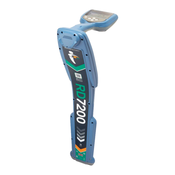
Section 3 - System overview Figure 3.1: RD7200 Locator © 2022 Radiodetection Ltd... -
Page 9: Rd7200 Locator
Locator screen icons 3.1 RD7200 locator 16 Indicates the signal strength and Peak marker Locator features 17 Signal strength: Numerical indication of signal strength Keypad 18 Null / Proportional Guidance arrows: Indicates the LCD with auto backlight location of the line relative to the locator Haptic (vibration) feedback 19 Battery icon: Indicates the battery level Speaker... - Page 10 Figure 3.2 Tx Transmitter © 2022 Radiodetection Ltd...
-
Page 11: Tx-5 And Tx-10 Transmitters
3.2 Tx-5 and Tx-10 transmitters Transmitter features Keypad Removable accessory tray D-cells battery holder Optional Lithium-Ion rechargeable battery pack Figure 3.3 Tx-5 and Tx-10 signal transmitters Transmitter keypad 3.3 Using the menu Power key : Switches the unit on and off. The RD7200 locator and transmitter menus allow you to Opens the transmitter menu select or change system options. - Page 12 Transmitter menu options BATT Set battery type: Alkaline, NiMH or Li- Adjust the speaker volume from 0 ARROW Select NULL or proportional Guidance (mute) to 3 (loudest) (GUIDE) arrows in Peak+ mode FREQ Enable or disable individual frequencies COMPA Enable or disable display of the BOOST Boost transmitter output for a specified Compass feature.
-
Page 13: Section 4 - Operation
Section 4 - Operation 4.1 First use On the transmitter: To fit the D-cell batteries in the transmitter, unlatch the Power options accessory tray. The battery compartment (see figure 3.2) is located underneath the transmitter body. Use the RD7200 systems are shipped as standard configured to turnkey to unlatch the battery compartment. - Page 14 Figure 4.4 Press the retaining latch inwards Figure 4.7 Connecting the Li Ion lead Rotate the battery pack away and up from the latch Repeat on the other side to release the battery pack NOTE: Fully charge your lithium-ion battery pack before completely then lift the battery pack away its first use Transmitter battery pack:...
- Page 15 Charging the battery packs WARNING! Only use charging equipment provided by Radiodetection. The use of alternative chargers may cause a safety hazard and/or reduce the life of the battery. CAUTION: Do not let your battery completely discharge as this may reduce its life or damage it permanently. If you are not using your equipment for a long period do charge them at least once a month.
-
Page 16: Power On / Off
Transmitter Li-ion battery pack Transmitter key actions To recharge the battery pack, remove the pack from the Short press Long press transmitter and connect the transmitter battery charger. Enter the menu Switch power off Scroll through locate frequencies from low to high Take voltage and Take voltage and... - Page 17 Power network frequency Refer to the locator and transmitter menu options (tables 3.1 and 3.2) for more information. Select the correct frequency (50 or 60Hz) for your country or region’s power supply on your locator. NOTE: These procedures refer to both the transmitter and locator unless stated otherwise.
-
Page 18: Dynamic Overload Protection
4.8 TruDepth™ measurement Press the key to accept your selection and return to frequency menu. All RD7200 locators use TruDepth™ to measure depth If you wish to make any further changes follow steps automatically when a good quality reading can be 4 to 6. -
Page 19: Vibration (Haptic) Warnings
4.11 Vibration (haptic) Warnings 4.14 Transmitter power output The RD7200 locators are equipped with a vibration The transmitter supports several power output modes to system in the handle, providing haptic feedback to the help select optimal settings your user when an alarm is active. requirements whilst helping to prolong battery life. -
Page 20: Maximum Voltage
To enable or disable Eco mode 4.17 Measure mode Press the key to enter the menu The transmitter has the capability of providing impedance measurements by determining the resultant Scroll to the BATT menu using the keys impedance across the crocodile clips of the Direct and enter it by pressing the key. -
Page 21: Section 5 - Locating Cables And Pipes
Section 5 - Locating cables and pipes This section introduces the principals and techniques of locating buried cable and pipe utilities with the RD7200 system. For more information on the theory of cable and pipe location, refer to The theory of buried cable and pipe location which is available to download from www.radiodetection.com Switch the transmitter off... -
Page 22: Choice Of Frequency For Active Location
Please note that these signals will also be airborne and This medium frequency is the most useful general- it is advisable to keep the distance between the purpose signal, high enough for induction, outside the transmitter and locator at least 10m / 30’ – this distance power frequency interference band, and with limited coupling to wanted lines however it may not be high may need to be increased, particularly if depth... -
Page 23: Antenna Modes
5.3 Antenna modes Scroll to the ARROW menu using the keys Press the key to enter the ARROW menu The RD7200 system supports up to four antenna modes, exclusively dedicated to locating cable and pipes, and to Select NULL or GUIDE using the keys suit your particular application or the local environment. -
Page 24: Compass
Current • Set the locator sensitivity to approximately 50% by • Depth pressing the To select Guidance mode: NOTE: it may be necessary to adjust the sensitivity level throughout the pinpointing to keep the bar graph on Press the key until the Guidance mode icon scale. -
Page 25: Sweep And Search
requires a transmitter and locator and two people. This 5.7 Sweep and search type of search is referred to as a ‘two person sweep’. Before starting the sweep, define the area of search and There are a number of techniques available for locating the probable direction of lines crossing the area. -
Page 26: Nulling Out
5.8 Nulling Out One person Nulling Out technique: Sometimes it is possible for some utilities to be masked by other utilities and this can happen when one or more utilities are in close proximity to each other or when stronger signals may radiate. In certain applications and congested areas the ‘Nulling’... -
Page 27: Section 6 - Depth And Current Readings
Section 6 - Depth and current readings 6.1 TruDepth™ The RD7200 locator provides automatic depth of buried cables, pipes and sondes and when the locator is correctly orientated above the target line or sonde. Current readings are also displayed simultaneously if the locator is orientated correctly (feature not available in sonde or passive frequency modes). -
Page 28: Current Readings
Method 2 Check that the route of the line is straight for at least • 2 meters (6 ft) to either side of the measurement Apply a signal to a cable or pipe of known depth. point. Locate the cable or pipe; the locator will display •... - Page 29 Applying a transmitter signal The line with the highest current measurement, rather than the line giving the strongest response, is the target The transmitter signal can be connected, clamped or line to which the transmitter signal has been connected. induced to the target line in the same way as the signal Measuring current provides useful information about the for line tracing is applied.
-
Page 30: Section 7 - Locating Techniques
Section 7 - Locating techniques 7.1 Identifying target utilities • Return signal flowing on another line. Use a double- ended connection to by-pass the ground return if possible Induction Choose a signal application point where the line is • If several conductors are running in parallel, and it is not furthest from other lines and not in a congested possible to connect a transmitter, each line may be area... -
Page 31: Signal & Ground Connection
7.2 Signal & ground connection 7.3 Double-ended connections Large diameter water pipes and gas distribution pipes Manhole covers that are laid in sections sometimes have insulated joints between the sections and can be difficult to locate using Sometimes when locating, it is not possible to insert the a single ended connect. -
Page 32: Section 8 - Fault-Finding
Section 8 - Fault-finding Reference readings 8.1 About fault-finding It is good practice to obtain a reference reading from the The RD7200 locator is capable of locating cable to ground stake before you attempt to locate a fault on a ground faults caused by damaged cable sheaths and target line. -
Page 33: How To Find A Fault
NOTE. To establish how often to take readings on the Take readings at the survey intervals determined by the cable or pipe, move away from the ground stake and reference reading. To locate the cable or pipe while take further readings until the arrow has difficulty in using the fault find signal during a Fault-Find survey, locking and the dB reading is low. -
Page 34: Section 9 - Using Accessories
Section 9 - Using accessories 9.1 About accessories • A cable or pipe is accessible at an inspection hole or manhole. Both the transmitter and locator are compatible with a Connecting a clamp wide range of accessories. When an accessory is connected, the locator or Put the clamp connector into the accessory socket transmitter will recognize it and will enable the mode on the front of the RD7200 locator. -
Page 35: Transmitter Clamps
Plug the clamp into the transmitter output socket. Put the clamp around the pipe or cable and ensure that the jaws are closed. Switch the transmitter on. The display will show the Clamp connected icon Figure 9.4 Clamp connected icon The line should be grounded (earthed) on each side of the clamp for the signal to transfer to the line. -
Page 36: Transmitter External Power Supply
The standard and small clamps have a double spring 9.6 Sondes action for positive toroidal contact. Sonde overview WARNING! . The transmitter must only be connected A sonde is a self-contained battery operated transmitter to live services using the appropriate accessory such as a used for tracing the paths of pipes, ducts, sewers and plug connector or live cable connector. - Page 37 inspecting drains. Sondes used in underground drilling and boring operations are normally housed in the boring or drill head behind the boring or drill bit. Locating and tracing a sonde Insert the sonde in the drain or duct access and locate it while it is still just in view at the drain or duct entrance.
-
Page 38: Stethoscopes
How to use a stethoscope locator to behind the sonde ensuring that the locator blade is always in line with the sonde. Find the null Plug the stethoscope into the locator accessory socket. positions A and B (See Figure 8.10). Measure the Press the concave head against each cable in turn to distance between them and multiply by 0.7 to give an detect a maximum signal. - Page 39 can be supplied. The extra length enables the antenna to be carried by a diver on a riverbed or seabed while the locator is used in a surface vessel. It is crucial to have effective communication between the operator with the locator and the diver with the antenna.
-
Page 40: Section 10 - Appendices
Section 10 - Appendices Regularly check your locator for correct operation using 10.1 Care and maintenance eCert (see section 10.6) and the on-board Self-Test. The RD7200 locator and transmitter are robust, durable NOTE: Service by non-approved service centers or and weatherproof. However, you can extend your operators may void the manufacturer’s warranty. -
Page 41: Warranty And Extended Warranty
RD Manager Online is compatible PCs running with a live internet connection. An optional Radiodetection Microsoft Windows 10 64 bit. supplied power source may be required to update your transmitter software. For more information about RD Manager Online refer to the RD Manager Online operation manual. -
Page 42: Tx5 And Tx10 Locator Models, Operation Mode And Active Frequencies
10.7 TX5 and TX10 locator models, operation mode and active frequencies Operation PDLU SLQ H2O+ RD4K Active Mode Frequencies • • • • • • • • • 512Hz CD Clamp • • 570Hz CD Clamp • • • 577Hz CD Clamp •... -
Page 43: Tx 10 Fault Find Locator Models
10.9 TX 10 Fault Find locator models PDLU H2O+ CD pairs • • • • • 8KFF 10.10 List of supported accessories Locator Accessories High Gain Stethoscope 10/RX-STETHOSCOPE-HG Small Stethoscope 10/RX-STETHOSCOPE-S Large Stethoscope 10/RX-STETHOSCOPE-L 640Hz Submersible DD Antenna (10m Cable) 10/RX-SUBANTENNA-640 8kHz Submersible DD Antenna (10m Cable) 10/RX-SUBANTENNA-8K... - Page 44 10/RX-CLAMP-2 2" (50mm) Locator Clamp 10/RX-CLAMP-50 10/RX-CLAMP-4 4" (100mm) Locator Clamp 10/RX-CLAMP-100 10/RX-CLAMP-5 5" (130mm) Locator Clamp 10/RX-CLAMP-130 Locator CD/CM Clamp (only used for Current 10/RX-CD-CLAMP Measurement) Transmitter Accessories 10/TX-LPC-XX Live Plug Connector (XX= EU, UK, US) Live Cable Connector (with Crocodile clips) 10/TX-LCC 10/TX-CLAMP-2 2"...
- Page 45 Earth Lead 10m and Magnet 10/TX-EARTHLEAD-KIT Earth Lead 10m 10/TX-EARTHLEAD Hi-strength Magnet with M4 eyebolt 10/TX-MAGNET Spiral Earth Stake 10/TX-EARTHSTAKE Tx Direct Connection Lead 10/TX-DC-LEAD Tx Direct Connection Lead, crocodile clip 10/TX-DC-LEAD-TEL Tx Direct Connection Lead with banana 10/TX-DC-LEAD-BAN connectors, insulated plug/socket Tx Direct Connection Lead with banana 10/TX-DC-LEAD-OPEN connectors, Open Grid Europe...
- Page 46 Super Sonde 33kHz, depth up to 15m 10/SONDE-SUPER-33 4.5" (115mm) Diameter Floats/Pair for Sewer and Super 10/SONDE-FLOATS Sondes S6 Microsonde Kit, incl. battery and case 10/SONDE-MICRO-33 Pack of 10 × Batteries for S6 Microsonde 10/SONDE-MICRO-BATPACK 10/SONDE-MINI-33 S9 MiniSonde, incl. battery and case Pack of 10 ×...
- Page 47 Bendi Sonde with M10 Male End Cap (512Hz continuous) 10/SONDE-BENDI-512 Pack of 5 AA Batteries 10/SONDE-BENDI-BATPACK 10/TRACE50-XX FlexiTrace 50m (Tx powered pushrod transmitter) (XX = D, F, GB, NL) 10/TRACE80-XX FlexiTrace 80m (Tx powered pushrod transmitter) (XX = D, F, GB, NL) 4.5mm 50m Flexrod 10/FLEXRODF50-4.5 4.5mm 80m Flexrod...
- Page 48 Locator power accessories and spares Li-Ion rechargeable battery pack with mains charger 10/RX-MBATPACK-LION-K-XX (includes power lead) (1) Li-Ion rechargeable battery pack with auto charger (1) 10/RX-ABATPACK-LION-K Li-Ion rechargeable battery pack with mains and 10/RX-MABATPACK-LION-K-XX automotive charger (includes power lead) (1) 2 cells battery tray (2x D Cell / LR20) (2) 10/RX-2DCELL-TRAY (1) Compatible with RD7200/RD8200, RD8100/RD8100 and Marker (MRX) Locators...
- Page 49 Li-Ion rechargeable battery pack (no charger) (1) 10/TX-BATPACK-LION 8 cells battery tray (8x D Cell / LR20) 10/TX-8DCELL-TRAY (1) Li-Ion rechargeable packs cannot be charged in the transmitter Replace XX with AU, EU, UK or US Mains Leads C7 Mains lead, 6.5' (2m), 2.5A 10/MAINS-LEAD-C7-XX C13 Mains lead, 6.5' (2m), 2.5A 10/MAINS-LEAD-C13-XX...
- Page 50 Transport and Storage Accessories Locator backpack and bag for Tx transmitter (without 10/LOCATOR-BACKPACK-SET tool tray) - set of soft carry bags Locator backpack 10/LOCATOR-BACKPACK Tx transmitter (without tool tray) soft carry bag 10/TX-BAG Locator and Tx transmitter soft carry bag 10/LOCATORBAG Locator and Tx transmitter hard case 10/RD7K8KCASE-USA...
- Page 51 Copyright © 2022 Radiodetection Ltd. All rights reserved. Radiodetection is a subsidiary of SPX Corporation. RD7200, Power Filters,Peak+, eCert, StrikeAlert, SideStepAuto, CALSafe, RD Manager Online and Radiodetection are either trademarks of Radiodetection in the United States and/ or other countries. Microsoft and Windows are either registered trademarks or trademarks of Microsoft Corporation in the United States and/or other countries.
Need help?
Do you have a question about the RADIODETECTION RD7200 and is the answer not in the manual?
Questions and answers