
Related Manuals for FoxESS A7300P1-E1-R


Summary of Contents for FoxESS A7300P1-E1-R
- Page 1 User Manual FoxESS EV Charger Please read the product manual prior to installation to prevent improper operation.
-
Page 2: Table Of Contents
Table of Contents 1. Notes on This Manual ....................1 1.1 Scope of Validity ....................1 1.2 Target Group .....................1 1.3 Symbols Used ....................1 2. Safety ......................... 2 3. Packing List ........................3 4. Introduction ........................ 4 5. Technical Data ......................5 6. -
Page 3: Notes On This Manual
1. Notes on This Manual 1.1 Scope of Validity This manual describes the assembly, installation, commissioning, maintenance and troubleshooting of the following model(s) of Fox products: A7300P1-E1-R A7300P1-E1-B A7300P1-E1-S A7300P1-E2-R A7300P1-E2-B A7300P1-E2-S A7300S1-E1-R A7300S1-E1-B A7300S1-E1-S A7300S1-E2-R A7300S1-E2-B A7300S1-E2-S Note: Please keep this manual where it will be accessible at all times. -
Page 4: Safety
Do not use the equipment if any operating anomalies are found. Avoid temporary repairs. All repairs should be carried out using only approved spare parts, which must be installed in accordance with their intended use and by a licensed contractor or authorized FoxESS service partner. -
Page 5: Packing List
3. Packing List Object Name Charger Mounting backplane Mounting bracket RFID card Expansion Tube Expansion Screw Tubular terminal Screw assembly Self tapping screw... -
Page 6: Introduction
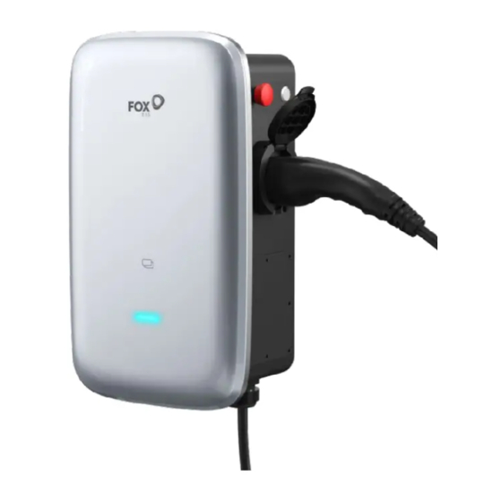
4. Introduction Stop switch in Plug and Charge mode Credit card area Status indicator light Side cover Charging plug Plug version Stop switch in Plug and Charge mode Credit card area Side Status indicator light cover Charging socket Socket version... -
Page 7: Technical Data
5. Technical Data Model A7300 General Name AC Charger Input Input line 1P+N+PE Rated voltage 230Vac,±20% Rated current 50/60Hz Rated frequency Output Output voltage 230Vac,±20% Maximum output current Rated power 7.3kW Interaction method Charging connection method With cable/socket Card reader Mifare ISO/IEC 14443 A Start-up mode Plug and Charge/RFID Card/APP... -
Page 8: Installation
6. Installation 6.1 Product Handling To ensure safety, the following points should be paid attention to: All accessories are placed separately during transport or handling. Avoid violent shock and impact, and take it lightly. Avoid inversion. 6.2 Out of the box inspection Open the charging pile packaging, please check the random attachment according to the attachment list. - Page 9 • Wall-mounted installation method: 1. Open the package and mark 4 holes in the wall (φ 8 * 50mm). 2. Fit into the expansion tube. 3. Attach the mounting backplane with screws to the mounting wall. 4. Attach the bracket to the charger. 5.
- Page 10 • Floor type / Vertical installation method: 1. Drill holes on the cement floor,four 165 * 95 holes with diameter φ 10mm deep 50mm screws and one φ 60mm through duct hole. 2. Install and fix the anchor screws. 3. The input line runs through the column hole through the bottom of the column. 4.
-
Page 11: App Download
Electrical Connection The leakage protection switch needs to be installed.The leakage protection switch shall use TypeA, not less than 63A. And the input wire leads out from the leakage protection switch, choose7~9 AWG wire. Step 1: Peel three L, N and PE copper 16mm with wire stripping pliers, and press L, N, PE and tube terminals with terminal pliers. -
Page 12: Operation
8. Operation 8.1 Charger Status Indicators LED Indicator description Definition Green Flashing Device available Blue Steady EV connected,User not authorized Blue Flashing Authorized, Wait for charging Blue marquee light Charging Blue Flashing Charging suspension Green Steady Charging Finish, Wait for unplug Yellow Steady Charging Locking Red Steady... -
Page 13: Charging Mode And Operation
8.2 Charging mode and Operation Users can set three charging modes through the charging mode setting interface of the APP: controlled, locked, plug and charge. Plug and charge mode Charging will start automatically after EV plugged in. If you want to stop the charging, just press the stop button on the side of the charger. - Page 14 • Stop Charging: 1. Swipe card 2. Charging session end The controlled mode with APP • Start Charging: 1. Set the charger to the Controlled mode 2. Insert the charging plug into the EV 3. Click to Start the Charge on the APP 4.
-
Page 15: Maintenance
9. Maintenance Troubleshoot by Alarm information on APP or LCD display If fault occurs, users can check the fault information on the APP or by blinks of the LED indicator light. Fault code on app Solution Set the electronic lock status to the correct position. -
Page 16: Decommissioning
10. Decommissioning 10.1 Dismantling the charger - Disconnect the charger from AC Input and AC output. - Disconnect communication and optional connection wirings. Remove the charger from the bracket. - Remove the bracket if necessary. 10.2 Packaging If possible, please pack the charger with the original packaging. If it is no longer available, you can also use an equivalent box that meets the following requirements. - Page 17 The copyright of this manual belongs to FOXESS CO., LTD. Any corporation or individual should not plagiarize, partially or fully copy (including software, etc.), and no reproduction or distribution of it in any form or by any means is permitted. All rights reserved.
Need help?
Do you have a question about the A7300P1-E1-R and is the answer not in the manual?
Questions and answers