Advertisement
Quick Links
4.3 Electrical Connections ATTENTION
Electrical work to be carried out by competent qualified and licensed electricians
in strict conformity to ruling national conditions and local regulations. All wiring
and external switchgear to comply with the ruling local regulations in
accordance with the latest edition of IEE wiring regulations.
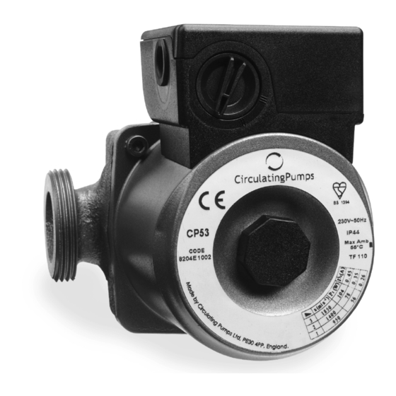
Observe pump name plate data.
For pump fuse protection use a 3 Amp fuse.
A means of disconnection from the power supply having a contact separation of
at least 3mm in all poles must be provided.
If the pump already has a cable fitted to it, ensure the pump is isolated from the
mains before removing the terminal cover.
Wiring Procedure
1. Use heat resisting 3 x 0.75mm
2
core cable with rubber insulation rated at
110ºC minimum.
2. Cut cable to required length.
3. Remove terminal cover.
4. Thread cable through grommet.
5. Depress levers to open cable clamps. Connect cable - Brown to L,
Blue to N, Yellow/Green to
see Fig 6.
6. Adjust cable position and press outer sheath into clamp. See Fig 6.
7. Refit terminal cover, locating cover onto motor and tighten screws.
The cable must not come in contact with the pump body or pipework.
WARNING - 'THIS PUMP MUST BE EARTHED'
Fig 6 Plan view of
Terminal Arrangement
L
5. Commissioning/Operation ATTENTION
Open both valves either side of the pump.
In normal operation the pump surface can be hot (up to 125ºC) creating a risk
of being burnt.
Manual Restart (First Commissioning)
During this operation be aware of the risk of scalding
from escaping hot water or steam.
Before switching the pump on the manual restart Fig 7 should be unscrewed and
withdrawn to engage in the motor shaft. Check that the shaft rotates freely, and
that the knob can be seen rotating on initial start up of the circulator. Screw
manual restart back in.
Fig 7 Manual Restart Knob and Speed Regulator Knob Location
(CP23/CP43/CP53/CP63 only).
Venting
When the system is filled with water the pump
will normally self vent air within a short while
of switching on.
In cases where the pump venting is slow (identified
by pump noise) the pump bearings may be quickly
vented by using the manual restart knob.
During this operation be aware of the risk of
scalding from escaping hot water or steam.
During this operation ensure the pump is switched off.
Once the system has filled, switch off the pump, unscrew the manual restart knob
applying sideways pressure to the screw until water emerges from it. Screw the
manual restart knob back in. Switch pump back on.
Note, a system may take 24 hours to vent all the air in the system to atmosphere.
ATTENTION DO NOT run the pump dry as this will result in bearing failure.
Speed Regulator
Output of the CP range of domestic circulators is by 3 speed control. (Single speed
versions are also available)
Speed regulator adjustment should only be made with electrical supply
switched off.
1. It is always preferable to use the lowest performance where this gives circulation
sufficient to heat all the heat emitters evenly (uneven distribution of heat may
be due to the need to balance the flow of water in each heat emitter).
2. If the pump performance requirement is not known start with the lowest pump
setting. If heat emitters remain cold, or if the boiler inlet and outlet temperature
differential (specified by the manufacturers of the boiler) is not achieved increase
the flow by adjusting the speed control as shown in fig.7.
ATTENTION too high a speed setting may result in pumping over or
drawing in air.
Important - DO NOT use pump isolating valves for performance control.
No routine maintenance is necessary, however, during prolonged shutdown e.g.
summer months, it is advisable to run the pump for a few minutes every few weeks.
Locked Pump
Should the pump fail to start, switch to maximum setting. If the pump still does not
start, the manual restart knob can be used to free a locked pump (see manual restart
procedure - section 5). Once the pump is running the regulator should be reset to
its original position.
Faults and Remedies
Pump Fails to Start
Check power supply fuses.
Check voltage at pump terminals (see pump nameplate data).
N
Check electrical connection wiring procedure (see section 4.3).
Check rotor free to rotate (see section 6).
Pump Starts but Provides Incorrect Circulation
Check pump valves open.
Check pump case and system adequately vented (see section 5).
Check correct electrical regulator setting (see section 5).
Noise
Check electrical regulator setting and readjust as required (see section 5).
Noise due to cavitation can be subdued by increasing the system pressure within
the permissible limits.
Pump may require 48 hours to attain normal quiet operation.
Spare Parts
No non-approved replacement parts may be used.
Speed Control
CALOR SRL
Str. Progresului nr. 30-40, sector 5, Bucuresti
Manual Restart Knob
tel: 021.411.44.44, fax: 021.411.36.14
www.calorserv.ro - ofertare@calor.ro - www.calor.ro
Publication CPUK 10/02. Printed in the U.K. PART NO. 6479433 (230V)
In accordance with our policy of continual product improvement, we reserve the
right to amend the specification of these products without prior notice.
6. Maintenance
7. Trouble Shooting Guide
8. Relevant Documentation
COMPACT
DOMESTIC
CIRCULATOR PUMP
Installation and Operating Instructions
Circulating Pumps Ltd, Oldmedow Road,
Kings Lynn, England
Technical Helplines (01553) 764821
Advertisement

Summary of Contents for Circulating Pumps COMPACT CP21
- Page 1 - ofertare@calor.ro - www.calor.ro During this operation ensure the pump is switched off. Circulating Pumps Ltd, Oldmedow Road, Once the system has filled, switch off the pump, unscrew the manual restart knob Publication CPUK 10/02. Printed in the U.K. PART NO. 6479433 (230V) applying sideways pressure to the screw until water emerges from it.
Need help?
Do you have a question about the COMPACT CP21 and is the answer not in the manual?
Questions and answers