Advertisement
Quick Links
1
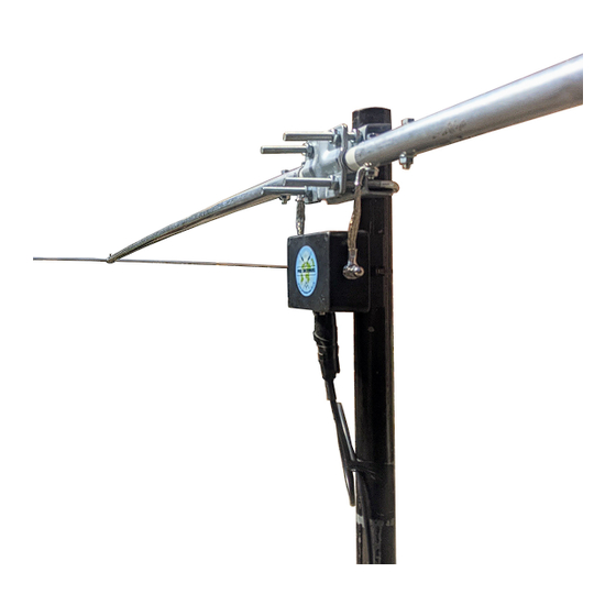
Dual Beam Pro
Assembly Instructions
Dual Beam Pro
Thank you for purchasing this unique antenna product. We
Rotatable
hope that it will provide you with many hours of operation and
pleasure for years to come.
Please take a little time to carefully follow the instructions and
Multi-Band
study the pictures to help understand the correct positioning
and alignment of the various components.
HF Antenna
Contents
The packing tube should contain:
2 x 1 inch diameter alloy 2.5m main element sections
complete with end caps and capacity hat securing bolts
2 x 3/8 inch diameter alloy 2.5m capacity hat elements
1 x GRP rod centre support insulator
The small box should contain:
1 x matching transformer with mounting block
2 x cable ties
2 x matching transformer connection leads
1 x galvanised mast head support clamp
4 x 35mm M6 bolts with serrated nuts
4 x capacity hat element end caps
1 x self amalgamating tape for sealing the cable connector
Assembly Instructions
Tools required
10mm and 13mm spanners
Safety
GRP/aluminium splinters can cause skin irritation and
protective gloves must be worn before handling.
Ensure you have a safe working area of at least 5m x 3m.
Pro Antennas © 2021
Abide by the Work at Height Regulations for installation.
Advertisement

Related Manuals for Pro Antennas Dual Beam Pro

Summary of Contents for Pro Antennas Dual Beam Pro
- Page 1 Dual Beam Pro Assembly Instructions Dual Beam Pro Thank you for purchasing this unique antenna product. We Rotatable hope that it will provide you with many hours of operation and pleasure for years to come. Please take a little time to carefully follow the instructions and...
- Page 2 Fit the Alignment serrated nuts finger tight. The Dual Beam Pro may be mounted on a mast rotator or pre- aligned in the preferred directions of coverage. The diagram below shows the antenna aligned to beam maximum energy 4.
- Page 3 GRP rod and that the connection lead nuts capacity hat elements are cable ties are tight. horizontally aligned before finger tightening the mast Your Dual Beam Pro is head clamp bolts. now ready for use.
Need help?
Do you have a question about the Dual Beam Pro and is the answer not in the manual?
Questions and answers