Table of Contents

Subscribe to Our Youtube Channel
Related Manuals for Auto Meter BCT-468


Summary of Contents for Auto Meter BCT-468
- Page 1 � BCT-460/468 Operator's Manual Hand Held-Accuracy with a Pulsed 120 Amp Load Heavy Duty The BCT Tester is the ultimate hand-held tester. It is the industry's answer to portability in a professionally accurate load tester and system analyzer.
-
Page 2: Specifications
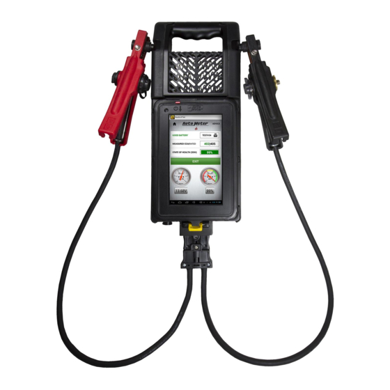
LED, Wide Viewing Angle Volt Ranges ............Digital 0-30 Cooling ..............Vented Leads ..............Load Amp-4 ft., 6 Gauge Size ..............19" BCT-460, 20” BCT-468 X 9" X 3" Internal Battery .............7.4 Volt Lithium Ion Weight ..............7 lbs. What to Expect from the BCT-460/468:... -
Page 3: Table Of Contents
TABLE OF CONTENTS Specifications ..................2 User Agreement................... 2 Table of Contents................. 3 Safety ....................4 Inspection and Visual Check ............... 5 Wireless Communication ..............6 Controls and Functions/Review Results/About ........6-8 Set Up ....................9 Tester Configuration/Settings .............. 10 Replacement Parts and Accessories ........... -
Page 4: Safety
SAFETY Carefully read all operating instructions before using the BCT Tester. Wear eye protection when working around batteries. Be sure each test is completed before removing load clamps to prevent arcing and potential explosion from battery gases. Never remove load clamps while testing. -
Page 5: Inspection And Visual Check
INSPECTION Valid heavy duty electrical system testing depends on all the components being in good operating condition. In addition, the battery MUST have sufficient charge for testing. Carefully perform the following steps before attempting any electrical diagnosis. VISUAL CHECK Inspect Belts for cracks, glazed surface and fraying. Tighten loose belts. Inspect Battery for terminal corrosion, loose or broken posts, cracks in the case, loose hold-downs, low electrolyte level,... -
Page 6: Wireless Communication
WIRELESS COMMUNICATION BLUETOOTH The BCT Tester uses Bluetooth to communicate between the control module and load module. This allows you to make the connections, remove the control module and the run the tests from inside the vehicle. The BCT Tester control module and load module come paired from the factory. Bluetooth will work as long as the distance between the load module and control module is less than 30 feet. - Page 7 CONTROLS AND FUNCTIONS cont. Voltage drop lead connectors Temperature Sensor Charging and Amp Clamp Port Screw to replace leads USB Type A Status LED USB Type B Control Module Latch BCT-460 & 468 I/O Items USB Type A - Factory use only. Temperature Sensor: The Load module has an USB Type B - Factory use only.
- Page 8 CONTROLS AND FUNCTIONS cont. Touch the 3 dots at upper Touch the 3 dots at right corner, then touch upper right corner, Check for Update which then touch Battery allows the user to update Status to show the both the Control modules state of charge of the application or the Load batteries in the Control...
-
Page 9: Set Up
SET UP Touch the 3 dots in the upper right corner OPTION MENU DETAILS to open the menu shown. Allows pairing to Bluetooth Devices. Update Control Module and Load Module software. Check Battery Status. Show list of Test Results. Adjust Control Module volume. Quick Main Menu help. -
Page 10: Tester Configuration/Settings
TESTER CONFIGURATION To access, from home screen touch settings Dealer Information For use with AMPNET. Set if email is desired for test result. Default Email: Email will be sent to the account associated with AMPNET Subscription. Customer Email: Allows the customer to provide a new email address to receive results. -
Page 11: Replacement Parts And Accessories
AC-113 Replacement Load Module Battery AC-123 Replacement Yellow Control Module Latch AC-126 Charging Station for BCT-468 AC-129 Replacement Control Module Case Assembly (BCT-460) AC-136 Replacement Control Module for BCT-468 AC-137 Replacement Control Module Case Kit for BCT-468 (No Module/Tablet Included) AC-94 AC-31 AC-102 AC-105... -
Page 12: Hook Up
HOOK UP Note: Brass or lead battery terminal adapters must be used when performing individual battery tests. See page 11 for list of available adapters Connect Red Clamp to Connect Black Clamp to Positive (+) Terminal Negative (-) Terminal CONNECTION ERRORS If the clamps are reversed the Reversed Connection warning will be displayed on the Control Module with an audible beeping. -
Page 13: Heavy Duty Pm Test
HEAVY DUTY PM TEST The Heavy Duty PM test is intended to only be used during a time when the vehicle is in the shop for a Preventative Maintenance service. Touch Enter the Enter the battery Heavy number of information. Duty PM batteries When you enter... - Page 14 HEAVY DUTY PM TEST (cont.) Please This screen Follow the wait shows the proper on screen a few connections. prompts, moments then touch until the The Current battery is Probe will only tested. show if it was chosen earlier. The battery This screen test results only shows for...
- Page 15 HEAVY DUTY PM TEST (cont.) Running Follow the The test is Starter Test. on screen finished. Turn off prompts. the engine, and touch OK. The charging system is now being tested. Choose the Return to Idle. Starting System number of Touch OK.
- Page 16 HEAVY DUTY PM TEST (cont.) Charging results (with no current probe used). This will show voltage regulation & diodes results. Touch exit to continue. Test Summary will now be displayed. Touch Next, this will bring you back to the home screen.
-
Page 17: Full System Tests
FULL SYSTEM TEST The Full System Test is intended to be used in Heavy Duty applications where there is a suspected electrical system fault. From Does the Connect as Home vehicle have shown, then Screen an auxiliary touch Ok. touch Full battery pack? System Answer (touch) - Page 18 FULL SYSTEM TEST Follow Here are Choose how prompt and your battery many batteries touch Save results. were replaced Touch next to then touch OK. continue. Touch Start If earlier you Connect Battery Test chose that both sets the vehicle is of leads equipped with as shown,...
- Page 19 FULL SYSTEM TEST Battery Follow this Follow on pack diagram. screen results. Probe prompt. Touch next placement is The tester to continue. important for will recognize proper results. when the Be sure it is engine is placed on the cranked and cable between started.
- Page 20 FULL SYSTEM TEST Please wait. Review Once idling No action results, then touch Ok. needed. touch MORE RESULTS. Please wait. Turn off Review No action engine then results then needed. touch Ok. touch NEXT.. Follow on Review Review screen results then results, then prompt.
- Page 21 FULL SYSTEM TEST Review Follow this This screen results, then diagram. will not always touch Next. . Starter post appear. It only adapters are appears if more available information is through needed for the AutoMeter current test. Products for easier con- nections in tight areas.
- Page 22 FULL SYSTEM TEST Follow on Touch Ok. Follow this screen diagram. prompt then touch Ok. Alternator post adapters are available through AutoMeter Products for easier connections in tight areas. Start Engine, Review Touch the the tester will results, then red Enter recognize touch NEXT box to enter...
- Page 23 FULL SYSTEM TEST With Good Start engine Follow on Charging as prompted. screen VDROP prompts, (as shown), then touch touch Next. If failed VDROP, follow on screen prompts for repair and retest. Touch START Press when Review to continue (voltage) is results, stable.
- Page 24 FULL SYSTEM TEST Here you can check any replaced components, or add notes, then touch Done. If nothing replaced, and no notes, you can simply touch Done. At the end of the test, if you are connected to WiFi, and using AMPNET, the tester will automatically...
-
Page 25: Light Duty Pm Test
LIGHT DUTY PM TEST The Light Duty PM Test is a preventative maintenance test for vehicles with 1 individual battery. From the Connect the Touch START Home screen, large leads/ BATTERY Touch Light clamps, TEST to Duty PM Test. then touch continue. -
Page 26: Starter Test
LIGHT DUTY PM TEST Make any Touch START Running necessary to continue Starter Test. repairs to continue. This screen will not show if the result was GOOD BATTERY. Touch Please wait a This message (Did PROCEED few moments the vehicle crank) TO STARTER while the will pop up if the... -
Page 27: Alternator Test
LIGHT DUTY PM TEST Alternator test If more results. information is needed, this You may now shut screen may the engine off. appear. Touch EXIT to continue Choose the number of cylinders, then touch Once reviewed, touch Starter test Next, which will take you results. -
Page 28: Battery Test
INDIVIDUAL TESTS (BATTERY TEST) Select Individual Tests from the main menu. Then select battery test. Select battery test. When the Select Battery Rating area is pressed, the battery rating type can be changed by tapping on the rating type you need. The rating can be changed by pressing Enter, then a keyboard will appear and the rating can be typed... - Page 29 INDIVIDUAL TESTS (BATTERY TEST) When the Select Battery Type area is pressed, the battery type can If the engine is running the be selected. Press the battery type charging system will affect the you are testing and the unit will go battery test.
- Page 30 INDIVIDUAL TESTS (BATTERY TEST) The battery passed the test but The battery did not have had a low initial voltage. a sufficient charge to do Charge the battery and then an accurate test. Charge return to service. the battery and then test the battery.
- Page 31 INDIVIDUAL TESTS (STARTER TEST W/O PROBE) From home Start the Connect as screen, touch shown. Engine. Individual Test, then touch Starter Test. Press the Start The BCT Tester Leave box key to begin the will monitor the “unchecked” test. The unit starter current regarding use of will take some...
- Page 32 INDIVIDUAL TESTS (STARTER TEST W/O PROBE) Good Starter. Failed Starter...
- Page 33 INDIVIDUAL TESTS (STARTER TEST W/PROBE) From home page Connect as Start the touch Individual shown. Engine Test, then touch Starter Test. Be sure check box is “checked” then touch ok. Turn the key to The BCT Tester the run position. ask if the vehicle Wait for the ECU cranks.
- Page 34 INDIVIDUAL TEST (Starter Test) No Crank Situation This test will determine The BCT Tester will show the user whether the problem is how to connect with the starter. large red clamp to starter positive. Connect large black clamp to starter ground. Connect small red clamp to start enable input.
- Page 35 INDIVIDUAL TEST (Alternator Test) From the home The BCT Tester screen, touch will make some Individual Test, then preliminary touch Alternator measurements Test. to prepare for the alternator test. Connect as shown. Touch Enter, then Start the Engine Enter the rated alternator output.
- Page 36 INDIVIDUAL TEST (Alternator Test) While the engine is at governor speed the unit will look for low and high regulation and measure the output current and the ripple. If the BCT Tester When the test is determines that more loads complete the BCT are needed to fully test the Tester will instruct...
- Page 37 INDIVIDUAL TEST (Alternator Test) The results of the test will be displayed. Any failure will be highlighted in red. If the alternator fails due to high voltage regulation and it has remote sense the BCT Tester will instruct the user to disconnect the remote sense wire and repeat the governor speed test.
-
Page 38: Starter Cable Test
VOLTAGE DROP TEST (Starter Cable Test) The voltage drop test allows you to measure the voltage drop across both the positive and negative cables running from the battery to the starter and alternator or any other device within your vehicle. This test can be used to deter- mine if the cables or connections are the cause of any problems. -
Page 39: Voltage Drop Tests
VOLTAGE DROP TEST (Charging Cable Test) Select individual tests, then To set the test select the V DROP Test from current, press the Test current box the main menu. and a numeric keypad will appear. Enter in the alternator output for the vehicle you are testing. -
Page 40: Generic Cable Test
VOLTAGE DROP TEST (Generic Cable Test) Select individual tests, then To set the test current, select the V DROP Test press the Test current box from the main menu. and a numeric keypad will appear. Enter in the test current for the circuit you are testing. -
Page 41: Magnetic Circuit
VOLTAGE DROP RESULTS If the voltage drop is high the If the combined voltage drop of test will return a bad result. the positive and negative circuit The cable that is bad can be is less than 500mV, the voltage determined by looking at the drop test passes. -
Page 42: Voltmeter
USING THE OPTIONAL CURRENT PROBE The Current Probe is optional. This section explains the proper use of the Current Probe, but is not required to run any of the tests. It only provides assured accuracy for those wanting these results. When the probes is not clamped around a cable push and turn to Zero the current probe. -
Page 43: Ampnet
AMPNET The BCT is equipped with the ability to automatically send test data to what is called an AMPNET server. AMPNET is accessible with a paid, 1-time, lifetime subscription. With AMPNET, your tester will automatically store all of the information about the vehicle, that is entered in at the beginning of the test (such as, but not limited to: VIN, Mileage, Technician, Etc..), as well as the test results. -
Page 44: Troubleshooting
TROUBLESHOOTING PROBLEM SOLUTION BCT Tester Does Not Read This is most commonly due to the LM (load module) not powered on, or a loss of BlueTooth Battery Temperature connection between the CM (control module/Tablet) and LM. 1) Make sure the LM is powered on & charged. Observe the LED indicator. If the indicator is not lit, push and release the LM button to “wake up”... - Page 45 TROUBLESHOOTING The Control Module will not turn On the Control Module (CM), hold the power button for at least 5 seconds. on due to a completely discharged If the CM still does not turn on, place the CM into the Load Module. Place the entire unit into the Control Module battery wall mounted charging station, and look for the Load Module's LED to go to a solid, or blinking red.
-
Page 46: Warranty
LIMITED WARRANTY 12 MONTHS FROM DATE OF PURCHASE The manufacturer warrants to the consumer that this product will be free from defects in material or workmanship for a period of twelve (12) months from the date of original purchase. (90 days for cables and clamps. -
Page 47: Contact Information
Auto Meter Products Inc. � �� � � ��� �� ��� 350 West Center Street Pleasant Grove, Utah 84062 AutoMeter Products Inc. Service (801) 785-0051 ext. 223 413 West Elm Street Toll Free (866) 883-TEST (8378) Sycamore, IL 60178 Fax (801)785-8699 www.autometertest.com...
Need help?
Do you have a question about the BCT-468 and is the answer not in the manual?
Questions and answers