Hitachi UX2 Series Basic Operation Manual
Ij printer
Hide thumbs
Also See for UX2 Series:
- Instruction manual (300 pages) ,
- Technical manual (184 pages) ,
- User manual (69 pages)
Table of Contents
Advertisement
Quick Links
HITACHI
Basic Operation Manual
● This manual describes the basic operating procedures for the printer.
● Before using the printer, thoroughly read the separate instruction manual
for optimum printer use.
● After reading this basic operation manual, properly keep it for future
reference.
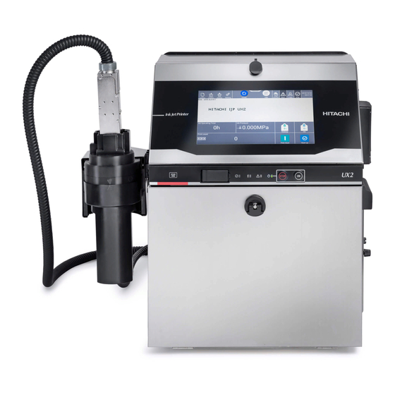
Model UX2
Printer
i
Advertisement
Table of Contents

Related Manuals for Hitachi UX2 Series


Summary of Contents for Hitachi UX2 Series
- Page 1 HITACHI Printer Model UX2 Basic Operation Manual ● This manual describes the basic operating procedures for the printer. ● Before using the printer, thoroughly read the separate instruction manual for optimum printer use. ● After reading this basic operation manual, properly keep it for future...
-
Page 2: Table Of Contents
Contents ● Important Notes ● Safety Precautions ● Preface Chapter 1. Delivered Items and Accessories ............1.1. Delivered Items and Accessories ....................Chapter 2. Component Names and Functions ............2.1. External Views ..........................2.2. Unit Internal Parts Arrangement ....................2.3. Print Head ............................2.4. -
Page 3: Delivered Items And Accessories
Chapter 1. Delivered Items and Accessories 1.1. Delivered Items and Accessories... - Page 4 Chapter 1. Delivered Items and Accessories 1.1. Delivered Items and Accessories The delivered items and accessories are shown in the table below. Item code Item name Quantity Remarks IJ Printer Basic Operation Manual This manual. Used to check the shape of ink drop and Magnifying glass 451274 the position of ink stream.
- Page 5 Chapter 1. Delivered Items and Accessories Item code Item name Quantity Remarks When connecting the LAN cable to the IJ Printer, put one core around the cable outside the printer and the other through one loop of the cable inside the printer as shown below.
-
Page 6: Chapter 1. Delivered Items And Accessories
Cleaning unit filter installation. (One of the two is a spare.) Recovery bottle For managing the start date of use of the label recovery bottle To order an accessory, please let Hitachi know the "item name" and the "item code No.". -
Page 7: External Views
Chapter 2. Component Names and Functions 2.1. External Views 2.1. External Views2.2. Unit Internal Parts Arrangement 2.3. Print Head 2.4. Head Cleaning Unit 2.5. Screen Display... - Page 8 Chapter 2 Component Names and Functions This chapter describes the names and functions of components of this unit. 2.1. External Views (1) External views (front side) The external views of the unit are as follows. Operating status indicator Operation screen lamps Used to operate this unit.
- Page 9 Chapter 2 Component Names and Functions (UX2-D160W with clearing station) Head cleaning unit (2) External views (rear side) Signal connection ports Built-in antenna part Filter cover Air-purge connection Exhaust duct port connection port Precautions for use Stainless steel of the main body is not easily rusted, but it may be affected by the environment or cause rust if the unit is left for a long time.
- Page 10 Chapter 2 Component Names and Functions (UX2-D160W with clearing station) Cleaning unit connecting tube...
- Page 11 Chapter 2 Component Names and Functions 2.2. Unit Internal Parts Arrangement The internal structure of the unit is as follows. Inner cover Makeup cartridge bottle 1 (*1) Ink cartridge bottle Makeup (*1) reservoir Ink reservoir Lever handle Lever handle Ink pressure adjusting screw Appearance with inner cover removed Ink filter...
- Page 12 Chapter 2 Component Names and Functions 2.3. Print Head The internal structure of the print head is as follows. UX2-D160W (Standard model) UX2-D160W with cleaning station The ends of the print head Head cover lock screw cover and the gutter are Loosen to remove the print different from those of the head cover.
- Page 13 Chapter 2 Component Names and Functions 2.4. Head Cleaning Unit (Cleaning Station) The structure of the head cleaning unit is as follows. Left perspective view Right perspective view Head cover rest Print head slot Slide block Place the print head Inlet into which the print Used to mount the head cover temporarily.
- Page 14 Chapter 2 Component Names and Functions 2.5. Screen Display <<[HOME] screen>> The [HOME] screen appears mostly when the power is turned ON. Communication status: Displays online or offline. Status: Indicates the status of the unit. Current time Menu bar Manual control menu button: Login: Indicates the login status.
- Page 15 Chapter 2 Component Names and Functions The [Warning] message is displayed in orange. It contains the detail, cause, and solution. Solve the problem according to the instruction in the message. Message type Message name Message No. Description Cause Solution Button The [Fault] message is displayed in red.
-
Page 17: Chapter 3. Basic Operation
Chapter 3. Basic Operation 3.1. Start Operation 3.2. Shutdown Operation 3.3. Print Head Cleaning... -
Page 18: Procedure For Starting Operation
Chapter 3 Basic Operation 3.1. Start Operation This section describes how to start the unit. Required operations are explained in detail, including the procedure for starting the unit. 3.1.1. Procedure for Starting Operation CAUTION ● Ink and makeup may contain organic solvents. When handling ink or makeup, wear protective gloves and goggles so that it does not come in direct contact with your skin ●... - Page 19 Chapter 3 Basic Operation Turn ON the main power switch to turn on the power. Operating status indicator lamps Displays "Ready", Main power switch "Fault" and "Warning". Turns the unit ON and OFF. ON/STOP switch Starts or stops the unit with the main power on.
- Page 20 Chapter 3 Basic Operation If the [Select login user] screen appears when the power is turned on Turn on the power. The [Select login user] screen appears. Select any user. The saved user names are displayed. An icon showing a binder An icon showing no binder represents a user with represents a general user.
- Page 21 Chapter 3 Basic Operation Place a piece of wiping paper, etc., against the ink ejection port at the end of the print head to be ready for ink ejection. (* Immediately after ink ejection, a little amount of ink may spurt out and soil the surroundings.) Print head Wiping paper, etc.
- Page 22 Chapter 3 Basic Operation Note: If ink continuously splashes and soils the wiping paper even when not printing, there may be some fault in the print head, such as the ink stream not entering the gutter or the ink not being recovered from the gutter.
- Page 23 Chapter 3 Basic Operation Wait until the status changes from [Starting] to [Ready]. ● When this unit is used at a low temperature (approximately 25 ℃ or lower), it may take longer than usual for the printer to enter the [Ready] state. ●...
-
Page 24: When Error Occurs At Start Of Operation
Chapter 3 Basic Operation 3.1.2. When Error Occurs at Start of Operation Make sure that the unit is in the [Stop] state. Loosen the head cover lock screw and remove the print head cover. Head cover lock screw Loosen to remove the print head cover. - Page 25 Chapter 3 Basic Operation Remove the print head cover and put the end of the print head in the beaker to be ready for ink ejection. Press Startup at the bottom right of the [HOME] screen. Press Startup. Press Eject ink. ●...
- Page 26 Chapter 3 Basic Operation Make sure that the ink stream is at the center of the gutter. WARNING ● Wear protective gear (goggles and mask) when checking the position of the ink stream. ● If any ink or makeup enters your eyes or mouth, immediately flush with warm or cold water and consult a physician.
-
Page 27: Ready And Standby State Switching Operation
Chapter 3 Basic Operation 3.1.3. Ready and Standby State Switching Operation (1) Switching from [Ready] state to [Standby] state * When the conveyor interlock is activated by the [Ready] output signal, if the status is changed to [Standby], the conveyor will stop. Press Ready at the top of the screen, and the [Print Abort Confirmation] message appears. - Page 28 Chapter 3 Basic Operation (2) Switching from [Standby] state to [Ready] state Press Standby at the top of the screen, and the [Print Confirmation] message appears. Then, press OK. Press Standby. Press OK. 3-12...
-
Page 29: Shutdown Operation
Chapter 3 Basic Operation 3.2. Shutdown Operation 3.2.1. Automatically Stopping by Pressing STOP Switch Button Press and hold the STOP switch for about two seconds. All operations up to the unit power OFF are performed automatically. Operating status indicator lamps Main power switch Displays "Ready", "Fault"... -
Page 30: Stopping Ink Ejection By Pressing Screen Button
Chapter 3 Basic Operation 3.2.2. Stopping Ink Ejection by Pressing Screen Button ● Use the following procedure to stop ink ejection. Procedure to stop ink ejection Press Shutdown at the bottom right of the [HOME] screen. Press Shutdown. Turns OFF the power automatically after ink jet is stopped, like the STOP switch. Stops ink ejection without cleaning the circulation route. -
Page 31: Turning Off Main Power Switch
Chapter 3 Basic Operation 3.2.3. Turning Off Main Power Switch When turning off the main power switch, note the following. ● Normally, press the STOP switch instead of the main power switch to turn off the power at the end of operation. -
Page 32: Print Head Cleaning
Chapter 3 Basic Operation 3.3. Print Head Cleaning This section describes the cleaning procedure when the area around the nozzle is soiled by ink. 3.3.1. Cleaning with Cleaning Bottle (1) Face the end of the print head downward and pour makeup onto the dirty part and clean while catching the makeup in a beaker. - Page 33 Chapter 3 Basic Operation (*) When using the cartridge bottle makeup as a cleaning solution (a) Open the makeup cartridge bottle by turning its cap. At this time, do not remove the over cap. Over cap Makeup cartridge bottle (b) Use the makeup by transferring it to the cleaning bottle. Cleaning bottle Notes: ●...
- Page 34 Chapter 3 Basic Operation 3.3.2. Cleaning with cleaning station WARNING ● Solvent steam is produced during head cleaning. If you have no choice but to touch the print head or head cleaning unit during head cleaning, be sure to remove static electricity from your body before the operation.
- Page 35 Chapter 3 Basic Operation Operation procedure Make sure that the unit is in the [Standby] or [Stop] state. Status: Indicates the status of the unit. Make sure that the recovery container of the head cleaning unit is correctly installed. ● Make sure that the "▽" mark on the main unit side of the head cleaning unit is aligned with the "△" mark on the recovery container.
- Page 36 Chapter 3 Basic Operation Loosen the head cover lock screw and remove the print head cover. Head cover lock screw Pull out Print head cover Make sure that the print head cover is not lost after it is removed, such as by hanging it on the head cover rest for the head cleaning unit.
- Page 37 Chapter 3 Basic Operation Insert the print head into the print head slot of the head cleaning unit in the direction indicated in the figure below. Print head Insert Print head slot NOTE ● Do not insert the print head into the head cleaning unit forcibly. Otherwise, some part may deform, fall off, or be damaged.
- Page 38 Chapter 3 Basic Operation Press the [Manual Control Menu] button on the [HOME] screen to display the [Manual Control Menu] screen. Press Manual Control Menu. Press the [Head washing] button on the [Manual Control Menu] screen. Press Head washing. The [Confirm] message appears. The following describes how to perform head cleaning when the unit is in the [Stop] state and when in the [Standby] state.
- Page 39 Chapter 3 Basic Operation <<When performing head cleaning in the [Stop] state>> (1) The following [Confirm] message appears. Press [Head washing]. Press Head washing. (2) When the cleaning starts, the following screen appears. The set cleaning mode is displayed. Cleaning mode Display Eco head washing @Standard@...
- Page 40 Chapter 3 Basic Operation <<When performing head cleaning in the [Standby] state>> Operations from ink stop to head cleaning are automatically performed. (1) The following [Confirm] message appears. Make sure that the print head is inserted into the head cleaning unit and press [OK]. Press OK.
- Page 41 Chapter 3 Basic Operation Remove the print head from the head cleaning unit and make sure that the area around the nozzle including the end of the print head is cleaned and the makeup is dried up. Around nozzle End of the print head NOTE ●...
- Page 42 Chapter 3 Basic Operation Remove the recovery container from the head cleaning unit and drain the makeup in the container. <<How to remove the recovery container>> Hold and turn the recovery container until its "△" mark is aligned with the "〇" mark on the head cleaning unit.
-
Page 44: Chapter 4. Ink And Makeup Replenishment
Chapter 4. Ink and Makeup Replenishment 4.1. Replenishing Ink 4.2. Replenishing Makeup... - Page 46 Chapter 4. Ink and Makeup Replenishment 4.1. Replenishing Ink This section describes how to replenish ink in this unit. It also provides ink replenishment timing and precautions. (1) Overview ● Ink can be refilled when the remaining ink icon is positioned in a range where the cartridge bottle can be replaced.
- Page 47 Chapter 4. Ink and Makeup Replenishment (2) Replenishment procedure NOTE ● Do not lift the cartridge bottle by holding the over cap. Otherwise, the cartridge bottle may fall. ● Since the cartridge bottle contains an IC chip, avoid strong shock/electromagnetic waves or liquid leakage.
- Page 48 Chapter 4. Ink and Makeup Replenishment Hold the IC tag mark of the label on the cartridge bottle over the RFID reader of the printer to read the ink ID. NOTE ● If there is ink remaining in the cartridge bottle even when the bottle is replaceable, do not replace it but contact your nearest local distributor because some part may be broken.
- Page 49 Chapter 4. Ink and Makeup Replenishment -1 If you manually input the ID, touch the icon on the [HOME] screen of the unit to open the ID input screen and input the ink ID. ● The ink ID is printed on the label of the cartridge bottle. Ink ID Icon...
- Page 50 Chapter 4. Ink and Makeup Replenishment -2 Manually input the ink ID in the ID input area. To toggle between uppercase and lowercase characters, use * If the ID is too stained by ink to be read, contact your nearest local distributor.
- Page 51 Chapter 4. Ink and Makeup Replenishment When the ink ID is recognized, the lever handle on the ink side is unlocked. (1) Tilt the lever handle toward yourself, (2) lift it, and (3) remove the cartridge bottle. NOTE ● If the lever handle cannot be lifted, do not pull it with excessive force but push the lever handle all the way in.
- Page 52 Chapter 4. Ink and Makeup Replenishment Set a new cartridge bottle in the specified position. Install the boss of the cartridge bottle on the boss guide of the ink supply port. Set a new cartridge bottle. Ink side Ink supply port Boss guide Align the boss with the guide.
- Page 53 Chapter 4. Ink and Makeup Replenishment When a new cartridge bottle is set, push the lever handle down and then push it all the way into the unit. CAUTION ● Be careful not to get your hand or fingers pinched when pushing down the lever handle. (See the figure below.) Lever handle Lever handle...
- Page 54 Chapter 4. Ink and Makeup Replenishment The cartridge replacement (ink refilling) is now completed. Press Complete on the guidance screen of the unit. Pressing Complete confirms that ink refilling is complete. Complete 4-10...
- Page 55 Chapter 4. Ink and Makeup Replenishment 4.2. Replenishing Makeup This section describes how to replenish makeup in this unit. It also provides makeup replenishment timing and precautions. (1) Overview ● Makeup can be refilled when the remaining makeup icon is positioned in a range where the cartridge bottle can be replaced.
- Page 56 Chapter 4. Ink and Makeup Replenishment (2) Replenishment procedure NOTE ● Do not lift the cartridge bottle by holding the over cap. Otherwise, the cartridge bottle may fall. ● Since the cartridge bottle contains an IC chip, avoid strong shock/electromagnetic waves or liquid leakage.
- Page 57 Chapter 4. Ink and Makeup Replenishment Hold the IC tag mark of the label on the cartridge bottle over the RFID reader of the printer to read the makeup ID. NOTE ● If there is makeup remaining in the cartridge bottle even when the bottle is replaceable, do not replace it but contact your nearest local distributor.
- Page 58 Chapter 4. Ink and Makeup Replenishment -1 If you manually input the ID, touch the icon on the [HOME] screen of the unit to open the ID input screen and input the makeup ID. ● The makeup ID is printed on the label of the cartridge bottle. Makeup ID Icon 4-14...
- Page 59 Chapter 4. Ink and Makeup Replenishment -2 Manually input the makeup ID in the ID input area. To toggle between uppercase and lowercase characters, use * If the ID is too stained by ink to be read, contact your nearest local distributor. 4-15...
- Page 60 Chapter 4. Ink and Makeup Replenishment When the makeup ID is recognized, the lever handle on the makeup side is unlocked. (1) Tilt the lever handle toward yourself, (2) lift it, and (3) remove the cartridge bottle. NOTE ● If the lever handle cannot be lifted, do not pull it with excessive force but push the lever handle all the way in.
- Page 61 Chapter 4. Ink and Makeup Replenishment Set a new cartridge bottle in the specified position. Install the boss of the cartridge bottle on the boss guide of the makeup supply port. Set a new cartridge bottle. Makeup side Makeup supply port Boss guide Boss...
- Page 62 Chapter 4. Ink and Makeup Replenishment When a new cartridge bottle is set, push the lever handle down. CAUTION ● Be careful not to get your hand or fingers pinched when pushing down the lever handle. (See the figure below.) Lever handle Lever handle Lever handle...
- Page 63 Chapter 4. Ink and Makeup Replenishment The cartridge replacement (makeup refilling) is now completed. Press Complete on the guidance screen of the unit. Pressing Complete confirms that makeup refilling is complete. Complete * In the unit where the fault [Makeup Level Sensor Broken 1] occurred, the makeup cartridge cannot be replaced until the warning [Makeup Low Warning] appears.
-
Page 66: Chapter 5. Emergency Procedures
Chapter 5. Emergency Procedures... - Page 68 Chapter 5. Ink and Makeup Replenishment This chapter describes the operations to be performed if an emergency such as an earthquake or fire occurs while the unit is running. WARNING ● If an earthquake, fire, or other emergency occurs while the printer is engaged in printing or just turned on, press the main power switch to turn off the power.
- Page 70 Preliminary version 05.07.21 HIES Shibuya...