
Related Manuals for Waters ACQUITY UPLC I-Class Series

Summary of Contents for Waters ACQUITY UPLC I-Class Series
- Page 1 ACQUITY UPLC I-Class Series System Guide 715005704 Copyright © Waters Corporation 2018 Revision A All rights reserved...
-
Page 2: General Information
This document is believed to be complete and accurate at the time of publication. In no event shall Waters Corporation be liable for incidental or consequential damages in connection with, or arising from, its use. For the most recent revision of this document, consult the Waters website (waters.com). -
Page 3: Customer Comments
Contacting Waters Contact Waters with enhancement requests or technical questions regarding the use, transportation, removal, or disposal of any Waters product. You can reach us via the Internet, telephone, fax, or conventional mail. April 4, 2018, 715005704 Rev. A... -
Page 4: Safety Considerations
Milford, MA 01757 Safety considerations Some reagents and samples used with Waters instruments and devices can pose chemical, biological, or radiological hazards (or any combination thereof). You must know the potentially hazardous effects of all substances you work with. Always follow Good Laboratory Practice (GLP), and consult your organization’s standard operating procedures as well as your local... -
Page 5: Power Cord Replacement Hazard
To avoid electric shock, use SVT-type power cords in the United States and HAR-type (or better) cords in Europe. The power cords must be replaced only with ones of adequate rating. For information regarding which cord to use in other countries, contact your local Waters distributor. Hand crush hazard Warning: To avoid hazards associated with the reciprocating or rotating parts in the source, keep hands clear of the regions marked with yellow and gray labels. -
Page 6: Equipment Misuse Notice
Equipment misuse notice If equipment is used in a manner not specified by its manufacturer, protections against personal injury inherent in the equipment’s design can be rendered ineffective. Safety advisories Consult the "Safety advisories" appendix in this publication for a comprehensive list of warning advisories and notices. -
Page 7: Audience And Purpose
I-Class systems. It gives an overview of the system’s technology and operation. Intended use of the ACQUITY UPLC I-Class Series system Waters designed the ACQUITY UPLC I-Class Series system to perform chromatographic separations. The system is for research use only and is not intended for use in diagnostic applications. -
Page 8: Ism Classification: Ism Group 1 Class B
Class B products are suitable for use in both commercial and residential locations and can be directly connected to a low voltage, power-supply network. EC authorized representative Address Waters Corporation Stamford Avenue Altrincham Road Wilmslow SK9 4AX UK Telephone... -
Page 9: Table Of Contents
Safety advisories ..........................vi Operating the system..........................vi Applicable symbols......................... vi Audience and purpose........................vii Intended use of the ACQUITY UPLC I-Class Series system ............vii Calibrating ............................vii Quality control..........................vii ISM classification: ISM group 1 class B ....................viii EC authorized representative ......................viii 1 ACQUITY UPLC I-Class Series System ..............13... - Page 10 1.6 Mass spectrometry........................17 1.7 System components........................17 1.7.1 Binary solvent manager (BSM).................... 18 1.7.2 Sample manager-FTN (SM-FTN) ..................18 1.7.3 Sample manager-FL (SM-FL)....................19 1.7.4 Column heater (CH-A) ......................19 1.7.5 30-cm Column heater (optional) ..................19 1.7.6 Column manager (optional) ....................20 1.7.7 Column heater/cooler (optional) ..................20 1.7.8 Column Module Switch Box (optional).................
- Page 11 3.2.1 To open the console from Empower software ..............43 3.2.2 To open the console from MassLynx software ..............43 3.2.3 To open the console from UNIFI software ................43 3.3 Preparing system hardware ......................44 3.3.1 Powering-on the system ...................... 44 3.3.2 Monitoring module LEDs ..................... 45 3.3.3 Power LED...........................
- Page 12 B.2 Caution advisory ........................... 71 B.3 Warnings that apply to all Waters instruments and devices ............71 B.4 Electrical and handling symbols ....................76 B.4.1 Electrical symbols........................ 76 B.4.2 Handling symbols ........................ 76 B.5 Stacking system modules with interlocking features ..............77 B.6 Stacking system modules without interlocking features ............... 78 April 4, 2018, 715005704 Rev.
-
Page 13: Acquity Uplc I-Class Series System
ACQUITY UPLC I-Class Series System Waters designed the ACQUITY UPLC I-Class Series system for optimum performance when running difficult assays. Configure it with a mass spectrometer to take full advantage of the system’s design enhancements. 1.1 UPLC technology In 2004, Waters made significant advances in instrumentation and column design to introduce UPLC technology to the field of separation science. - Page 14 Figure 1–1: Evolution of particle size in liquid chromatography and the impact on separation efficiency It is apparent from the figure, above, that using 1.7-µm particles achieves higher efficiency that persists as flow rate increases (lower HETP indicates higher efficiency). When operating in this area of the plot, the peak capacity and the speed of a separation can set limits well beyond those of conventional HPLC technology.
-
Page 15: Features Of The Acquity Uplc I-Class Series System
1.2 Features of the ACQUITY UPLC I-Class Series system The ACQUITY UPLC I-Class Series system significantly improves the results of traditionally challenging separations. When compared to systems typically used for difficult assays, the I-Class Series system offers these advantages: •... -
Page 16: Binary Solvent Manager
1.3 Binary solvent manager The ACQUITY UPLC I-Class Series system employs a binary solvent manager that, like the system, is optimized for sub-2-μm particle liquid chromatography and uses reduced fluid volumes. New pressure management capabilities extend the flow rate envelope for the system to support ballistic gradients. -
Page 17: Mass Spectrometry
1.6 Mass spectrometry When you configure an ACQUITY UPLC I-Class Series system with a mass spectrometer, the system’s design enhancements enable you to separate more peaks with better peak shapes to aid quantitation. You also benefit from improvements in sensitivity and flexibility. -
Page 18: Binary Solvent Manager (Bsm)
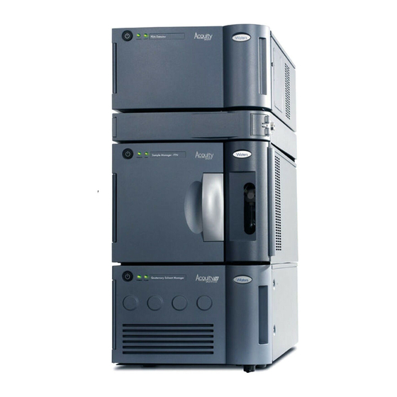
Sample manager Binary solvent manager The ACQUITY UPLC I-Class Series core system includes a binary solvent manager, a sample manager - flow through needle or sample manager - fixed loop (SM-FTN or SM-FL), a column heater (CH-A), detectors (tunable ultraviolet, photodiode array, eλ photodiode array, or mass spectrometry), and an ACQUITY UPLC column. -
Page 19: Sample Manager-Fl (Sm-Fl)
See also: ACQUITY UPLC Sample Manager - Fixed Loop PLUS Overview and Maintenance Guide on your documentation media, or at Waters.com, for more information on other injection modes. 1.7.4 Column heater (CH-A) Column temperature variations can shift peak retention times and alter peak shapes, increasing the difficulty of achieving precise results. -
Page 20: Column Manager (Optional)
1.7.6 Column manager (optional) The ACQUITY UPLC I-Class Series column manager (CM-A) is an option for helping to ensure precise, reproducible separations. The CM-A can regulate the temperature of columns from 4 °C to 90 °C. Its troughs can accommodate columns of up to 4.6-mm I.D. and up to 150-mm length, depending on the configuration. -
Page 21: Sample Organizer (Optional)
Note: The ACQUITY FlexCart is not supported with the ACQUITY QDa detector or any ACQUITY UPLC I-Class Series system with dual detection (split-stack configurations). 1.7.11 Column technology The ACQUITY UPLC columns are packed with the following: 1.7-µm, bridged, ethylsiloxane, hybrid;... -
Page 22: Detection
1.7.11.1 eCord technology ACQUITY UPLC columns include an eCord column chip that tracks the usage history of the column. The eCord column chip interacts with the system software, recording information for as many as 50 sample queues run on the column. In regulated environments, the eCord column chip provides documentation of the column used in the validation method. - Page 23 • ACQUITY UPLC Column Compartments Operator's Overview and Maintenance Information • ACQUITY UPLC Sample Organizer Overview and Maintenance Guide Visit Waters.com to find more information and to join the ACQUITY UPLC online community, where you can: • Share information and ask questions of ACQUITY UPLC experts and scientists.
-
Page 24: Performance Optimization
When performing fast UPLC analyses, a peak of interest can be less than 0.5 seconds. Waters recommends a sampling rate of 25 to 50 points across the peak, which provides good quantitation and peak representation. -
Page 25: Dispersion
An ACQUITY UPLC I-Class Series system typically exhibits a bandspread (5σ) of ≤ 7µL or ≤ 9µL when configured with an SM-FL or SM-FTN, respectively. An Alliance HPLC system can exhibit a bandspread between 35 µL and 50 µL. -
Page 26: Carryover
2.3 Carryover You observe carryover in chromatographic systems when a previously injected analyte appears as a peak in the chromatogram of subsequent samples. Carryover tends to occur when a small amount of analyte remains in the system after a sample is injected. You can measure carryover by observing analyte peaks that appear when you run a blank sample immediately after an analytical sample. -
Page 27: Cycle Time (Between Injections)
Leaks at high-pressure fittings (downstream of the i2Valves) can leak solvent but do not introduce air. To prevent leaks, follow Waters’ recommendations for the proper tightening of system fittings. Note specifically that different techniques apply to retightening fittings versus installing them for the first time. - Page 28 Requirement: Use eye protection when performing this procedure. Recommendations: • To prevent band spreading, ensure that the tubing is fully bottomed in its connection port before tightening the compression screw. • For easier accessibility, use long compression screws to attach tubes to the injector and vent valve.
- Page 29 Rotate the compression screw, clockwise, into the connection port until the screw is finger- tight. Using a permanent marker, mark the compression screw at the 12-o’clock position. Mark the connection port at the 9-o’clock position. Ensure that the tubing makes contact with the bottom of the connection port, and use the 1/4-inch open-end wrench to rotate the compression screw clockwise 3/4-turn until the two marks line up.
- Page 30 First use tightening Reinstalled Long flats Compression screw 2-piece stainless steel ferrule Tighten the fitting finger-tight plus as much as an additional 1/6-turn using a 1/4-inch open-end wrench. Reinstalled tightening April 4, 2018, 715005704 Rev. A Page 30...
- Page 31 2.7.1.3 Stainless steel (gold-plated) fitting with short flats and 2-piece stainless steel ferrule (V-detail) First use Short flats Compression screw 2-piece stainless steel ferrule Tighten the fitting finger-tight plus an additional 3/4-turn using a 1/4-inch open-end wrench. For detailed instructions about assembling new fittings, see Assembling new fittings.
- Page 32 Short flats Compression screw 2-piece stainless steel ferrule Tighten the fitting finger-tight plus as much as an additional 1/6-turn using a 1/4-inch open-end wrench. Reinstalled tightening 2.7.1.4 1/4-28 flangeless fitting with ferrule First use or re-installed Compression screw Ferrule Tighten the fitting finger-tight. April 4, 2018, 715005704 Rev.
- Page 33 2.7.1.5 1/4-28 flangeless fitting with 2-piece ferrule First use or re-installed Compression screw 2-piece ferrule Tighten the fitting finger-tight. 2.7.1.6 Long 1/4-28 fitting with flangeless ferrule and stainless steel lock ring installed on 1/8-inch OD tubing First use or re-installed Compression screw Lock ring Ferrule...
- Page 34 2.7.1.7 Short 1/4-28 fitting with flangeless ferrule and stainless steel lock ring installed on 1/16-inch OD tubing First use or re-installed Compression screw Lock ring Ferrule End of lock ring with larger inside diameter (ID) Tighten the fitting finger-tight. 2.7.1.8 5/16-24 fitting with filter and stainless steel lock ring First use or re-installed Compression screw Lock ring...
- Page 35 2.7.1.9 PEEK fitting with PEEK ferrule and stainless steel lock ring First use or re-installed Compression screw Lock ring Ferrule Tighten the fitting finger-tight. 2.7.1.10 One-piece PEEK fitting Figure 2–1: First use or reinstalled Compression screw Tighten the fitting finger-tight. Tips: •...
- Page 36 Figure 2–2: APH outlet fitting first use or reinstalled #1 knurled compression fitting #2 locking cap nut Back-locking PEEK ferrule Figure 2–3: Column-stabilizer outlet fitting first use or reinstalled #1 hex compression fitting #2 locking cap nut Back-locking PEEK ferrule April 4, 2018, 715005704 Rev.
- Page 37 Figure 2–4: Legacy fitting first use or reinstalled Hex compression fitting Locking cap nut Back-locking or standard PEEK ferrule To tighten the fitting: Loosen the cap nut from the compression fitting. Slide the compression fitting together with the ferrule into the inlet of the column (or the in- line filter).
- Page 38 Compression fitting Column gripping tool Column Tip: If you are operating the system at, or close to, its maximum system operating pressure limit and the fitting is a hex, use the 1/2-inch open-end wrench to tighten the compression fitting an additional 1/8- to 1/6-turn. Tighten the cap nut onto the compression fitting.
- Page 39 Figure 2–6: Unscrewing cap nut from fitting #1 knurled compression fitting #2 locking cap nut Slide the #1 knurled compression fitting off the tubing. Figure 2–7: Sliding fitting off tubing #1 knurled compression fitting Tubing Note: If the assembly contains a captive ferrule, the ferrule remains locked in the fitting. If the assembly contains a captive ferrule, remove the ferrule from the fitting.
- Page 40 Figure 2–8: Removing ferrule from fitting #1 knurled compression fitting Ferrule (captive ferrule shown) Discard the used ferrule. Install the new ferrule on the fitting. Slide the #1 knurled compression fitting and ferrule onto the tubing. Figure 2–9: Sliding fitting and ferrule onto tubing Tubing #1 knurled compression fitting Note:...
-
Page 41: Sample Preparation
2.9 Solvent recommendations For more information on recommended solvents for your system, refer to ACQUITY UPLC H- Class, H-Class Bio, and I-Class Series Systems Solvent Considerations on your documentation media, or visit Waters.com. April 4, 2018, 715005704 Rev. A Page 41... -
Page 42: System Preparation
The following start-up tests run: CPU board, memory (RAM and ROM), external communication system (Ethernet), and clock. If the start-up tests indicate a malfunction, contact your local Waters representative. Power-on the sample manager and then the solvent manager, by pressing the power switch on the top, left-hand side of each device's door. -
Page 43: Opening The Console
Open the control panels and console. See also: Monitoring control panels Opening the console Prime the system. See also: Priming the system 3.2 Opening the console You can perform the following tasks in the console: • Monitor system performance • Specify settings for certain module parameters •... -
Page 44: Preparing System Hardware
The following start-up tests run: CPU board, memory (RAM and ROM), external communication system (Ethernet), and clock. If the start-up tests indicate a malfunction, contact your local Waters representative. Power-on the sample manager and then the solvent manager, by pressing the power switch on the top, left-hand side of each device's door. -
Page 45: Monitoring Module Leds
See also: Monitoring control panels Opening the console Prime the system. See also: Priming the system 3.3.2 Monitoring module LEDs The LEDs on each module indicate its operational status. Note that the significance of an LED's color differs from one module to another. 3.3.3 Power LED The power LED indicates the power-on or power-off status. - Page 46 Flow LED mode Indication and color Steady red A failure is preventing operation. If, after you cycle power to the solvent manager, the LED remains red, report the problem to Waters Technical Service. Alternative: Firmware upload is complete. 3.3.4.2 Run LED Run status is indicated by an LED on the sample manager's front panel.
-
Page 47: Enabling The Leak Sensors
An error stopped the detector's operation. Refer to the console log for information about the error. Steady red A failure is preventing the detector from operating. If, after you cycle power to the detector, the LED remains red, report the problem to Waters Technical Service. 3.3.5 Enabling the leak sensors Rule: When you power-on the system, the leak sensors default to disabled status unless previously enabled. -
Page 48: Priming The System
To prime a wetted binary solvent manager: In the ACQUITY UPLC Console, click Control > Wet Prime. In the Wet Prime dialog box, review the settings and select a different option, if needed: • Solvent line A only (default) • Solvent line B only •... -
Page 49: Binary Solvent Manager Control Panel
3.5.1 Binary solvent manager control panel The binary solvent manager control panel displays flow status, system pressure, total flow rate, and solvent composition parameters. Rule: You can edit these parameters when the system is idle by clicking the underlined value. You cannot edit binary solvent manager parameters while the system is running samples. -
Page 50: Sample Manager Control Panel
Table 3–4: Additional functions in the binary solvent manager control panel (continued) Control panel function Description Prime solvents Displays the Prime solvents dialog box. Prime seal wash Starts priming the seal wash. Launch Console Launches the ACQUITY UPLC Console. Reset BSM Resets the binary solvent manager after an error condition. -
Page 51: Tuv Control Panel
Column heater set point – Displays the current column heater set point, to 0.1 °C resolution. When active temperature control is disabled, this field displays “Off”. Sample compartment set point – Displays the current sample compartment set point, to 0.1 °C resolution. When active temperature control is disabled, this field displays “Off”. Current sample compartment temperature –... -
Page 52: Column Manager Control Panel
Lamp LED – Mirrors the lamp status LED on the front panel of the detector, unless communications with the detector are interrupted. Lamp ignition – When clicked, ignites or extinguishes the lamp. If the icon is green, the lamp is ignited. If the icon is gray, the lamp is off. If the icon is red, the lamp is in an error state. - Page 53 Figure 3–4: Column manager control panel The following table describes the items in the column manager's control panel: Run LED - Mirrors the run status LED on the column manager's front panel, unless communications are interrupted. Column currently in use - Displays the column that is currently in use. Current temperature - Displays the current column compartment temperature.
-
Page 54: A External Connections
The sample manager is connected internally to the Ethernet switch. Tip: Use a Waters switch box if you are running multiple stacks of modules. A.2 Column heater connection The sample manager powers and communicates with the column heater. The external communication cable must be connected to the rear of the column heater and the sample manager. - Page 55 Ensure the sample manager and the column heater are powered-off. Connect the external communication cable to the High Density (HD) port on the rear of the column heater. Connect the other end of the external communication cable to the PSPI port on the rear of the sample manager.
-
Page 56: External Cable Connections
A.3 External cable connections Figure A–1: System rear-panel cable connections April 4, 2018, 715005704 Rev. A Page 56... -
Page 57: Plumbing Connections
Detector Column heater Sample manager Solvent manager Sample organizer Ethernet switch Workstation Interconnect (D-sub) cables Ethernet cables A.4 Plumbing connections Figure A–2: System plumbing connections April 4, 2018, 715005704 Rev. A Page 57... - Page 58 Detector Column heater Sample manager Solvent manager Sample organizer Stainless steel tubing PEEK tubing April 4, 2018, 715005704 Rev. A Page 58...
-
Page 59: Waste-Tubing Connections
A.5 Waste-tubing connections Figure A–3: System waste-tubing connections April 4, 2018, 715005704 Rev. A Page 59... -
Page 60: Connecting To A Wall Electricity Source
Recommendation: Use a line conditioner and uninterruptible power supply (UPS) for optimum, long-term, input-voltage stability. Contact Waters to ensure the correct selection and size. To connect to a wall electricity source: Connect the female end of the power cord to the receptacle on the rear panel of the module. -
Page 61: Connecting Signal Cables
A.7 Connecting signal cables The rear panel of the module includes a removable connector that holds the screw terminals for the I/O signal cables. The connector is keyed so that it can be inserted only one way. Required tools and materials •... - Page 62 Figure A–5: Positive and negative lead connections Screw Connector Signal cable Fit the grounding cable's fork terminal on the rear-panel grounding stud and secure the terminal using the locking nut. Note: Use the 9/32-inch nut driver to tighten the locking nut until the terminal does not move.
-
Page 63: Binary Solvent Manager I/O Signal Connectors
A.7.1 Binary solvent manager I/O signal connectors The rear panel of the binary solvent manager includes two removable connectors that hold the screw terminals for I/O signal cables. These connectors are keyed so that they can be inserted only one way. Figure A–7: Binary solvent manager I/O signal connectors (Connector 1) + Auxiliary 1 In - Auxiliary 1 In... - Page 64 + 0−2V Analog 2 Out - 0−2V Analog 2 Out For electrical specifications, see the µBinary Solvent Manager Overview and Maintenance Guide on your documentation media, or at Waters.com, for more details. Table A–1: Binary solvent manager analog-out/event-in connections Signal connection Description Auxiliary 1 In Reserved for future use.
-
Page 65: Sample Manager I/O Signal Connectors
Table A–1: Binary solvent manager analog-out/event-in connections (continued) Signal connection Description Run Stopped Out Indicates (with a contact closure) the binary solvent manager has ceased operation because of an error condition or operator request. Switch 1 Out Used to send time-based contact closure signals to external devices. 0−2V Analog 1 Out Outputs the analog signal to a device such as an integrator or strip-chart recorder. -
Page 66: Tuv Detector Signal Connectors
A.7.3 TUV detector signal connectors If your system includes a TUV detector, consult the ACQUITY UPLC TUV Detector Operator's Overview and Maintenance Guide on your documentation media, or at Waters.com, for more details on signal connectors. A.7.4 PDA detector signal connectors If your system includes a PDA detector, consult the ACQUITY Photodiode Array Detector with TaperSlit Overview and Maintenance Guide on your documentation media, or at Waters.com, for... -
Page 67: Connecting To A Column Module
A.8 Connecting to a column module The following column modules are compatible with the ACQUITY UPLC I-Class Series system: • Column heater (CH-A) • Column heater 30 cm (CH-30A) • Column heater/cooler (30 cm CHC) • Column manager (CM-A) • Column manager auxiliary (CM-Aux) The sample manager powers and communicates with the column module (CH-A, CH-30A, and the CM-Aux). -
Page 68: B Safety Advisories
Heed all warnings when you install, repair, or operate any Waters instrument or device. Waters accepts no liability in cases of injury or property damage resulting from the failure of individuals to comply with any safety precaution when installing, repairing, or operating any of its instruments or devices. -
Page 69: Specific Warnings
The following warnings (both symbols and text) can appear in the user manuals of particular instruments and devices, and on labels affixed to them or their component parts. B.1.1.1 Burst warning This warning applies to Waters instruments and devices fitted with nonmetallic tubing. April 4, 2018, 715005704 Rev. A Page 69... - Page 70 B.1.1.4 Biohazard warning The following warning applies to Waters instruments and devices that can process biologically hazardous materials. Biologically hazardous materials are substances that contain biological agents capable of producing harmful effects in humans.
-
Page 71: Caution Advisory
Additionally, consult the safety representative for your organization regarding its protocols for handling such materials. B.1.1.5 Biohazard and chemical hazard warning These warnings apply to Waters instruments and devices that can process biologically hazardous, corrosive, or toxic materials. Warning: To avoid personal contamination with biologically hazardous, toxic, or corrosive materials, you must understand the hazards associated with their handling. - Page 72 Avertissement : Toute modification sur cette unité n’ayant pas été expressément approuvée par l’autorité responsable de la conformité à la réglementation peut annuler le droit de l’utilisateur à exploiter l’équipement. Warnung: Jedwede Änderungen oder Modifikationen an dem Gerät ohne die ausdrückliche Genehmigung der für die ordnungsgemäße Funktionstüchtigkeit verantwortlichen Personen kann zum Entzug der Bedienungsbefugnis des Systems führen.
- Page 73 Avertissement : Manipulez les tubes en polymère sous pression avec precaution: • Portez systématiquement des lunettes de protection lorsque vous vous trouvez à proximité de tubes en polymère pressurisés. • Eteignez toute flamme se trouvant à proximité de l’instrument. • Evitez d'utiliser des tubes sévèrement déformés ou endommagés. •...
- Page 74 Advertencia: se recomienda precaución cuando se trabaje con tubos de polímero sometidos a presión: • El usuario deberá protegerse siempre los ojos cuando trabaje cerca de tubos de polímero sometidos a presión. • Si hubiera alguna llama las proximidades. • No se debe trabajar con tubos que se hayan doblado o sometido a altas presiones. •...
- Page 75 い。 • 塩化メチレンやジメチルスルホキシドは、非金属チューブの膨張を引き起こす場合があり、その場 合、チューブは極めて低い圧力で破裂します。 This warning applies to Waters instruments fitted with nonmetallic tubing. This warning applies to instruments operated with flammable solvents. Warning: The user shall be made aware that if the equipment is used in a manner not specified by the manufacturer, the protection provided by the equipment may be impaired.
-
Page 76: Electrical And Handling Symbols
B.4 Electrical and handling symbols B.4.1 Electrical symbols The following electrical symbols and their associated statements can appear in instrument manuals and on an instrument’s front or rear panels. Symbol Description Electrical power on Electrical power off Standby Direct current Alternating current Alternating current (3 phase) Safety ground... -
Page 77: Stacking System Modules With Interlocking Features
Symbol Description Keep dry! Fragile! Use no hooks! Upper limit of temperature Lower limit of temperature Temperature limitation B.5 Stacking system modules with interlocking features This procedure applies to system modules equipped with interlocking features. Warning: To avoid spinal and muscular injury, do not attempt to lift a system module without assistance. -
Page 78: Stacking System Modules Without Interlocking Features
To stack the modules: Place the rear feet of the module that you are adding atop the previously added module in the system stack, and slide it backward until its rear alignment pin rests in the rear alignment slot on the previously added module. Figure B–1: Aligning pins with slots Alignment pins Alignment slots... - Page 79 Figure B–2: Aligning feet with indents Feet on underside of module being stacked Indents on top side of previously added module Carefully lower the module so that the feet rest in the indents. Important: To maintain the integrity of the system stack and integrated waste system, ensure that the feet of the upper module rest in the indents of the lower module.
Need help?
Do you have a question about the ACQUITY UPLC I-Class Series and is the answer not in the manual?
Questions and answers