Table of Contents
Advertisement
Quick Links
HORIZONTAL
MURPHY BED
INCLUDING URBAN AND METROPOLITAN COLLECTION MURPHY BEDS
Assembly Instructions
1127 N 39th Street
Nampa, Idaho 83687
/
Parts List
/
Troubleshooting
https://bredabeds.com
Web:
Email:
service@bredabeds.com
1-855-466-4781
Telephone:
/
FAQ
/
Tips
/
Warranty
REVISION: C3.5
AUGUST 2018
HZ-MB
Advertisement
Table of Contents

Summary of Contents for BREDA BEDS MURPHY
- Page 1 HORIZONTAL MURPHY BED INCLUDING URBAN AND METROPOLITAN COLLECTION MURPHY BEDS Assembly Instructions Parts List Troubleshooting Tips Warranty REVISION: C3.5 https://bredabeds.com Web: HZ-MB 1127 N 39th Street Email: service@bredabeds.com AUGUST 2018 1-855-466-4781 Nampa, Idaho 83687 Telephone:...
- Page 2 Thank you for purchasing a BredaBed! THANK YOU! Thank you for your Murphy Bed purchase by BredaBeds! When you’re ready to begin assembly, follow these instructions carefully and be sure not to skip any steps. If you have any trouble during the assembly process, feel free to contact us and one of our specialists will be happy to help guide you through the process.
-
Page 3: Table Of Contents
Table of Contents TABLE OF CONTENTS BredaBed Assembly Instructions Table Of Contents Title Page(s) Warranty and Return Policies IMPORTANT SAFETY INFORMATION - READ THIS FIRST Assembly Tips Unpacking Your BredaBed & Frequently Asked Questions Troubleshooting Parts List: Panels & Before You Begin Chapter 1: Hardware insertion. -
Page 4: Important Safety Information - Read This First
Important Safety Information - Read This First SAFETY WARNING READ THIS FIRST Murphy Beds utilize a mechanism to counterbalance weight. The extreme tension of the spring mechanism can be hazardous when safety precautions within these instructions are not followed. Pay special attention when you see any of these boxes:... -
Page 5: Assembly Tips
Scan the QR Code above with a two people assemble to begin assembly, smartphone to view our products. always give yourself our Murphy Bed Throughout these suffi cient time so that assembly video or visit: instructions you’ll be you won’t be distracted breda.us/video tasked with moving during assembly. -
Page 6: Unpacking Your Bredabed & Frequently Asked Questions
Unpacking Your BredaBed & Frequently Asked Questions UNPACKING YOUR BREDABED When you fi rst receive your BredaBed, it will be loaded on a pallet with banding. This banding can be cut carefully with a utility knife and the individual pieces can be carried to where the bed will be assembled. -
Page 7: Troubleshooting
Troubleshooting TROUBLESHOOTING The bed doors hit the Toe Kick when opened. The steel frame must be 1/2” back from the Mechanism End. See Chapter 4, Step 3. The bed doors do not hit the top shelf and fall inside of the Bed Cabinet. The steel frame must be 1/2”... -
Page 8: Parts List: Panels & Before You Begin
Parts List: Panels PARTS LIST: PANELS Bed Cabinet Panel List Bed Left Side Bed Cabinet Top Nailer Bed Right Side Nailer Cover Door(s)* Headboard Bed Cabinet Top Bed Cabinet Toe Kick Bed Cabinet Bed Cabinet Door(s)* Left Side Right Side Bed Cabinet Top Bed Cabinet Top Nailer Nailer Cover... - Page 9 Before You Begin Installation tools that are required Cordless Drill #1 Phillips Screwdriver Slotted Screwdriver #2 Phillips Bit Drill Bit Set Socket Set Level 1/2” Wrench or Adjustable Pliers Tape Measure Ladder or Step Stool Stud Finder Magnetic Bit Holder (For Drill) #2 Square Drive Bit Rubber Mallet (Optional) Gloves (Optional)
-
Page 10: Chapter 1: Hardware Insertion
Hardware Package #1 in holes marked with circle using the cordless drill. BredaBeds Murphy Beds are designed for a mattress thickness of 11” or under, however Headboard area ABC/CBA adjustable for mattress thicknesses greater than 11”... - Page 11 Chapter 1: Hardware insertion. Referring to Fig. 1B, lay parts on floor and insert cam screws from Hardware Package #1 in holes marked with a circle STEP 2 using the cordless drill (see note at the bottom of this page). Insert cam fittings from Hardware Package #6 in holes green marked with a...
- Page 12 Chapter 1: Hardware insertion. FIG. 1C Bed Left Side Bed Right Side STEP 3 Attach each mechanism to the face of the side panels as shown in Fig. 1C using qty 7 30mm bolts and qty 6 nylock nuts found in Hardware Package The Bolts will go in from the opposite...
- Page 13 Chapter 1: Hardware insertion. There are 9 Spring FIG. 1E locations. Referring to the STEP 5 spring application chart and Fig. 1E-1H, insert springs into the hole numbers noted for the amount of springs you will be using. Position the spring with the open side of the hook facing down as shown in green.
- Page 14 Chapter 1: Hardware insertion. FIG. 1I FIG. 1J - LEFT SIDE PANEL Bed Left Side Bed Right Side STEP 6 Attach the Push-On clip from Hardware Package #21 to each side panel Bottom Bottom with the system Baseboard Notch screws provided in the package as shown in the illustrations.
-
Page 15: Chapter 2: Bed Cabinet Assembly
Chapter 2: Bed Cabinet assembly. Chapter 2: Bed Cabinet assembly. REQUIRED TOOLS: #1 Phillips Screwdriver In the following steps, you’ll assemble the Bed Cabinet on the floor, OVERVIEW: then once assembled, tilt the Bed Cabinet up. To do this, you’ll need at least 3 extra inches of height clearance. - Page 16 Chapter 2: Bed Cabinet assembly. FIG. 2C STEP 3 Slide “Bed Cabinet Left Side” as shown in Fig. 2C in direction of arrow and tighten all cam fittings. From the perspective shown, Cam fittings on the Headboard should be facing up, and tighten from the top side.
- Page 17 The items listed on this page are some of the most common errors during assembly and can lead to structural failure of the Murphy Bed if not done properly. DO NOT PROCEED PAST THIS PAGE WITHOUT FIRST VERIFYING THE FOLLOWING:...
-
Page 18: Chapter 3: Attaching The Bed Cabinet To The Wall
Chapter 3: Attaching the Bed Cabinet to the wall. Chapter 3: Attaching the Bed Cabinet to the wall. REQUIRED TOOLS REQUIRED HARDWARE • Hardware Package #2 • Cordless Drill and/or Impact Driver • Hardware Package #8 • #2 Phillips Bit •... - Page 19 Chapter 3: Attaching the Bed Cabinet to the wall. FIG. 3A - DRYWALL CUTAWAY SHOWING WALL STUDS STEP 2 Using a stud finder, locate and mark the exact center of each stud (see Page 7 if you have 3 or less stud locations) along the “Bed Cabinet Top...
- Page 20 Chapter 3: Attaching the Bed Cabinet to the wall. Insert long screws (3”) from Hardware Package #8 at each STEP 4 stud center and secure with a #3 Phillips bit, then cover with fast-caps from Hardware Package #8. When inserting screws, using a power impact driver rather than a drill can greatly Critical Step ease the process.
- Page 21 “RH”. Make sure the bottom of the bed and brackets are both pushed flat against the wall and baseboard. The slots on the back of the bracket are for 16” deep Murphy Beds and the slots of the front are for 21” (wardrobe) deep Murphy Beds. Attach with (qty 2) 20mm bolts and nylock nuts found in Hardware Package #2.
-
Page 22: Chapter 4: Assembling The Bed Face Panel Unit
Chapter 4: Assembling the Bed Face Panel unit. Chapter 4: Assembling the Bed Face Panel unit. REQUIRED TOOLS REQUIRED HARDWARE • Hardware Package #3 • Cordless Drill and/or Impact Driver • Hardware Package #7 • 5/16” Socket • Hardware Package #17 (F & Q only) •... - Page 23 Chapter 4: Assembling the Bed Face Panel unit. For video instructions of this specific chapter, visit: breda.us/frame Lay the metal frame pieces on top of the bed doors with the wider flange facing down towards the bed doors. Use the STEP 2 hardware from hardware package #3 for the following: LEG END CORNERS: Referring to Fig.
- Page 24 1/16” drill bit, but be careful not to drill through to the front of the doors. Horizontal Full FIG. 4H - OVERHEAD VIEW & Queen sized STEP 4 Murphy Beds utilize a 4” wide Full & Queen Beds x 3/4” thick wood “Spline” to join both bed doors together and keep them in the same plane.
- Page 25 Attach all 3 support stiffeners with screws from Hardware Package #7. Metropolitan Murphy Beds: To prevent the screws from poking through the thin areas on the raised panel door(s), take note of the underlined text above.
- Page 26 The items listed on this page are some of the most common errors during assembly and can lead to structural failure of the Murphy Bed if not done properly. DO NOT PROCEED PAST THIS PAGE WITHOUT FIRST VERIFYING THE FOLLOWING: Is the bed securely attached to the wall? Review Chapter 3, Step 4 and the warnings on that page.
-
Page 27: Chapter 5: Attaching The Bed Face Panel To The Bed Cabinet
Chapter 5: Attaching the Bed Face Panel to the Bed Cabinet. Chapter 5: Attaching the Bed Face Panel to the Bed Cabinet. REQUIRED TOOLS REQUIRED HARDWARE • Cordless Drill w/ bit holder • Hardware Package #2 • 1/2” Socket • 1/2” Wrench •... - Page 28 Chapter 5: Attaching the Bed Face Panel to the Bed Cabinet. For video instructions of this specific chapter, visit: breda.us/face The bolts for Holes #1, #2 and #3 will all attach from the outside of the frame. In other words, the bolt heads will be on the outside of the frame and the nuts will go on the inside of the frame for all three of the holes.
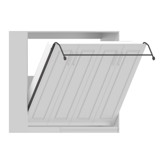
- Page 29 Chapter 5: Attaching the Bed Face Panel to the Bed Cabinet. For video instructions of this specific chapter, visit: breda.us/face FIG. 5C - LOOKING THROUGH LEFT SIDE FIG. 5D - LOOKING THROUGH LEFT SIDE 1. Referring to Fig. 5C, stand the Bed Face Panel in vertical position between the mechanism arms, lifting until the bolt in STEP 4 Hole #3 drops in the slotted portion of each mechanism arm.
-
Page 30: Chapter 6: Installing The Handles, Leg Support And Mattress
Chapter 6: Installing the handles, leg support and mattress. Chapter 6: Installing the handles, leg support and mattress. REQUIRED TOOLS REQUIRED HARDWARE • Cordless Drill w/ bit holder • Hardware Package #4 • #2 Phillips bit • Hardware Package #5 (Optional) •... - Page 31 Chapter 6: Installing the handles, leg support and mattress. FIG. 6B - LEG AND CONNECTOR ROD, LEFT SIDE STEP 3 Install the leg connector rod between the legs and secure with 1/4”-20 x 1 1/4” Hex head bolts and star washers from Hardware Package #4 and securely tighten...
-
Page 32: Chapter 7: Final Adjustment For The Bed Cabinet And Springs
Hard Surface (tile, wood, etc): Attach with the wider (~1”) side down so the bottom of the Toe Kick is flush with the rest of the Murphy Bed. • Carpet: Attach with the narrow (~3/4”) side down to give room under the Toe Kick. - Page 33 Chapter 7: Final adjustment for the Bed Cabinet and springs. To determine the proper tension, the mattress needs to be in place. The face assembly should raise and lower with about STEP 3 10 pounds of pressure and bed legs should rest on the floor without lifting when bed is open.
-
Page 34: Chapter 8: How To Disassemble The Bed For Moving
Chapter 8: How to disassemble the bed for moving. Chapter 8: How to disassemble the bed for moving. REQUIRED TOOLS ESTIMATED TIME • Cordless Drill with #2 Phillips 30 Minutes • 1/2 Wrench or Adjustable Pliers Note: This is an average time only, yours may vary.
Need help?
Do you have a question about the MURPHY and is the answer not in the manual?
Questions and answers