Table of Contents
Advertisement
Industrial Automation Headquarters
Taiwan:
Delta Electronics, Inc.
Taoyuan Technology Center
No.18, Xinglong Rd., Taoyuan District,
Taoyuan City 33068, Taiwan
TEL: +886-3-362-6301 / FAX: +886-3-371-6301
Asia
China:
Delta Electronics ( Shanghai ) Co., Ltd.
No.182 Minyu Rd., Pudong Shanghai, P.R.C.
Post code : 201209
TEL: +86-21-6872-3988 / FAX: +86-21-6872-3996
Customer Service: 400-820-9595
Delta Electronics ( Japan ) , Inc.
Japan:
Industrial Automation Sales Department
2-1-14 Shibadaimon, Minato-ku
Tokyo, Japan 105-0012
TEL: +81-3-5733-1155 / FAX: +81-3-5733-1255
Delta Electronics ( Korea ) , Inc.
Korea:
1511, 219, Gasan Digital 1-Ro., Geumcheon-gu,
Seoul, 08501 South Korea
TEL: +82-2-515-5305 / FAX: +82-2-515-5302
Delta Energy Systems ( Singapore ) Pte Ltd.
Singapore:
4 Kaki Bukit Avenue 1, #05-04, Singapore 417939
TEL: +65-6747-5155 / FAX: +65-6744-9228
Delta Electronics ( India ) Pvt. Ltd.
India:
Plot No.43, Sector 35, HSIIDC Gurgaon,
PIN 122001, Haryana, India
TEL: +91-124-4874900 / FAX: +91-124-4874945
Delta Electronics ( Thailand ) PCL.
Thailand:
909 Soi 9, Moo 4, Bangpoo Industrial Estate ( E.P.Z ) ,
Pattana 1 Rd., T.Phraksa, A.Muang,
Samutprakarn 10280, Thailand
TEL: +66-2709-2800 / FAX: +66-2709-2827
Delta Electronics ( Australia ) Pty Ltd.
Australia:
Unit 2, Building A, 18-24 Ricketts Road,
Mount Waverley, Victoria 3149 Australia
Mail: IA.au@deltaww.com
TEL: +61-1300-335-823 / +61-3-9543-3720
Americas
Delta Electronics ( Americas ) Ltd.
USA:
5101 Davis Drive, Research Triangle Park, NC 27709, U.S.A.
TEL: +1-919-767-3813 / FAX: +1-919-767-3969
Brazil:
Delta Electronics Brazil Ltd.
Estrada Velha Rio-São Paulo, 5300 Eugênio de
Melo - São José dos Campos CEP: 12247-004 - SP - Brazil
TEL: +55-12-3932-2300 / FAX: +55-12-3932-237
Mexico:
Delta Electronics International Mexico S.A. de C.V.
Gustavo Baz No. 309 Edificio E PB 103
Colonia La Loma, CP 54060
Tlalnepantla, Estado de México
TEL: +52-55-3603-9200
*We reserve the right to change the information in this manual without prior notice.
DELTA_IA-MDS_C2000 Plus_UM_EN_20220831
EMEA
EMEA Headquarters:
Delta Electronics ( Netherlands ) B.V.
Sales: Sales.IA.EMEA@deltaww.com
Marketing: Marketing.IA.EMEA@deltaww.com
Technical Support: iatechnicalsupport@deltaww.com
Customer Support: Customer-Support@deltaww.com
Service: Service.IA.emea@deltaww.com
TEL: +31 ( 0 ) 40 800 3900
BENELUX:
Delta Electronics ( Netherlands ) B.V.
Automotive Campus 260, 5708 JZ Helmond, The Netherlands
Mail: Sales.IA.Benelux@deltaww.com
TEL: +31 ( 0 ) 40 800 3900
DACH:
Delta Electronics ( Netherlands ) B.V.
Coesterweg 45, D-59494 Soest, Germany
Mail: Sales.IA.DACH@deltaww.com
TEL: +49 ( 0 ) 2921 987 0
Delta Electronics ( France ) S.A.
France:
ZI du bois Challand 2, 15 rue des Pyrénées,
Lisses, 91090 Evry Cedex, France
Mail: Sales.IA.FR@deltaww.com
TEL: +33 ( 0 ) 1 69 77 82 60
Iberia:
Delta Electronics Solutions ( Spain ) S.L.U
Ctra. De Villaverde a Vallecas, 265 1º Dcha Ed.
Hormigueras – P.I. de Vallecas 28031 Madrid
TEL: +34 ( 0 ) 91 223 74 20
Carrer Llacuna 166, 08018 Barcelona, Spain
Mail: Sales.IA.Iberia@deltaww.com
Delta Electronics ( Italy ) S.r.l.
Italy:
Via Meda 2–22060 Novedrate ( CO )
Piazza Grazioli 18 00186 Roma Italy
Mail: Sales.IA.Italy@deltaww.com
TEL: +39 039 8900365
Russia:
Delta Energy System LLC
Vereyskaya Plaza II, office 112 Vereyskaya str.
17 121357 Moscow Russia
Mail: Sales.IA.RU@deltaww.com
TEL: +7 495 644 3240
Delta Greentech Elektronik San. Ltd. Sti. ( Turkey )
Turkey:
Şerifali Mah. Hendem Cad. Kule Sok. No:16-A
34775 Ümraniye – İstanbul
Mail: Sales.IA.Turkey@deltaww.com
TEL: + 90 216 499 9910
MEA:
Eltek Dubai ( Eltek MEA DMCC )
OFFICE 2504, 25th Floor, Saba Tower 1,
Jumeirah Lakes Towers, Dubai, UAE
Mail: Sales.IA.MEA@deltaww.com
TEL: +971 ( 0 ) 4 2690148
Delta High Performance
Vector Control Drive
C2000 Plus Series
User Manual
w w w. d e l t a w w. c o m
Advertisement
Table of Contents

Related Manuals for Delta C2000 Plus Series


Summary of Contents for Delta C2000 Plus Series
- Page 1 Mail: Sales.IA.RU@deltaww.com TEL: +7 495 644 3240 Delta Electronics ( Americas ) Ltd. USA: Delta Greentech Elektronik San. Ltd. Sti. ( Turkey ) 5101 Davis Drive, Research Triangle Park, NC 27709, U.S.A. Turkey: TEL: +1-919-767-3813 / FAX: +1-919-767-3969 Şerifali Mah. Hendem Cad. Kule Sok. No:16-A 34775 Ümraniye –...
- Page 2 All information contained in this user manual is the exclusive property of Delta Electronics Inc. (hereinafter referred to as "Delta ") and is protected by copyright law and all other laws. Delta retains the exclusive rights of this user manual in accordance with the copyright law and all other laws. No parts in this manual may be reproduced, transmitted, transcribed, translated or used in any other ways without the prior consent of Delta.
- Page 4 PLEASE READ PRIOR TO INSTALLATION FOR SAFETY. Disconnect AC input power before connecting any wiring to the AC motor drive. Even if the power has been turned off, a charge may still remain in the DC-link capacitors with hazardous voltages before the POWER LED is OFF. Do NOT touch the internal circuits and components.
- Page 5 2. Use other methods, such as heat treatment or any other non-fumigation treatment, to deworm the wood packaging material. 3. If you use heat treatment to deworm, leave the packaging materials in an environment of over 56°C for a minimum of thirty minutes. ...
-
Page 6: Table Of Contents
Table of Contents CHAPTER 1 INTRODUCTION ........................1-1 1-1 Nameplate Information…....................1-2 1-2 Model Name………….......................1-3 1-3 Serial Number.........................1-4 1-4 Apply After Service by Mobile Device…………………………………………………………...……1-5 1-5 RFI Jumper…........................1-6 1-6 Dimensions........................1-9 CHAPTER 2 INSTALLATION ........................2-1 2-1 Mounting Clearance......................2-2 2-2 Airflow and Power Dissipation..................2-5 CHAPTER 3 UNPACKING ........................ - Page 7 8-17 CMC-PN01 ..........8-51 -- Communication card, PROFINET 8-18 EMC-COP01 ..........8-55 -- Communication card, CANopen 8-19 Delta Standard Fieldbus Cables…………………………………………………………8-56 CHAPTER 9 SPECIFICATION ........................9-1 9-1 230V Models…………………………………................9-2 9-2 460V Models…………………………………................9-3 9-3 575V Models……………………………………………………………………………………...…9-6 9-4 690V Models…………………………………………………………………………………………9-7 9-5 Environment for Operation, Storage and Transportation………………………….....9-12 9-6 Specification for Operation Temperature and Protection Level……........9-13...
- Page 8 02 Digital Input / Output Parameters………………………………………………………….12.1-02-1 03 Analog Input / Output Parameters………………………………………………………12.1-03-1 04 Multi-step Speed Parameters………………………………………………………. ….12.1-04-1 05 Motor Parameters……………………………………………………………………….….12.1-05-1 06 Protection Parameters…………………………………………………………………….12.1-06-1 07 Special Parameters……………………………………………………………………….12.1-07-1 08 High-function PID Parameters…………………………………………………………….12.1-08-1 09 Communication Parameters………………………………………………………….……12.1-09-1 10 Feedback Control Parameters……………………………………………………………12.1-10-1 11 Advanced Parameters………………………………………………………………….…12.1-11-1 13 Application Parameters by Industry…………………………………………………….12.1-13-1 14 Extension Card Parameter……………………………….…………………………….12.1-14-1 12-2 Adjustment &...
- Page 9 17-4 Parameters……………………………………………………………………………………………17-6 17-5 Operating Sequence Description…………………………………………………...………………17-7 17-6 New Error Code for STO Function……………………………………………………….……….17-9 APPENDIX A. REVISION HISTORY…………………………………………………..………………………..A-1 A-1 Code Description………………………..……………………………………………………………A-2 A-2 Data Format……………………………..……………………………………………………………A-2 A-3 Communication Protocol…………..……………………………………………………………A-3 A-4 Address List……………………..………………………………..………………………………A-8 APPENDIX B. REVISION HISTORY…………………………………………………..………………………..B-1 Issued Edition: 02 Firmware Version: V3.07 (Refer to Parameter 00-06 on the product to get the firmware version.) Issued Date: 2022 / 08 VIII...
-
Page 10: Chapter 1 Introduction
Chapter 1 IntroductionC2000 Plus Chapter 1 Introduction Nameplate Information Model Name Serial Number Apply After Service by Mobile Device RFI Jumper Dimensions... -
Page 11: Nameplate Information
Chapter 1 IntroductionC2000 Plus After receiving the AC motor drive, please check for the following: Inspect the unit after unpacking to ensure that it was not damaged during shipment. Make sure that the part number printed on the package matches the part number indicated on the nameplate. Make sure that the mains voltage is within the range indicated on the nameplate. -
Page 12: Model Name
Chapter 1 IntroductionC2000 Plus 1-2 Model Name... -
Page 13: Serial Number
Chapter 1 IntroductionC2000 Plus 1-3 Serial Number... -
Page 14: Apply After Service By Mobile Device
2. Using a Smartphone to run a QR Code reader APP. 3. Point your camera to the QR Code. Hold your camera steady so that the QR code comes into focus. 4. Access the Delta after Service website. 5. Fill your information into the column marked with an orange star. -
Page 15: Rfi Jumper
Chapter 1 IntroductionC2000 Plus 1-5 RFI Jumper (1) The drive contains Varistors / MOVs that are connected from phase to phase and from phase to ground to prevent the drive from unexpected stop or damage caused by mains surges or voltage spikes. - Page 16 Chapter 1 IntroductionC2000 Plus Isolating main power from ground: When the power distribution system of the drive is a floating ground system (IT Systems) or an asymmetric ground system (Corner Grounded TN Systems), you must remove the RFI jumper. Removing the RFI jumper disconnects the internal capacitors from ground to avoid damaging the internal circuits and to reduce the ground leakage current.
- Page 17 Chapter 1 IntroductionC2000 Plus Asymmetric Ground System (Corner Grounded TN Systems) Caution: Do not remove the RFI jumper while power to the input terminal of the drive is ON. In the following four situations, the RFI jumper must be removed. This is to prevent the system from grounding through the RFI and filter capacitor and damaging the drive.
-
Page 18: Dimensions
Chapter 1 IntroductionC2000 Plus 1-6 Dimensions Frame A VFD007C23A-21; VFD007C43A-21; VFD007C4EA-21; VFD015C23A-21; VFD015C43A-21; VFD015C4EA-21; VFD015C53A-21; VFD022C23A-21; VFD022C43A-21; VFD022C4EA-21; VFD022C53A-21; VFD037C23A-21; VFD037C43A-21; VFD037C4EA-21; VFD037C53A-21; VFD040C43A-21; VFD040C4EA-21; VFD055C43A-21; VFD055C4EA-21 See Detail A See Detail B Detail A (Mounting Hole) Detail B (Mounting Hole) Figure 1-15 Unit: mm [inch] Φ1... - Page 19 Chapter 1 IntroductionC2000 Plus Frame B VFD055C23A-21; VFD055C53A-21; VFD075C23A-21; VFD075C43A-21; VFD075C4EA-21; VFD075C53A-21; VFD110C23A-21; VFD110C43A-21; VFD110C4EA-21; VFD110C53A-21; VFD150C43A-21; VFD150C4EA-21; VFD150C53A-21 See Detail A See Detail A See Detail B See Detail B Detail A (Mounting Hole) Detail A (Mounting Hole) Detail B (Mounting Hole) Detail B (Mounting Hole) Figure 1-16 Unit: mm [inch]...
- Page 20 Chapter 1 IntroductionC2000 Plus Frame C VFD150C23A-21; VFD185C23A-21; VFD185C43A-21; VFD185C4EA-21; VFD185C63B-21; VFD220C23A-21; VFD220C43A-21; VFD220C4EA-21; VFD220C63B-21; VFD300C43A-21; VFD300C4EA-21; VFD300C63B-21; VFD370C63B-21 See Detail A See Detail B See Detail B Detail A (Mounting Hole) Detail A (Mounting Hole) Detail B (Mounting Hole) Detail B (Mounting Hole) Figure 1-17 Unit: mm [inch]...
- Page 21 Chapter 1 IntroductionC2000 Plus Frame D0 D0-1: VFD370C43S-00; VFD450C43S-00 See Detail A SEE DETAIL A See Detail B SEE DETAIL B Detail A Detail B DETAIL A DETAIL B (MOUNTING HOLE) (MOUNTING HOLE) (Mounting Hole) (Mounting Hole) Figure 1-18 Unit: mm [inch] Frame 280.0 500.0...
- Page 22 Chapter 1 IntroductionC2000 Plus Frame D0 D0-2: VFD370C43S-21; VFD450C43S-21 See Detail A SEE DETAIL A See Detail B SEE DETAIL B Detail A Detail B DETAIL A DETAIL B (MOUNTING HOLE) (MOUNTING HOLE) (Mounting Hole) (Mounting Hole) Figure 1-19 Unit: mm [inch] Φ1 Φ2 Φ3...
- Page 23 Chapter 1 IntroductionC2000 Plus Frame D D1: VFD300C23A-00; VFD370C23A-00; VFD450C63B-00; VFD550C43A-00; VFD550C63B-00; VFD750C43A-00 See Detail A SEE DETAIL A See Detail B SEE DETAIL B Detail A Detail B DETAIL A DETAIL B (MOUNTING HOLE) (MOUNTING HOLE) (Mounting Hole) (Mounting Hole) Figure 1-20 Unit: mm [inch] Φ1...
- Page 24 Chapter 1 IntroductionC2000 Plus Frame D D2: VFD300C23A-21; VFD370C23A-21; VFD450C63B-21; VFD550C43A-21; VFD550C63B-21; VFD750C43A-21 See Detail A SEE DETAIL A See Detail B SEE DETAIL B Detail A Detail B DETAIL A DETAIL B (MOUNTING HOLE) (MOUNTING HOLE) (Mounting Hole) (Mounting Hole) Figure 1-21 Unit: mm [inch] Φ1...
- Page 25 Chapter 1 IntroductionC2000 Plus Frame E E1: VFD450C23A-00; VFD550C23A-00; VFD750C23A-00; VFD750C63B-00; VFD900C43A-00; VFD900C63B-00; VFD1100C43A-00; VFD1100C63B-00; VFD1320C63B-00 See Detail A See Detail B Detail A Detail B (Mounting Hole) (Mounting Hole) Figure 1-22 Unit: mm [inch] Ф1 Ф2 Ф3 Frame S1, S2 370.0 300.0 335.0...
- Page 26 Chapter 1 IntroductionC2000 Plus Frame E E2: VFD450C23A-21; VFD550C23A-21; VFD750C23A-21; VFD750C63B-21; VFD900C43A-21; VFD900C63B-21; VFD1100C43A-21; VFD1100C63B-21; VFD1320C63B-21 See Detail A See Detail B Detail A Detail B (Mounting Hole) (Mounting Hole) Figure 1-23 Unit: mm [inch] Ф1 Ф2 Ф3 Frame S1, S2 370.0 715.8 300.0...
- Page 27 Chapter 1 IntroductionC2000 Plus Frame F F1: VFD900C23A-00; VFD1320C43A-00; VFD1600C43A-00; VFD1600C63B-00; VFD2000C63B-00 See Detail A See Detail A See Detail B See Detail B Detail A (Mounting Hole) Detail A (Mounting Hole) Detail B (Mounting Hole) Detail B (Mounting Hole) Figure 1-24 Unit: mm [inch] Frame...
- Page 28 Chapter 1 IntroductionC2000 Plus Frame F F2: VFD900C23A-21; VFD1320C43A-21; VFD1600C43A-21; VFD1600C63B-21; VFD2000C63B-21 See Detail A See Detail A See Detail B See Detail B Detail A (Mounting Hole) Detail A (Mounting Hole) Detail B (Mounting Hole) Detail B (Mounting Hole) Figure 1-25 Unit: mm [inch] Frame...
- Page 29 Chapter 1 IntroductionC2000 Plus Frame G G1: VFD1850C43A-00; VFD2000C43A-00; VFD2200C43A-00; VFD2500C43A-00; VFD2500C63B-00; VFD3150C63B-00 See Detail A See Detail B Detail A Detail B (Mounting Hole) (Mounting Hole) Figure 1-26 Unit: mm [inch] Ф1 Ф2 Ф3 Frame 500.0 397.0 440.0 1000.0 963.0 913.6 13.0...
- Page 30 Chapter 1 IntroductionC2000 Plus Frame G G2: VFD1850C43A-21; VFD2000C43A-21; VFD2200C43A-21; VFD2500C43A-21; VFD2500C63B-21; VFD3150C63B-21 See Detail A See Detail B Detail A Detail B (Mounting Hole) (Mounting Hole) Figure 1-27 Unit: mm [inch] Ф1 Ф2 Ф3 Frame 500.0 1240.2 397.0 440.0 1000.0 963.0 913.6...
- Page 31 Chapter 1 IntroductionC2000 Plus Frame H H1: VFD2800C43A-00; VFD3150C43A-00; VFD3550C43A-00; VFD4000C43A-00; VFD4000C63B-00; VFD4500C43A-00; VFD4500C63B-00; VFD5000C43A-00; VFD5600C43A-00; VFD5600C63B-00; VFD6300C63B-00 See Detail A See Detail B Detail A Detail B (Mounting Hole) (Mounting Hole) Figure 1-28 Unit: mm [inch] Frame 700.0 1435.0 398.0 630.0 290.0...
- Page 32 Chapter 1 IntroductionC2000 Plus Frame H H3: VFD2800C43C-21; VFD3150C43C-21; VFD3550C43C-21; VFD4000C43C-21; VFD4500C43C-21; VFD5000C43C-21; VFD5600C43C-21 See Detail A Side fixing Side fixing baffle plate 側邊固定件 側邊固定件 baffle plate See Detail B Detail A Detail B (Mounting Hole) (Mounting Hole) Figure 1-29 Unit: mm [inch] Frame 700.0...
- Page 33 Chapter 1 IntroductionC2000 Plus 690V Frame H H2: VFD4000C63B-21; VFD4500C63B-21; VFD5600C63B-21; VFD6300C63B-21 See Detail A See Detail A See Detail B See Detail B Side fixing Side fixing baffle plate 側邊固定件 側邊固定件 baffle plate See Detail C See Detail C Detail C Detail C (Mounting (Mounting hole)
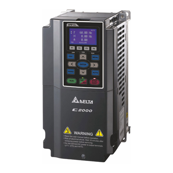
- Page 34 Chapter 1 IntroductionC2000 Plus Digital Keypad KPC-CC01 Figure 1-31 1-25...
- Page 35 Chapter 1 IntroductionC2000 Plus [This page intentionally left blank] 1-26...
-
Page 36: Chapter 2 Installation
Chapter 2 InstallationC2000 Plus Chapter 2 Installation Mounting Clearance Airflow and Power Dissipation... -
Page 37: Mounting Clearance
Chapter 2 InstallationC2000 Plus 2-1 Mounting Clearance Prevent fiber particles, scraps of paper, shredded wood, sawdust, metal particles, etc. from adhering to the heat sink. Install the AC motor drive in a metal cabinet. When installing one drive below another one, use a metal separator between the AC motor drives to prevent mutual heating and to prevent the risk of fire accident. - Page 38 Chapter 2 InstallationC2000 Plus Multiple drives side-by-side vertical installation Ta: Frame A–G Ta*: Frame H When installing one AC motor drive below another one (top-bottom installation), use a metal separator between the drives to prevent mutual heating. The temperature measured at the fan’s inflow side must be lower than the temperature measured at the operation side.
- Page 39 Chapter 2 InstallationC2000 Plus VFD007C23A-21; VFD007C43A-21; VFD007C4EA-21; VFD015C23A-21; VFD015C43A-21; VFD015C4EA-21; VFD015C53A-21; VFD022C23A-21; VFD022C43A-21; VFD022C4EA-21; Frame A VFD022C53A-21; VFD037C23A-21; VFD037C43A-21; VFD037C4EA-21; VFD037C53A-21; VFD040C43A-21; VFD040C4EA-21; VFD055C43A-21; VFD055C4EA-21 VFD055C23A-21; VFD055C53A-21; VFD075C23A-21; VFD075C43A-21; VFD075C4EA-21; Frame B VFD075C53A-21; VFD110C23A-21; VFD110C43A-21; VFD110C4EA-21; VFD110C53A-21; VFD150C43A-21; VFD150C4EA-21; VFD150C53A-21 VFD150C23A-21;...
-
Page 40: Airflow And Power Dissipation
Chapter 2 InstallationC2000 Plus 2-2 Airflow and Power Dissipation Power Dissipation for Airflow Rate for Cooling AC Motor Drive Model No. Flow Rate (Unit: cfm) Flow Rate (Unit: m / hr) Power Dissipation (Unit: watt) Loss External External Internal Total External Internal Total Internal... - Page 41 Chapter 2 InstallationC2000 Plus Power Dissipation for Airflow Rate for Cooling AC Motor Drive Model No. Flow Rate (Unit: cfm) Flow Rate (Unit: m / hr) Power Dissipation (Unit: watt) Loss External External Internal Total External Internal Total Internal Total (Heat sink) VFD900C43A-00 1693...
- Page 42 Chapter 2 InstallationC2000 Plus Power Dissipation for Airflow Rate for Cooling AC Motor Drive Model No. Flow Rate (Unit: cfm) Flow Rate (Unit: m / hr) Power Dissipation (Unit: watt) Loss External External Internal Total External Internal Total Internal Total (Heat sink) VFD2000C63B-00 248.1...
- Page 43 Chapter 2 InstallationC2000 Plus [This page intentionally left blank]...
-
Page 44: Chapter 3 Unpacking
Chapter 3 UnpackingC2000 Plus Chapter 3 Unpacking Unpacking The Lifting Hook... -
Page 45: Unpacking
Chapter 3 UnpackingC2000 Plus The AC motor drive should be kept in the shipping carton or crate before installation. In order to retain the warranty coverage, the AC motor drive should be stored properly when it is not to be used for an extended period of time. - Page 46 Chapter 3 UnpackingC2000 Plus Loosen the eight screws fasten the drive on the Loosen the ten screws fasten the drive on the pallet, and then remove the wood plate. pallet, and then remove the wood plates and the conduit box. Figure 3-3 Figure 3-7 Lift the drive by hooking the lifting hole.
- Page 47 Chapter 3 UnpackingC2000 Plus Frame F Unpacking 1 Unpacking 2 (VFDXXXCXXA-00, VFDXXXC63B-00) (VFDXXXCXXA-21, VFDXXXC63B-21) Remove the six buckles fixed on the crate with a Remove the six buckles fixed on the crate with a flat-head screwdriver, see the figure below. flat-head screwdriver, see the figure below.
- Page 48 Chapter 3 UnpackingC2000 Plus Loosen the five screws fasten the drive on the Loosen the five screws fasten the drive on the pallet, see the figure below. pallet, and then remove the wood plates and conduit box. Figure 3-11 Figure 3-15 Lift the drive by hooking the lifting hole.
- Page 49 Chapter 3 UnpackingC2000 Plus Frame G Unpacking 1 Unpacking 2 (VFDXXXCXXA-00, VFDXXXC63B-00) (VFDXXXCXXA-21, VFDXXXC63B-21) Remove the six buckles fixed on the crate with a Remove the six buckles fixed on the crate with a flat-head screwdriver, see the figure below. flat-head screwdriver, see the figure below.
- Page 50 Chapter 3 UnpackingC2000 Plus Loosen the five screws fasten the drive on the Loosen the 12 screws fasten the drive on the pallet, see the figure below. pallet, and then remove the wood plates and conduit box. Figure 3-19 Figure 3-23 Lift the drive by hooking the lifting hole.
- Page 51 Chapter 3 UnpackingC2000 Plus Frame H Unpacking 1 (VFDXXXC43A-00) Remove the eight buckles fixed on the crate with a flat-head screwdriver, see the figure below. Figure 3-25 Remove the top cover, take out the EPEs and the manual. Figure 3-26 Loosen the six screws fasten the drive on the pallet, and then remove six metal washers and six plastic washers.
- Page 52 Chapter 3 UnpackingC2000 Plus Lift the drive by hooking the lifting hole. It is now ready for installation. Figure 3-28 Unpacking 2 (VFDXXXC43C-21) Remove the eight buckles fixed on the crate with a flat-head screwdriver, see the figure below. Figure 3-29 Remove the cover, take out the EPEs and the manual.
- Page 53 Chapter 3 UnpackingC2000 Plus Loosen the six screws fasten the drive on the pallet, and then remove six metal washers and six plastic washers. See the figure below. Figure 3-31 Loosen the six M6 screws and the iron plates (see the figure below). You can use the removed screws and iron plates to fix the drive from outside.
- Page 54 Chapter 3 UnpackingC2000 Plus Fix the drive from the inside Fix the drive from the outside Loosen the 18 M6 screws and remove the covers Loosen the eight M8 screws, and then use (see the figure 3-34). After fixing the drive and the these eight M8 screws to fix the iron plates cover for cables (see the figure 3-33), fasten the (removed at the last step) to the drive, see the...
- Page 55 Chapter 3 UnpackingC2000 Plus Lift the drive by hooking the lifting hole. It is now ready for installation. Figure 3-38 3-12...
- Page 56 Chapter 3 UnpackingC2000 Plus 690V Frame H Unpacking 1 (VFDXXXC63B-00) Remove the eight buckles fixed on the crate with a flat-head screwdriver, see the figure below. Figure 3-39 Remove the top cover, take out the EPEs and the manual. Figure 3-40 Loosen the six screws fasten the drive on the pallet, and then remove six metal washers and six plastic washers.
- Page 57 Chapter 3 UnpackingC2000 Plus Lift the drive by hooking the lifting hole. It is now ready for installation. Figure 3-42 Unpacking 2 (VFDXXXC63B-21) Remove the eight buckles fixed on the crate with a flat-head screwdriver, see the figure below. Figure 3-43 Remove the top cover, take out the EPEs, rubber and the manual.
- Page 58 Chapter 3 UnpackingC2000 Plus Loosen the six screws fasten the drive on the pallet, and then remove six metal washers and six plastic washers. See the figure below. Figure 3-45 Loosen the six M6 screws and the iron plates (see the figure below). You can use the removed screws and iron plates to fix the drive from the outside.
- Page 59 Chapter 3 UnpackingC2000 Plus Fix the drive from the inside Fix the drive from the outside Loosen the 18 M6 screws and remove the covers Loosen the eight M8 screws, and then use (see the figure 3-48). After fixing the drive and the these eight M8 screws to fix the iron plates cover for cables (see figure 3-47), fasten the other (removed at the last step) to the drive, see the...
- Page 60 Chapter 3 UnpackingC2000 Plus Lift the drive by hooking the lifting hole. It is now ready for installation. Figure 3-52 3-17...
- Page 61 Chapter 3 UnpackingC2000 Plus Frame H: Fix the drive VFDXXXC43A-00 Screw: M12*6 Torque: 340–420 kg-cm / (295.1–364.6 lb-in.) / (33.3–41.2 Nm) Figure 3-53 VFDXXXC43C-21 Fix the drive from the inside. Screw: M12*8 Torque: 340–420 kg-cm / (295.1–364.6 lb-in.) / (33.3–41.2 Nm) Figure 3-54 3-18...
- Page 62 Chapter 3 UnpackingC2000 Plus Fix the drive from the outside. Screw: M12*8 Torque: 340–420 kg-cm / (295.1–364.6 lb-in.) / (33.3–41.2 Nm) Figure 3-55 VFDXXXC63B Screw M 12*6 Torque: 340–420 kg-cm / (295.1–364.6 lb-in.) / 33.32–41.16 Nm) Figure 3-56 3-19...
- Page 63 Chapter 3 UnpackingC2000 Plus VFDXXXC63B-21 Fix the drive from the outside. Screw: M12*8 Torque: 340–420 kg-cm / (295.1–364.6 lb-in.) / (33.32–41.16 Nm) Figure 3-57 3-20...
-
Page 64: The Lifting Hook
Chapter 3 UnpackingC2000 Plus 3-2 The Lifting Hook The arrows indicate the location of the lifting holes of frame D to H, as shown in figure below: Frame D0 Applicable models: VFD370C43S-00; VFD370C43S-21; VFD450C43S-00; VFD450C43S-21 Figure 3-58 Frame D Applicable models: VFD300C23A-00;... -
Page 65: Vfd900C23A-00; Vfd900C23A-21; Vfd1320C43A-00; Vfd1320C43A-21; Vfd1600C43A-00; Vfd1600C43A-21; Vfd1600C63B-00; Vfd1600C63B-21; Vfd2000C63B-00; Vfd2000C63B-21
Chapter 3 UnpackingC2000 Plus Frame F Applicable models: VFD900C23A-00; VFD900C23A-21; VFD1320C43A-00; VFD1320C43A-21; VFD1600C43A-00; VFD1600C43A-21; VFD1600C63B-00; VFD1600C63B-21; VFD2000C63B-00; VFD2000C63B-21 Figure 3-61 Frame G Applicable models: VFD1850C43A-00; VFD1850C43A-21; VFD2000C43A-00; VFD2000C43A-21; VFD2200C43A-00; VFD2200C43A-21; VFD2500C43A-00; VFD2500C43A-21; VFD2500C63B-00; VFD2500C63B-21; VFD3150C63B-00; VFD3150C63B-21 Figure 3-62 Frame H Applicable models: VFD2800C43A-00;... -
Page 66: Figure
Chapter 3 UnpackingC2000 Plus 690V Frame H3 Applicable models: VFD4000C63B-21; VFD4500C63B-21; VFD5600C63B-21; VFD6300C63B-21 Figure 3-64 3-23... - Page 67 Chapter 3 UnpackingC2000 Plus Ensure the lifting hook properly goes through the Ensure the angle between the lifting holes and the lifting hole, as shown in the following diagram. lifting device is within the specification, as shown in the following figure. Applicable to Frame D0–E Applicable to Frame D0–E Figure 3-65...
- Page 68 Chapter 3 UnpackingC2000 Plus Weight VFDXXXXCXXS-00: 27 kg / (59.5 lbs) VFDXXXXCXXS-21: 29 kg / (63.9 lbs) Figure 3-69 Figure 3-70 VFDXXXXCXXA-00: 37.6 kg / (82.9 lbs) VFDXXXXCXXA-21: 40 kg / (88.2 lbs) VFDXXXC63B-00: 39.0 kg / (86.0 lbs) VFDXXXC63B-21: 41.1 kg / (91.3 lbs) Figure 3-71 Figure 3-72 VFDXXXXCXXA-00: 63.6 kg / (140.2 lbs)
- Page 69 Chapter 3 UnpackingC2000 Plus VFD2800C43A-00; VFD3150C43A-00; VFD3550C43A-00; VFD4000C43A-00; VFD4500C43A-00: 244 kg / (537.9 lbs) VFD5000C43A-00; VFD5600C43A-00: 270 kg / (595.2 lbs) VFDXXXC63B-00: 243.0 kg / (535.7 lbs) Figure 3-79 VFDXXXC63B-21: 251.0 kg / (553.5 lbs) Figure 3-80 VFD2800C43C-21; VFD3150C43C-21; VFD3550C43C-21; VFD4000C43C-21; VFD4500C43C-21: 269 kg / (593.0 lbs) VFD5000C43C-21;...
-
Page 70: Chapter 4 Wiring
Chapter 4 WiringC2000 Plus Chapter 4 Wiring System Wiring Diagram Wiring... - Page 71 Chapter 4 WiringC2000 Plus After removing the front cover, verify that the power and control terminals are clearly noted. Read the following precautions before wiring. Turn off the AC motor drive power before doing any wiring. A charge with hazardous voltages may remain in the DC bus capacitors even after the power has been turned off for a short time.
-
Page 72: System Wiring Diagram
Chapter 4 WiringC2000 Plus 4-1 System Wiring Diagram Supply power according to the rated power Power input specifications indicated in the manual (refer to terminal Chapter 9 Specification). There may be a large inrush current during power on. Refer to Section 7-2 NFB to select NFB or fuse a suitable NFB or Section 7-3 Fuse Specification Chart. -
Page 73: Wiring
Chapter 4 WiringC2000 Plus 4-2 Wiring 4-2-1 Wiring Figure 4-2 Figure 4-3 NOTE: *1 means that refer to Section 7-1 for brake units and resistors selection. - Page 74 Chapter 4 WiringC2000 Plus Figure 4-4 Figure 4-5 NOTE: 1. *1 means that refer to Section 7-1 for brake units and resistors selection. 2. When wiring for 12 Pulse Input, strictly follow above wiring diagram.
- Page 75 Chapter 4 WiringC2000 Plus MODBUS RS-485 Figure 4-6...
- Page 76 Chapter 4 WiringC2000 Plus 4-2-2 SINK (NPN) / SOURCE (PNP) Mode Figure 4-7 Figure 4-8 Figure 4-9 Figure 4-10...
- Page 77 Chapter 4 WiringC2000 Plus [This page intentionally left blank]...
-
Page 78: Chapter 5 Main Circuit Terminals
Chapter 5 Main Circuit TerminalsC2000 Plus Chapter 5 Main Circuit Terminals Main Circuit Diagram Main Circuit Terminals... - Page 79 If necessary, use an inductive filter only at the motor output terminals U/T1, V/T2, W/T3 of the AC motor drive. DO NOT use phase-compensation capacitors or L-C (Inductance-Capacitance) or R-C (Resistance-Capacitance), unless approved by Delta. DO NOT connect phase-compensation capacitors or surge absorbers at the output terminals of AC motor drives.
- Page 80 Chapter 5 Main Circuit TerminalsC2000 Plus Terminals for connecting DC reactor, external brake resistor and DC circuit Use the terminals, as shown in Figure 5-2, to connect a DC reactor to improve the power factor and reduce harmonics. A jumper is connected to these terminals at the factory.
-
Page 81: Main Circuit Diagram
Chapter 5 Main Circuit TerminalsC2000 Plus 5-1 Main Circuit Diagram Figure 5-4 Figure 5-5 Figure 5-6... - Page 82 3. Frame G and H models use 12 pulse input, you should remove the short circuit plate (see the figure below). Consult with Delta before using 12 pulse input. 4. When wiring for 12 pulse input, strictly follow above wiring diagram.
- Page 83 Chapter 5 Main Circuit TerminalsC2000 Plus Tighten the screw after the short circuit plate is removed. Screw torque: 100–110 kg-cm / (86.8–95.5 lb-in.) / (9.8–10.8 Nm) Detail A Detail A Figure 5-9 Terminals Descriptions R/L1, S/L2, T/L3 Mains input terminals (three-phase) U/T1, V/T2, W/T3 AC motor drive output terminals for connecting three-phase induction motor Applicable to frame A–C...
-
Page 84: Main Circuit Terminal Specifications
Chapter 5 Main Circuit TerminalsC2000 Plus 5-2 Main Circuit Terminal Specifications Use the specified ring lug for main circuit terminal wiring. See figure 5-10 and figure 5-11 for ring lug specifications. For other types of wiring, use the wires that comply with the local regulations. ... - Page 85 Chapter 5 Main Circuit TerminalsC2000 Plus Frame Kit P/N (MAX) (MAX) (MIN) (MAX) (MIN) (MIN) (MIN) (MAX) (MAX) RNB60-8 RNB70-8 53.0 16.0 17.0 26.5 13.0 17.0 31.0 RNB80-8 RNB100-8 RNB80-8 SQNBS100-8 55.0 15.0 10.0 27.0 13.0 17.5 31.0 300MCM SQNBS150-8 SQNBS60-8 SQNBS80-8 SQNBS80-8...
- Page 86 Chapter 5 Main Circuit TerminalsC2000 Plus Frame A If you install at Ta 50°C environment, use copper wires that have a voltage rating of 600V and are temperature resistance to 75°C or 90°C. If you install at Ta 50°C above environment, use copper wires that have a voltage rating of 600V ...
- Page 87 Chapter 5 Main Circuit TerminalsC2000 Plus Frame B -/DC- +2/DC+ +1/DC+ R/L1 S/L2 T/L3 U/T1 V/T2 W/T3 If you install at Ta 50°C environment, use copper wires that have a voltage rating of 600V and are temperature resistance to 75°C or 90°C. If you install at Ta 50°C above environment, use copper wires that have a voltage rating of 600V and ...
- Page 88 Chapter 5 Main Circuit TerminalsC2000 Plus Frame C -/DC- +2/DC+ +1/DC+ R/L1 S/L2 T/L3 U/T1 V/T2 W/T3 If you install at Ta 50°C environment, use copper wires that have a voltage rating of 600V and are temperature resistance to 75°C or 90°C. If you install at Ta 50°C above environment, use copper wires that have a voltage rating of 600V and ...
- Page 89 Chapter 5 Main Circuit TerminalsC2000 Plus Frame D0 R/L1 S/L2 T/L3 U/T1 V/T2 W/T3 If you install at Ta 40°C (for model names with last digit -21) / 50°C (for model names with last digit -00) environment, use copper wires have a voltage rating of 600V and are temperature resistance to 75°C or 90°C .
- Page 90 Chapter 5 Main Circuit TerminalsC2000 Plus Frame D R/L1 S/L2 T/L3 U/T1 V/T2 W/T3 If you install at Ta 40°C (for 230V / 460V model names with last digit -21; for 690V model names end with 63B-21) / 50°C (for 230V / 460V model names with last digit -00; for 690V model names end with 63B-00) environment, use copper wires have a voltage rating of 600V and are temperature resistance to 75°C or 90°C .
- Page 91 Chapter 5 Main Circuit TerminalsC2000 Plus Frame E R/L1 S/L2 T/L3 U/T1 V/T2 W/T3 If you install at Ta 40°C (for 230V / 460V model names with last digit -21; for 690V model names end with 63B-21) / 50°C (for 230V / 460V model names with last digit -00; for 690V model names end with 63B-00) environment, use copper wires have a voltage rating of 600V and are temperature resistance to 75°C or 90°C .
- Page 92 Chapter 5 Main Circuit TerminalsC2000 Plus Frame F R/L1 S/L2 T/L3 U/T1 V/T2 W/T3 If you install at Ta 40°C (for 230V / 460V model names with last digit -21; for 690V model names end with 63B-21) / 50°C (for 230V / 460V model names with last digit -00; for 690V model names end with 63B-00) environment, use copper wires have a voltage rating of 600V and are temperature resistance to 75°C or 90°C .
- Page 93 Chapter 5 Main Circuit TerminalsC2000 Plus Frame G R/L11 R/L12 S/L21 S/L22 T/L31 T/L32 +1/DC -/DC- U/T1 V/T2 W/T3 If you install at Ta 40°C (for 460V model names with last digit -21; for 690V model names end with 63B-21) / 50°C (for 460V model names with last digit -00;...
- Page 94 Chapter 5 Main Circuit TerminalsC2000 Plus Terminal Main Circuit Terminals U/T1、V/T2、W/T3、-/DC-、+1/DC+ Screw Model Name Screw Spec. Max. Wire Spec. and Min. Wire Gauge Max. Wire Gauge Min. Wire Gauge and Torque Gauge Torque (±10%) (±10%) 185 mm 185 mm VFD1850C43A-00 185 mm *2 (350MCM*2) (350MCM*2)
- Page 95 Chapter 5 Main Circuit TerminalsC2000 Plus Frame H +1/DC+ -/DC- U/T1 V/T2 W/T3 R/L11 R/L12 S/L21 S/L22 T/L31 T/L32 If you install at Ta 40°C (for 460V model names with last digit -21; for 690V model names end with 63B-21) / 50°C (for 460V model names with last digit -00;...
- Page 96 Chapter 5 Main Circuit TerminalsC2000 Plus Frame H +1/DC+ -/DC- U/T1 V/T2 W/T3 R/L11 R/L12 S/L21 S/L22 T/L31 T/L32 If you install at Ta 40°C (model names with last digit C-21) / 50°C (model names with last digit A-00) environment, use copper wires have a voltage rating of 600V and are temperature resistance to 75°C or 90°C .
- Page 97 Chapter 5 Main Circuit TerminalsC2000 Plus [This page intentionally left blank] 5-20...
-
Page 98: Chapter 6 Control Terminals
Chapter 6 Control TerminalsC2000 Plus Chapter 6 Control Terminals Remove the Cover for Wiring Control Terminal Specifications Remove the Terminal Block... - Page 99 Chapter 6 Control TerminalsC2000 Plus Analog input terminals (AVI, ACI, AUI, ACM) Analog input signals are easily affected by external noise. Use shielded wiring and keep it as short as possible (< 20 m) with proper grounding. If the noise is inductive, connecting the shield to the ACM terminal can reduce interference.
- Page 100 Chapter 6 Control TerminalsC2000 Plus When the photo-coupler uses internal power supply, the switch connection for Sink and Source modes shows as Figure 6-2 and Figure 6-3: MI-DCM: Sink mode, MI-+24V: Source mode. When the photo-coupler uses external power supply, remove the short circuit cable ...
-
Page 101: Remove The Cover For Wiring
Chapter 6 Control TerminalsC2000 Plus 6-1 Remove the Cover for Wiring Remove the top cover before wiring the multi-function input and output terminals. NOTE: The drive appearances shown in the figures are for reference only, a real drive may look different. Frame A &... - Page 102 Chapter 6 Control TerminalsC2000 Plus Frame D0 & D Applicable models: VFD300C23A-00; VFD300C23A-21; VFD370C23A-00; VFD370C23A-21; VFD370C43S-00; VFD370C43S-21; VFD450C43S-00; VFD450C43S-21; VFD450C63B-00; VFD450C63B-21; VFD550C43A-00; VFD550C43A-21; VFD750C43A-00; VFD750C43A-21; VFD550C63B-00; VFD550C63B-21 Screw torque: 12–15 kg-cm / (10.4–13 lb-in.) / (1.2–1.5 Nm) To remove the cover, lift it slightly and pull outward. Loosen the screws and press the tabs on both sides to remove the cover.
- Page 103 Chapter 6 Control TerminalsC2000 Plus Frame F Applicable models: VFD900C23A-00; VFD900C23A-21; VFD1320C43A-00; VFD1320C43A-21; VFD1600C43A-00; VFD1600C43A-21; VFD1600C63B-00; VFD1600C63B-21; VFD2000C63B-00; VFD2000C63B-21 Screw torque: 12–15 kg-cm / (10.4–13 lb-in.) / (1.2–1.5 Nm) To remove the cover, lift it slightly and pull outward. Figure 6-10 Frame G Applicable models: VFD1850C43A-00;...
- Page 104 Chapter 6 Control TerminalsC2000 Plus Frame H Applicable models: VFD2800C43A-00; VFD2800C43C-21; VFD3150C43A-00; VFD3150C43C-21; VFD3550C43A-00; VFD3550C43C-21; VFD4000C43A-00; VFD4000C43C-21; VFD4000C63B-00; VFD4500C43A-00; VFD4500C43C-21; VFD4500C63B-00; VFD5000C43A-00; VFD5000C43C-21; VFD5600C43A-00; VFD5600C43C-21; VFD5600C63B-00; VFD6300C63B-00 Screw torque: 14–16 kg-cm / (12.15–13.89 lb-in.) / (1.4–1.6 Nm) To remove the cover, lift it slightly and pull outward. Figure 6-12 690V Frame H3 Applicable models: VFD4000C63B-21;...
-
Page 105: Control Terminal Specifications
Chapter 6 Control TerminalsC2000 Plus 6-2 Control Terminal Specifications 0-10V 0 -10 V 0- 10 V 0 -20mA O pen RC2 RB2 R A2 RB 1 AFM 1 AFM 2 A C I -10 -10V 0 -20 m A 0-2 0m A 0-10V + 24 V C OM F WD M I1... - Page 106 Chapter 6 Control TerminalsC2000 Plus Terminals Terminal Function Factory Setting (NPN mode) Refer to Pr.02-01–02-08 to program the multi- function inputs MI1–MI8. Source mode ON: activation current 3.3 mA ≥ 11 V – Multi-function input 1–8 OFF: cut-off voltage ≤ 5 V Sink Mode ON: activation current 3.3 mA ≤...
- Page 107 Chapter 6 Control TerminalsC2000 Plus Terminals Terminal Function Factory Setting (NPN mode) Analog current input Impedance: 250 Ω Range: 0–20mA / 4–20mA / 0–10V = 0–Max. Operation Frequency (Pr.01-00) ACI Switch, factory setting is 4–20 mA Figure 6-18 Auxiliary analog voltage input Impedance: 20 kΩ...
-
Page 108: Remove The Terminal Block
Chapter 6 Control TerminalsC2000 Plus 6-3 Remove the Terminal Block 1. Loosen the screws by screwdriver. (As shown in figure below). Figure 6-21 2. Remove the control board by pulling it out for a distance 6–8 cm (as 1 in the figure) then lift the control board upward (as 2 in the figure). - Page 109 Chapter 6 Control TerminalsC2000 Plus [This page intentionally left blank] 6-12...
-
Page 110: Chapter 7 Optional Accessories
Chapter 7 Optional AccessoriesC2000 Plus Chapter 7 Optional Accessories Brake Resistors and Brake Units Used in AC Motor Drives Magnetic Contactor / Air circuit Breaker and Non-fuse Circuit Breaker Fuse Specification Chart AC / DC Reactor Zero Phase Reactor EMC Filter Panel Mounting (MKC-KPPK) Conduit Box Kit Fan Kit... -
Page 111: Brake Resistors And Brake Units Used In Ac Motor Drives
Chapter 7 Optional AccessoriesC2000 Plus The optional accessories listed in this chapter are available upon request. Installing additional accessories to your drive can substantially improve the drive’s performance. Select accessories according to your needs or contact your local distributor for suggestions. 7-1 Brake Resistors and Brake Units Used in AC Motor Drives 230V models Applicable... - Page 112 Chapter 7 Optional AccessoriesC2000 Plus Applicable 125% Braking Torque / 10% ED* Max. Braking Torque* Motor Brake Brake Resistor for Max. Resistor Total Min. Model Braking Unit Each Brake Unit* Total Peak Value Spec. Braking Resisto Torque Braking Power for Each AC Current r Value (kg-m)
- Page 113 Chapter 7 Optional AccessoriesC2000 Plus Applicable 125% Braking Torque / 10% ED* Max. Braking Torque* Motor Brake Brake Resistor for Max. Resistor Total Min. Model Braking Unit Each Brake Unit* Total Peak Value Spec. Braking Resisto Torque Braking Power for Each AC Current r Value (kg-m)
- Page 114 Chapter 7 Optional AccessoriesC2000 Plus Applicable 125% Braking Torque / 10%ED* Max. Braking Torque* Motor (kW) Resistor Brake Brake Resistor for Max. Value Total Min. Unit Each Brake Unit* Model Braking Total Peak Spec. for Braking Resistor LD ND HD Torque Braking Power...
- Page 115 Chapter 7 Optional AccessoriesC2000 Plus *2. Refer to Chapter 7 “Brake Module and Brake Resistors” in the application manual for “Operation Duration & ED” vs. “Braking Current”. *3. To dissipate heat, mount a resistors of 400 W or lower to a frame to keep the surface temperature below 250°C. Fix a resistor of 1000 W or higher to a surface to keep the surface temperature below 350°C.
- Page 116 250±2 225±1 BR400W150 Table 7-6 Select the resistance value, power and brake usage (ED %) according to Delta rules. ED% = T1/T0 x 100 (%) Explanation: Brake usage ED (%) is the amount of time needed for the brake unit and brake resistor to dissipate heat generated by braking.
- Page 117 Chapter 7 Optional AccessoriesC2000 Plus VFDB2015 / 2022 / 4030 / 4045 / 5055 Braking Modules Instruction Sheet http://www.deltaww.com/Products/PluginWebUserControl/downloadCenterCounter.aspx?DID=1574&DocPath=1&hl=zh-TW VFDB4110 / 4160 / 4185 Braking Modules Instruction Sheet http://www.deltaww.com/Products/PluginWebUserControl/downloadCenterCounter.aspx?DID=1562&DocPath=1&hl=zh-TW VFDB6055 / 6110 / 6160 / 6200 Braking Modules Instruction Sheet http://www.deltaww.com/Products/PluginWebUserControl/downloadCenterCounter.aspx?DID=8594&DocPath=1&hl=zh-TW The selection tables are for normal use.
-
Page 118: Magnetic Contactor / Air Circuit Breaker And Non-Fuse Circuit Breaker
Chapter 7 Optional AccessoriesC2000 Plus 7-2 Magnetic Contactor / Air Circuit Breaker and Non-fuse Circuit Breaker Magnetic Contactor (MC) and Air Circuit Breaker (ACB) It is recommended the surrounding temperature for MC should be ≥ 60°C and that for ACB should be ≥ 50°C. - Page 119 Chapter 7 Optional AccessoriesC2000 Plus Heavy Duty Heavy Duty MC/ACB Frame Model Output Current (A) Input Current (A) Selection (A) VFD185C43A-21 VFD220C43A-21 VFD300C43A-21 VFD370C43S-00 VFD370C43S-21 VFD450C43S-00 VFD450C43S-21 VFD550C43A-00 VFD550C43A-21 VFD750C43A-00 VFD750C43A-21 VFD900C43A-00 VFD900C43A-21 VFD1100C43A-00 VFD1100C43A-21 VFD1320C43A-00 VFD1320C43A-21 VFD1600C43A-00 VFD1600C43A-21 VFD1850C43A-00 VFD1850C43A-21 VFD2000C43A-00 VFD2000C43A-21...
- Page 120 Chapter 7 Optional AccessoriesC2000 Plus 575V models Light Duty Light Duty MC/ACB Frame Model Output Current (A) Input Current (A) Selection (A) VFD015C53A-21 VFD022C53A-21 VFD037C53A-21 10.4 VFD055C53A-21 14.9 VFD075C53A-21 12.1 16.9 VFD110C53A-21 18.7 21.3 VFD150C53A-21 24.2 26.3 Table 7-9 690V models Light Duty Light Duty MC/ACB...
- Page 121 Chapter 7 Optional AccessoriesC2000 Plus Non-fuse Circuit Breaker Comply with the UL standard: Per UL 508, paragraph 45.8.4, part a. The rated current of the non-fuse circuit breaker should be 1.6–2.6 times (575V / 690V models: 2–4 times) the drive’s rated input current. 230V / Three-phase 460V / Three-phase Breaker Rated...
- Page 122 Chapter 7 Optional AccessoriesC2000 Plus 575V / Three-phase 690V / Three-phase Breaker Rated Breaker Rated Input Input Model Model Recommended Recommended Current (A) Current (A) VFD015C53A-21 VFD185C63B-21 VFD022C53A-21 VFD220C63B-21 VFD037C53A-21 VFD300C63B-21 VFD055C53A-21 VFD370C63B-21 VFD075C53A-21 VFD450C63B-00 / VFD450C63B-21 VFD110C53A-21 VFD550C63B-00 / VFD550C63B-21 VFD150C53A-21 VFD750C63B-00 / VFD750C63B-21 Table 7-13...
-
Page 123: Fuse Specification Chart
Chapter 7 Optional AccessoriesC2000 Plus 7-3 Fuse Specification Chart Fuse specifications lower than the table below are allowed. For installation in the United States, branch circuit protection must be provided in accordance with the National Electrical Code (NEC) and any applicable local codes. Use UL classified fuses to fulfill this requirement. - Page 124 Chapter 7 Optional AccessoriesC2000 Plus Input Current I (A) Line Fuse 460V Models Super Heavy Heavy Duty I (A) Bussmann P/N Duty VFD110C43A-21 JJS-60 VFD110C4EA-21 VFD150C43A-21 JJS-80 VFD150C4EA-21 VFD185C43A-21 JJS-90 VFD185C4EA-21 VFD220C43A-21 JJS-110 VFD220C4EA-21 VFD300C43A-21 JJS-150 VFD300C4EA-21 VFD370C43S-00 JJS-175 VFD370C43S-21 VFD450C43S-00 JJS-225 VFD450C43S-21...
- Page 125 Chapter 7 Optional AccessoriesC2000 Plus Input Current I (A) Line Fuse 575V Models Light Normal Heavy I (A) Model No. Supplier Duty Duty Duty VFD015C53A-21 KLKD007.T Littelfuse VFD022C53A-21 KLKD010.T Littelfuse VFD037C53A-21 10.4 KLKD015.T Littelfuse VFD055C53A-21 14.9 12.3 10.7 25ET Bussmann VFD075C53A-21 16.9 12.5...
-
Page 126: Ac / Dc Reactor
Built-in Rated Saturation Input AC Heat Weight Model Current current impedance impedance reactor Dissipation (kg) (Arms) (Arms) (mH) (mH) Delta part # reactor 2.536 4.227 DR005A0254 VFD007C23A-21 14.4 1.585 2.642 DR008A0159 VFD015C23A-21 19.8 1.152 1.922 DR011A0115 VFD022C23A-21 30.6 0.746 1.243... - Page 127 Input AC Heat Weight Current current impedance impedance reactor Dissipation Model (kg) (Arms) (Arms) (mH) (mH) Delta part # reactor VFD750C23A-00 0.049 0.083 DR276AP049 VFD750C23A-21 VFD900C23A-00 622.8 0.037 0.061 DR346AP037 VFD900C23A-21 Table 7-19 200V–230V, 50/60 Hz / Super Heavy Duty...
- Page 128 1094 1969.2 0.022 0.037 VFD5600C43C-21 Table 7-21 NOTE: *1: The inductance value for the above applications of Delta’s reactors will be close to, but less than 3% 380V–460V, 50/60 Hz / Super Heavy Duty Rated Saturation Built-in Input AC Heat...
- Page 129 1860 0.026 0.044 VFD5600C43C-21 Table 7-22 NOTE: *1: The inductance value for the above applications of Delta’s reactors will be close to, but less than 3%. 575V, 50/60 Hz, Three-phase Rated current (Arms) 3% impedance (mH) 5% impedance (mH) Saturation...
- Page 130 Chapter 7 Optional AccessoriesC2000 Plus Rated current Saturation Current 3% Impedance 5% Impedance Arms Arms Light Norma Heavy Light Norma Heavy Light Norma Heavy Light Norma Heavy Duty l Duty Duty Duty l Duty Duty Duty l Duty Duty Duty l Duty Duty VFD450C63B-00...
- Page 131 (9.7–11.5 lb-in) / (0.6–0.8 Nm) (1.1–1.3 Nm) Screw length must not interfere with the mounting holes Figure 7-7 Unit: mm AC Input Reactors D1*D2 PE D Delta part # DR005A0254 DR008A0159 DR011A0115 6*12 80.5 DR017AP746 6*12 80.5 Table 7-25 7-22...
- Page 132 Torque: 11.2–13.3 kg-cm / (9.7–11.5 lb-in) / (1.1–1.3 Nm) Screw length must not interfere with the mounting holes Figure 7-8 Unit: mm AC Input Reactors D1*D2 PE D Delta part # DR025AP507 6*12 80.5 DR033AP320 6*12 80.5 DR049AP215 6*12 Table 7-26 7-23...
- Page 133 Installing Screw M6 PE bolt Torque: 15.3–45.9 kg-cm / (13.3–39.8 lb-in) / (1.5–4.5 Nm) Screw length must not interfere with the mounting holes Figure 7-9 Unit: mm AC Input Reactors D1*D2 PE D Delta part # DR065AP162 6*12 Table 7-27 7-24...
- Page 134 (7.1–8.9 lb-in.) / (0.8–1.0 Nm) PE Screw M8 x 23 Torque: 58.2–64.3 kg-cm / (50.5–55.8 lb-in.) / (5.7–6.3 Nm) Figure 7-10 Unit: mm AC Input Reactors Dimensions Delta part # DR075AP170 Dimensions are as shown in the figures above. Table7-28 7-25...
- Page 135 (7.1–8.9 lb-in.) / (0.8–1.0 Nm) PE Screw M8 x 23 Torque: 58.2–64.3 kg-cm / (50.5–55.8 lb-in.) / (5.7–6.3 Nm) Figure 7-11 Unit: mm AC Input Reactors Dimensions Delta part # DR090AP141 Dimensions are as shown in the figures above. Table 7-29 7-26...
- Page 136 (5.3–7.1 lb-in.) / (0.6–0.8 Nm) PE Screw M8 x 23 Torque: 58.2–64.3 kg-cm / (50.5–55.8 lb-in.) / (5.7–6.3 Nm) Figure 7-12 Unit: mm AC Input Reactors Dimensions Delta part # DR146AP087 Dimensions are as shown in the figures above. Table 7-30 7-27...
- Page 137 (5.3–7.1 lb-in.) / (0.6–0.8 Nm) PE Screw M8 x 23 Torque: 58.2–64.3 kg-cm / (50.5–55.8 lb-in.) / (5.7–6.3 Nm) Figure 7-13 Unit: mm AC Input Reactors Dimensions Delta part # DR180AP070 Dimensions are as shown in the figures above. Table 7-31 7-28...
- Page 138 (5.3–7.1 lb-in.) / (0.6–0.8 Nm) PE Screw M8 x 23 Torque: 58.2–64.3 kg-cm / (50.5–55.8 lb-in.) / (5.7–6.3 Nm) Figure 7-14 Unit: mm AC Input Reactors Dimensions Delta part # DR215AP059 Dimensions are as shown in the figures above. Table 7-32 7-29...
- Page 139 (5.3–7.1 lb-in.) / (0.6–0.8 Nm) PE Screw M8 x 23 Torque: 58.2–64.3 kg-cm / (50.5–55.8 lb-in.) / (5.7–6.3 Nm) Figure 7-15 Unit: mm AC Input Reactors Dimensions Delta part # DR276AP049 Dimensions are as shown in the figures above. Table 7-33 7-30...
- Page 140 (5.3–7.1 lb-in.) / (0.6–0.8 Nm) PE Screw M8 x 23 Torque: 58.2–64.3 kg-cm / (50.5–55.8 lb-in.) / (5.7–6.3 Nm) Figure 7-16 Unit: mm AC Input Reactors Dimensions Delta part # DR346AP037 Dimensions are as shown in the figures above. Table 7-34 7-31...
- Page 141 (5.3–7.1 lb-in.) / (1.1–1.3 Nm) (0.6–0.8 Nm) Screw length must not interfere with the mounting holes Figure 7-17 Unit: mm AC Input Reactors D1*D2 PE D Delta part # DR003A0810 DR004A0607 DR006A0405 6*12 80.5 DR009A0270 6*12 DR010A0231 6*12 DR012A0202 6*12 DR018A0117...
- Page 142 Installing Screw M5 Screw length must not interfere with the mounting holes Figure 7-18 Unit: mm AC Input Reactors D1*D2 PE D Delta part # 11.2–13.3 kg-cm / DR024AP881 6*12 (9.7–11.5 lb-in.) / (1.1–1.3 Nm) DR032AP660 6*12 29.1–32.1 kg-cm / DR038AP639 6*12 (25.3–27.9 lb-in.) /...
- Page 143 Torque: 15.3–45.9 kg-cm / (13.3–39.8 lb-in.) / (1.5–4.5 Nm) Screw length must not interfere with the mounting holes Figure 7-19 Unit: mm AC Input Reactors Dimensions Delta part # DR060AP405 Dimensions are as shown in the figures above. Table 7-37 7-34...
- Page 144 Terminals 4 mm Torque: 8.2–10.2 kg-cm / (7.1–8.9 lb-in.) / (0.8–1.0 Nm) Torque: 58.2–64.3 kg-cm / (50.5–55.8 lb-in.) / (5.7–6.3 Nm) Figure 7-20 Unit: mm AC Input Reactors D1*D2 Delta part # DR073AP334 7*13 DR091AP267 7*13 DR110AP221 7*13 Table 7-38 7-35...
- Page 145 (7.1–8.9 lb-in.) / (0.8–1.0 Nm) PE Screw M8 x 23 Torque: 58.2–64.3 kg-cm / (50.5–55.8 lb-in.) / (5.7–6.3 Nm) Figure 7-21 Unit: mm AC Input Reactors D1*D2 Delta part # 20*3 DR150AP162 11*18 20*3 DR180AP135 11*18 30*3 DR220AP110 10*18 30*3...
- Page 146 Torque: 58.2–64.3 kg-cm / (50.5–55.8 lb-in.) / (5.7–6.3 Nm) Terminals 4 mm Torque: 8.2–10.2 kg-cm / (7.1–8.9 lb-in.) / (0.8–1.0 Nm) Figure 7-22 Unit: mm AC Input Reactors D1*D2 Delta part # 50*4 DR460AP054 11*21 50*4 DR550AP044 11*21 50*5 DR616AP039 11*21 50*5...
- Page 147 Super Heavy Duty Rated Saturation Rated Saturation Model DC reactor DC reactor DC reactor DC reactor current current current current (mH) Delta Part # (mH) Delta Part # (Arms) (Arms) (Arms) (Arms) 8.64 DR005D0585 9.762 VFD007C23A-21 12.78 14.4 DR008D0366 5.857...
- Page 148 Super Heavy Duty Rated Saturation Rated Saturation Model DC reactor DC reactor DC reactor DC reactor current current current current (mH) Delta Part # (mH) Delta Part # (Arms) (Arms) (Arms) (Arms) 18.709 DR003D1870 33.016 VFD007C43A-21 14.031 DR004D1403 18.709 DR003D1870 VFD015C43A-21 10.8...
- Page 149 Chapter 7 Optional AccessoriesC2000 Plus DC reactor dimension and specifications: Figure 7-24 200V–230V / 50–60 Hz DC reactor Delta Part # (mm) (mm) (mm) (mm) (mm) (mm) DR005D0585 64±2 56±2 9.5*5.5 DR008D0366 64±2 56±2 9.5*5.5 DR011D0266 64±2 69.5±2 9.5*5.5 DR017D0172 64±2...
- Page 150 10*6.5 DR060DP935 111±2 127±2 10*6.5 Table 7-46 The table below shows the THDi specification when using Delta’s drives to work with AC/DC reactors: Models without built-in DC reactor Models with built-in DC reactor Current No AC/DC 3% input AC 5% input AC...
- Page 151 Wiring of AC output reactor Figure 7-25 Applicable Reactors: 200V–230V, 50/60 Hz / Heavy Duty Rated Saturation Built-in Output AC Heat Weight Model current current impedance impedance reactor Delta Dissipation (kg) (Arms) (Arms) (mH) (mH) reactor part # VFD007C23A-21 2.536 4.227 DR005L0254 VFD015C23A-21 14.4 1.585...
- Page 152 Chapter 7 Optional AccessoriesC2000 Plus Rated Saturation Built-in Output AC Heat Weight Model current current impedance impedance reactor Delta Dissipation (kg) (Arms) (Arms) (mH) (mH) reactor part # VFD450C23A-00 0.070 0.117 DR180LP070 VFD450C23A-21 VFD550C23A-00 0.059 0.098 DR215LP059 VFD550C23A-21 VFD750C23A-00 0.049 0.083...
- Page 153 1558.8 0.028 0.047 DR866LP028 VFD4500C43C-21 VFD5000C43A-00 1674 0.026 0.044 VFD5000C43C-21 VFD5600C43A-00 750 1094 1969.2 0.022 0.037 VFD5600C43C-21 Table 7-50 NOTE: *1: The inductance value for the above applications of Delta’s reactors will be close to, but less than 3%. 7-44...
- Page 154 Chapter 7 Optional AccessoriesC2000 Plus 380V–460V, 50/60 Hz / Super Heavy Duty Rated Saturation Built-in Output AC Heat Weight Model current current impedance impedance reactor Delta Dissipation (kg) reactor (Arms) (Arms) (mH) (mH) part # VFD007C43A-21 14.298 23.827 VFD015C43A-21 8.102 13.502...
- Page 155 1860 0.026 0.044 VFD5600C43C-21 Table 7-51 NOTE: *1: The inductance value for the above applications of Delta’s reactors will be close to, but less than 3%. 575V, 50/60 Hz, Three-phase Rated current (Arms) 3% impedance (mH) 5% impedance (mH) Saturation...
- Page 156 Chapter 7 Optional AccessoriesC2000 Plus Rated current Saturation current 3% impedance 5% impedance (Arms) (Arms) (mH) (mH) Model Light Normal Heavy Light Normal Heavy Light Normal Heavy Light Normal Heavy load load load load load load load load load load load load VFD2500C63B-00...
- Page 157 AC output reactor dimensions and specification: Torque: 10.2–12.2 kg-cm / (8.9–10.6 lb-in) / Torque: 6.1–8.2 kg-cm / (5.3–7.1 lb-in) / (1.0–1.2 Nm) (0.6–0.8 Nm) Figure 7-26 Unit: mm Output AC reactor D1*D2 Delta part # DR005L0254 DR008L0159 6*12 80.5 DR011L0115 6*12 80.5 DR017LP746 6*12 80.5...
- Page 158 Chapter 7 Optional AccessoriesC2000 Plus Terminal 16 mm Torque: 12.2–14.3 kg-cm / (10.6–12.4 lb-in) / (1.2–1.4 Nm) Figure 7-27 Unit: mm Output AC reactor D1*D2 Delta part # DR049LP215 6*12 1.2–1.4 DR065LP162 6*12 2.5–3.0 Table 7-55 7-49...
- Page 159 Chapter 7 Optional AccessoriesC2000 Plus Figure 7-28 Unit: mm Output AC reactor D1*D2 Delta part # DR075LP170 7*13 20*3 DR090LP141 7*13 20*3 DR146LP087 7*13 30*3 DR180LP070 11*18 30*5 DR215LP059 11*18 30*5 Table 7-56 7-50...
- Page 160 Chapter 7 Optional AccessoriesC2000 Plus Figure 7-29 Unit: mm Output AC reactor D1*D2 Delta part # DR276AP049 10*18 30*5 DR346LP037 10*18 30*5 Table 7-57 7-51...
- Page 161 Chapter 7 Optional AccessoriesC2000 Plus Torque: 10.2–12.2 kg-cm / (8.9–10.6 lb-in) / Torque: 6.1–8.2 kg-cm / (5.3–7.1 lb-in) / (1.0–1.2 Nm) (0.6–0.8 Nm) Figure 7-30 Unit: mm Output AC reactor D1*D2 Delta part # DR003L0810 DR004L0607 6*12 80.5 DR006L0405 6*12 80.5 DR009L0270...
- Page 162 Chapter 7 Optional AccessoriesC2000 Plus Terminals 16 mm Torque: 12.2–14.3 kg-cm / (10.6–12.4 lb-in) / (1.2–1.4 Nm) Figure 7-31 Unit: mm Output AC reactor D1*D2 Delta part # DR038LP639 6*12 DR045LP541 7*13 Table 7-59 7-53...
- Page 163 Chapter 7 Optional AccessoriesC2000 Plus Figure 7-32 Unit: mm Output AC reactor D1*D2 Delta part # DR060LP405 7*13 20*3 DR073LP334 11*18 20*3 DR091LP267 11*18 20*3 DR110LP221 10*18 20*3 Table 7-60 7-54...
- Page 164 Chapter 7 Optional AccessoriesC2000 Plus Figure 7-33 Unit: mm Output AC reactor D1*D2 Delta part # DR150LP162 10*18 30*3 DR180LP135 11*22 30*3 DR220LP110 11*22 30*5 DR260LP098 11*22 30*5 DR310LP078 11*22 30*5 DR370LP066 11*22 40*5 Table 7-61 7-55...
- Page 165 Chapter 7 Optional AccessoriesC2000 Plus Figure 7-34 Unit: mm Output AC reactor D1*D2 Delta part # DR460LP054 12*20 50*5 DR550LP044 12*20 50*5 DR616LP039 12*20 50*8 DR683LP036 12*20 50*8 DR866LP028 12*20 50*8 Table 7-62 7-56...
- Page 166 Chapter 7 Optional AccessoriesC2000 Plus Motor Cable Length 1. Consequence of leakage current on the motor If the cable length is too long, the stray capacitance between cables increase and may cause leakage current. In this case, It activates the over-current protection, increases leakage current, or may affect the current display.
- Page 167 Chapter 7 Optional AccessoriesC2000 Plus Without an AC output reactor With an AC output reactor Rated current 460V Models Shielded Cable Non-shielded Shielded Cable Non-shielded (HD, Arms) (meter) cable (meter) (meter) cable (meter) VFD007C43A-21 VFD015C43A-21 VFD022C43A-21 VFD037C43A-21 VFD040C43A-21 10.5 VFD055C43A-21 VFD075C43A-21 VFD110C43A-21 VFD150C43A-21...
- Page 168 Chapter 7 Optional AccessoriesC2000 Plus 460V Without an AC output reactor With an AC output reactor Rated current Built-in EMC Filter drive Shielded Cable Non-shielded Shielded Cable Non-shielded (HD, Arms) model (meter) cable (meter) (meter) cable (meter) VFD007C4EA-21 VFD015C4EA-21 VFD022C4EA-21 VFD037C4EA-21 VFD040C4EA-21 10.5...
- Page 169 Chapter 7 Optional AccessoriesC2000 Plus Rated 690V Without AC reactor With AC reactor Current Normal Shielded Shielded Non-shielded Non-shielded Model Duty Cable Cable Cable (meter) Cable (meter) (Arms) (meter) (meter) VFD4500C63B-00/21 VFD5600C63B-00/21 VFD6300C63B-00/21 Table 7-67 NOTE: 1. The table above is the suggested cable length of EMC built-in models operating under surge voltage influencing.
- Page 170 Chapter 7 Optional AccessoriesC2000 Plus Sine-wave Filter When there is longer cable length connected between the motor drive and the motor, the damping leads to high frequency resonator, and makes impedance matching poor to enlarge the voltage reflection. This phenomenon will generate twice-input voltage in the motor side, which will easily make motor voltage overshoot to damage insulation.
- Page 171 Chapter 7 Optional AccessoriesC2000 Plus Applicable Sine-wave Filters: 200V–230V, 50/60 Hz Output cable length (m) Rated current (Arms) Suggested sine-wave filter part # (Shielded or non-shielded) 0.75 B84143V0006R227 B84143V0011R227 B84143V0025R227 B84143V0033R227 B84143V0050R227 B84143V0066R227 1000 18.5 B84143V0075R227 B84143V0095R227 B84143V0132R227 B84143V0180R227 B84143V0250R227 B84143V0320R227 Contact supplier EPCOS Table 7-68...
- Page 172 Chapter 7 Optional AccessoriesC2000 Plus Output cable length (m) Rated current (Arms) Suggested sine-wave filter part # (Shielded or non-shielded) B84143V0320R227 1000 Contact supplier EPCOS 1094 Table 7-69 Please refer to website: Sine wave filter part # http://en.tdk.eu/inf/30/db/emc_2014/B84143V_R227.pdf B84143V0004R227 :4A, Sine-wave output filters for 3-phase systems B84143V0006R227 :6A, Sine-wave output filters for 3-phase systems B84143V0011R227...
- Page 173 Chapter 7 Optional AccessoriesC2000 Plus 7-5 Zero Phase Reactors Reactor Model* Recommended Wire Size Wiring Method Max. Wiring Q’ty ≤ 8 AWG ≤ 8.37 mm 1C*3 RF008X00A Diagram A ≤ 8 AWG ≤ 8.37 mm T60006L2040W453 Diagram B 4C*1 ≤ 1 AWG ≤...
- Page 174 Chapter 7 Optional AccessoriesC2000 Plus Diagram C Figure 7-41 Diagram D Figure 7-42 Diagram E Figure 7-43 NOTE: 1. The table above gives approximate wire size for the zero phase reactors but the selection is ultimately governed by the type and diameter of cable fitted, i.e. the cable must fit through the center hole of zero phase reactors.
-
Page 175: Zero Phase Reactor
Chapter 7 Optional AccessoriesC2000 Plus Model* Recommended wire size Wiring method Q’ty Applicable cables ≤ 1 AWG T60006L2050W565 Diagram D D-sub Category 5e shielding、Shielded ≤ 8 AWG T60006L2040W453 Diagram C twisted pair cable、CAN standard cable (TAP-CB05, TAP-CB10) ≤ 10AWG T60004L2025W622 Diagram E PG card signal cable ≤... - Page 176 Chapter 7 Optional AccessoriesC2000 Plus Figure 7-45 Unit: mm (inch) Model G(Ø) Torque 172.5 55.5 RF002X00A <45 kgf/cm (7.874) (6.791) (3.543) (3.071) (2.185) (7.244) (0.217) (0.866) Table 7-75 Figure 7-46 Unit: mm (inch) Model G(Ø) RF300X00A (9.488) (8.543) (4.488) (6.102) (1.654) (8.661) (0.256)
- Page 177 Chapter 7 Optional AccessoriesC2000 Plus Model number: T60006-L2050-W565 Unit: mm Figure 7-48 Model number: T60006-L2160-V066 Unit: mm Figure 7-49 Model number: T60004-L2016-W620 Unit: mm Figure 7-50 7-68...
- Page 178 Chapter 7 Optional AccessoriesC2000 Plus Model number: T60004-L2025-W622 Unit: mm Figure 7-51 7-69...
-
Page 179: Emc Filter
Chapter 7 Optional AccessoriesC2000 Plus 7-6 EMC Filter Following table is the external EMC filter of C2000 Plus series, user can choose corresponding zero phase reactor and suitable shielded cable length in accord to required noise emission and electromagnetic interference level to have the best configuration to suppress the electromagnetic interference. When the application does not consider RE and only needs CE to comply with C2 or C1, there is no need to install zero phase reactor in input side. - Page 180 VFD1320C43A-00 VFD1320C43A-21 VFD1600C43A-00 VFD1600C43A-21 VFD1850C43A-00 MIF3400B VFD1850C43A-21 VFD2000C43A-00 ≤ 4 kHz RF300X00A VFD2000C43A-21 VFD2200C43A-00 T60006L2160V066 VFD2200C43A-21 VFD2500C43A-00 VFD2500C43A-21 VFD2800C43A-00 VFD2800C43C-21 MIF3800 VFD3150C43A-00 VFD3150C43C-21 VFD3550C43A-00 VFD3550C43C-21 VFD4500C43A-00 B84143B1000S020 75 m VFD4500C43C-21 VFD5000C43A-00 VFD5000C43C-21 Contact Delta VFD5600C43A-00 1094 VFD5600C43C-21 Table 7-78 7-71...
- Page 181 Chapter 7 Optional AccessoriesC2000 Plus Conducted Radiation C2000 Plus Zero phase reactor Emission Emission (CE) (RE) Carrier Output Filter model name Rated Frequency shielded cable Input Input side Output side Frame Model length EN61800-3 Current (R / S / T) (U / V / W) EN618000-3 C3 VFD370C43S-00...
- Page 182 VFD2800C43C-21 VFD3150C43A-00 VFD3150C43C-21 VFD3550C43A-00 B84143B1000S080 100 m VFD3550C43C-21 VFD4000C43A-00 VFD4000C43C-21 VFD4500C43A-00 VFD4500C43C-21 VFD5000C43A-00 VFD5000C43C-21 B84143B1600S080 Contact Delta VFD5600C43A-00 1094 VFD5600C43C-21 Table 7-80 NOTE: Mark * means that for Radiated Emission, the drive needs to be placed inside a cabinet. 7-73...
- Page 183 Chapter 7 Optional AccessoriesC2000 Plus 690V models Conducted and radiated emission (CE, RE) C2-motor cable C3-motor cable length-50m length-100m Frame Model Filter model name Zero phase reactor Location of zero phase reactor (See figure below) VFD015C53A-21 VFD022C53A-21 EMF014A63A VFD037C53A-21 VFD055C53A-21 T60006L2040W453 VFD075C53A-21 EMF027A63A...
- Page 184 Chapter 7 Optional AccessoriesC2000 Plus Zero phase reactor installation position diagram: 1* Install at the cable between the power supply and the EMC filter 2* Install at the cable between the EMC filter and the drive 3* Install at the cable between the drive and the motor Figure 7-52 7-75...
- Page 185 Chapter 7 Optional AccessoriesC2000 Plus EMC Filter Dimension Model name: EMF021A23A, EMF014A43A 87.0 [3.43] 70.0 [2.76] 58.0 [2.28] 35.0 [1.38] 5.5 [0.22] 5.5 [0.22] 5.5 [0.22] 5.5 [0.22] 58.0 [2.28] 25.0 [0.98] 24.0 [0.94] Figure 7-53 7-76...
- Page 186 Chapter 7 Optional AccessoriesC2000 Plus Model name: EMF018A43A, EMF014A63A, EMF027A63A 70.0 [2.76] 109.0 [4.29] 37.0 [1.46] 5.5 [0.22] 76.0 [2.99] 5.5 [0.22] 5.5 [0.22] 5.5 [0.22] 25.0 [0.98] 28.0 [1.10] 76.0 [2.99] Figure 7-54 7-77...
- Page 187 Chapter 7 Optional AccessoriesC2000 Plus Model name: EMF056A23A, EMF039A43A 80.0 [3.15] 155.0 [6.10] 33.0 [1.30] 28.0 [1.10] 110.0 [4.33] 5.5 [0.22] 5.5 [0.22] 5.5 [0.22] 33.0 [1.30] 28.0 [1.10] 110.0 [4.33] Figure 7-55 7-78...
- Page 188 Chapter 7 Optional AccessoriesC2000 Plus Model name: B84143A0050R021 Torque: 15.3~18.4 kg-cm / (13.3~16.0 lb-in.) / (1.5~1.8 Nm) Unit: mm Figure 7-56 Model name: B84143A0080R021 Torque: 40.8~45.9 kg-cm / (35.4~39.8 lb-in.) / (4.0~4.5 Nm) Unit: mm Figure 7-57 7-79...
- Page 189 Chapter 7 Optional AccessoriesC2000 Plus Model name: B84143A0120R105 Torque: 32.7~37.8 kg-cm / (28.4~32.8 lb-in.) / (3.2~3.7 Nm) Unit: mm Figure 7-58 Model name: B84143B0120R110 Torque: 61.2~81.6 kg-cm / (53.1~70.8 lb-in.) / (6.0~8.0 Nm) Unit: mm Figure 7-59 7-80...
- Page 190 Chapter 7 Optional AccessoriesC2000 Plus Model name: B84143B0150S021, B8414B0180S020 Unit: mm Figure 7-60 Model name: B84143B0180S080, B84143B0250S080 Unit: mm Figure 7-61 7-81...
- Page 191 Chapter 7 Optional AccessoriesC2000 Plus Model name: B84143B0250S020, B84143B0250S021 Unit: mm Figure 7-62 Model name: B84143B0400S020、B84143B0400S021 Unit: mm Figure 7-63 7-82...
- Page 192 Chapter 7 Optional AccessoriesC2000 Plus Model name: B84143B0400S080 Unit: mm Figure 7-64 Model name: B84143B0600S020 Unit: mm Figure 7-65 7-83...
- Page 193 Chapter 7 Optional AccessoriesC2000 Plus Model name: B84143B0600S080 Unit: mm Figure 7-66 Model name:B84143B1000S020, B84143B1000S021 Unit: mm Figure 7-67 7-84...
- Page 194 Chapter 7 Optional AccessoriesC2000 Plus Model name: B84143B1000S080 Unit: mm Figure 7-68 Model name: B84143B1600S020 Torque: 142.9~173.5 kg-cm / Unit: mm (132.9~150.6 lb-in.) / (14.0~17.0 Nm) Figure 7-69 7-85...
- Page 195 Chapter 7 Optional AccessoriesC2000 Plus Model name: B84143B1600S080 Unit: mm Figure 7-70 Model name: B84143D0150R127 Torque: 153.1~204.1 kg-cm / (132.9~177.2 lb-in.) / (15.0~20.0 Nm) Unit: mm Figure 7-71 7-86...
- Page 196 Chapter 7 Optional AccessoriesC2000 Plus Model name: B84143D0200R127 Torque: 153.1~204.1 kg-cm / (132.9~177.2 lb-in.) / (15.0~20.0 Nm) Unit: mm Figure 7-72 Model name: B84143B1600S021 Unit: mm Figure 7-73 7-87...
- Page 197 Chapter 7 Optional AccessoriesC2000 Plus Model name: KMF370A Unit: mm Figure 7-74 Model name: KMF3100A Unit: mm Figure 7-75 7-88...
- Page 198 By using an EMC filter with correct installation, much interference can be eliminated. It is recommended to use DELTA EMC filter to have the best interference elimination performance.
- Page 199 Chapter 7 Optional AccessoriesC2000 Plus Choose suitable motor cable and precautions Improper installation and choice of motor cable will affect the performance of EMC filter. Be sure to observe the following precautions when selecting motor cable. 1. Use the motor cable with copper braid shielded wire (double shielded is better). The copper braid shielded wire on the both ends of the motor cable must ground with the shortest distance and the maximum contact area.
- Page 200 Chapter 7 Optional AccessoriesC2000 Plus (Applicable to 230V/ 460V models) Capacitor Filter Capacitor Filter is a simple filter accessory, installed to provide simple filtering and eliminating interference. Installation Installed on the input side, connect each cable on terminal R, S, T and PE. As shown in the figure below. (Please do NOT install the capacitor filter on the output side.) Capacitor Filter...
-
Page 201: Panel Mounting
Chapter 7 Optional AccessoriesC2000 Plus 7-7 Panel Mounting (MKC-KPPK) For MKC-KPPK model, user can choose wall mounting or embedded mounting, protection level is IP66. Applicable to the digital keypads (KPC-CC01) Wall Mounting Embedded Mounting Accessories*1 Accessories*2 Figure 7-83 Screw *4 –M4*p 0.7 *L8mm Figure 7-80 Torque: 10–12 kg-cm / (8.7–10.4 lb-in.) / Screw *4 –M4*p 0.7 *L8mm... - Page 202 Chapter 7 Optional AccessoriesC2000 Plus Wall Mounting Embedded Mounting Figure 7-85 Figure 7-82 Figure 7-86 Table 7-84 7-93...
-
Page 203: Conduit Box Kit
Chapter 7 Optional AccessoriesC2000 Plus 7-8 Conduit Box Kit Appearance Conduit box kit is optional for VFDXXXCXXA-00 (Frame D and above) and VFDXXXC43S-00, the protection will be IP20 / NEMA1 / UL TYPE1 after installation. rame D0 Applicable models: VFD370C43S-00; VFD450SC43S-00 Model『MKC-D0N1CB』... - Page 204 Chapter 7 Optional AccessoriesC2000 Plus Frame F Applicable models: VFD900C23A-00; VFD1320C43A-00; VFD1600C43A-00; VFD1600C63B-00; VFD2000C63B-00 Model『MKC-FN1CB』 ITEM Description Qty. Screw M5*0.8*10L Bushing Rubber28 Bushing Rubber 44 Bushing Rubber 100 Conduit box cover Conduit box base Table 7-90 Figure 7-90 Frame G Applicable models: VFD1850C43A-00;...
- Page 205 Chapter 7 Optional AccessoriesC2000 Plus Frame H Applicable models: VFD2800C43A-00; VFD3150C43A-00; VFD3550C43A-00; VFD4000C43A-00; VFD4500C43A-00; VFD5000C43A-00; VFD5600C43A-00; VFD5000C43C-21; VFD5600C43C-21 Model『MKC-HN1CB』 ITEM Description Qty. Screw M6*1.0*25L ITEM 1 ITEM 2 Screw M8*1.25*30L ITEM 3 NUT M8 ITEM 15 ITEM 4 NUT M10 Bushing Rubber 28 Bushing Rubber 44 Bushing Rubber 102...
- Page 206 Chapter 7 Optional AccessoriesC2000 Plus Conduit Box Installation Frame D0 Loosen the cover screws and press the tabs on each side of the cover to remove the cover, as shown in the following figure. Screw torque: 12–15 kg-cm / (10.4–13 Ib-in.) / (1.2–1.5 Nm) Figure 7-93 Remove the 5 screws shown in the following figure.
- Page 207 Chapter 7 Optional AccessoriesC2000 Plus Tighten the 2 screws shown in the following figure. Screw torque: 12–15 kg-cm / (10.4–13 Ib-in.) / (1.2–1.5 Nm) Figure 7-96 Frame D Loosen the cover screws and press the tabs on each side of the cover to remove the cover, as shown in the following figure.
- Page 208 Chapter 7 Optional AccessoriesC2000 Plus Install the conduit box by tightening the 5 screws shown in the following figure. Screw torque: 24–26 kg-cm / (20.8–22.6 Ib-in.) / (2.4–2.5 Nm) Figure 7-99 Tighten the 2 screws shown in the following figure. Screw torque: 12–15 kg-cm / (10.4–13 Ib-in.) / (1.2–1.5 Figure 7-100 Frame E 1.
- Page 209 Chapter 7 Optional AccessoriesC2000 Plus 2. Tighten the 6 screws shown in the following figure and place the cover back to the original position. Screw torque: 24–26 kg-cm / (20.8–22.6 Ib-in.) / (2.4–2.5 Nm) Figure 7-102 3. Tighten the 4 screws shown in the following figure. Screw torque: 12–15 kg-cm / (10.4–13 Ib-in.) / (1.2–1.5 Nm) Figure 7-103 Frame F...
- Page 210 Chapter 7 Optional AccessoriesC2000 Plus Install the conduit box by tightening the 4 screws, as shown in the following figure. Screw torque: 24–26 kg-cm / (20.8–22.6 Ib-in.) / (2.4–2.5 Nm) Figure 7-105 Install the conduit box by tightening all the screws shown in the following figure Screw 9–12 torque: 12–15 kg-cm / (10.4–13 Ib-in.) / (1.2–1.5 Nm) Screw 13–16 torque: 24–26 kg-cm / (20.8–22.6 Ib-in.) / (2.4–2.5 Nm) Figure 7-106...
- Page 211 Chapter 7 Optional AccessoriesC2000 Plus Frame G On the conduit box, loosen 7 of the cover screws and remove the cover Screw torque: 24–26 kg-cm / (20.8–22.6 Ib-in.) / (2.4–2.5 Nm) On the drive, loosen 4 of the cover screws and press the tabs on each side of the cover to remove the cover, as shown in the following figure.
- Page 212 Chapter 7 Optional AccessoriesC2000 Plus Install the conduit box by tightening all the screws shown in the following figure. M5 Screw torque: 24–26 kg-cm / (20.8–22.6 Ib-in.) / (2.4–2.5 Nm) M8 Screw torque: 100–120 kg-cm / (86.7–104.1 Ib-in.) / (9.8–11.8 Nm) Figure 7-109 Tighten all the screws.
- Page 213 Chapter 7 Optional AccessoriesC2000 Plus Place the cover back to the top and tighten the screws (as shown in the figure). Screw torque: 12–15 kg-cm / (10.4–13 Ib-in.) / (1.2–1.5 Nm) Figure 7-111 7-104...
- Page 214 Chapter 7 Optional AccessoriesC2000 Plus Frame H Assembly for Frame H3 (Conduit Box) Loosen the 3 screws and remove the cover of conduit box H3 as preparation. Figure 7-112 Loosen the screws as below figure shown. Figure 7-113 7-105...
- Page 215 Chapter 7 Optional AccessoriesC2000 Plus Tighten the M6 screws to locations shown in the following figure. Screw Torque: 35–45 kg-cm / (30.3–39 Ib-in.) / (3.4–4.4 Nm) Figure 7-114 Install the conduit box by tightening all the screws shown in the following figure. Screw 1–6: M6 screw torque: 55–65 kg-cm / (47.7–56.4 Ib-in) / (5.4–6.4 Nm) Screw 7–9: M8 screw torque: 100–110 kg-cm / (86.7–95.4 Ib-in) / (9.8–10.8 Nm) Screw 10–13: M10 screw torque: 250–300 kg-cm / (216.9–260.3 Ib-in) / (24.5–29.4 Nm)
- Page 216 Chapter 7 Optional AccessoriesC2000 Plus Tighten the 3 covers and screws, which were loosen from step 1, to the original location. Screw Torque: 35–45 kg-cm / (30.3–39 Ib-in.) / (3.4–4.4 Nm) Figure 7-116 Installation complete. Figure 7-117 7-107...
- Page 217 Chapter 7 Optional AccessoriesC2000 Plus Assembly for Frame H2 (Straight Stand) Loosen the 3 screws and remove the cover of conduit box. Figure 7-118 Remove the 4 covers of conduit box, and tighten the loosen screws back to the original location. Screw Torque: 100–110 kg-cm / (86.7–95.4 Ib-in) / (9.8–10.8 Nm) Figure 7-119 Remove the parts and screws as below figure shown.
- Page 218 Chapter 7 Optional AccessoriesC2000 Plus Tighten the M6 screws to locations shown in below figure. Screw Torque: 35–45 kg-cm / (30.3–39 Ib-in.) / (3.4–4.4 Nm) Figure 7-121 Install conduit box and accessories by tightening all the screws shown in the following figure. Screw 1–6: M6 screw torque: 55–65 kg-cm / (47.7–56.4 Ib-in) / (5.4–6.4 Nm) Screw 7–9: M8 screw torque: 100–110 kg-cm / (86.7–95.4 Ib-in) / (9.8–10.8 Nm) Screw 10–13: M10 screw torque: 250–300 kg-cm / (216.9–260.3 Ib-in) / (24.5–29.4 Nm)
- Page 219 Chapter 7 Optional AccessoriesC2000 Plus 6. Installation completed. Figure 7-123 7-110...
-
Page 220: Fan Kit
Chapter 7 Optional AccessoriesC2000 Plus 7-9 Fan Kit Appearance NOTE: The fan does not support hot swap function. For replacement, turn the power off before replacing the fan. Heat sink Fan Model “MKC-AFKM” Frame A Applicable models VFD015C23A-21; VFD022C23A-21; VFD037C23A-21; VFD022C43A-21;... - Page 221 Chapter 7 Optional AccessoriesC2000 Plus Capacitor Fan Model “MKC-CFKB1” Frame C Applicable models VFD150C23A-21; VFD185C23A-21; VFD220C23A-21 Figure 7-128 Capacitor Fan Model “MKC-CFKB2” Frame C Applicable models VFD185C43A-21; VFD220C43A-21; VFD300C43A-21; VFD185C4EA-21; VFD220C4EA-21; VFD300C4EA-21 Figure 7-129 Heat sink Fan “MKC-CFKM” Frame C ...
- Page 222 Chapter 7 Optional AccessoriesC2000 Plus Heat sink Fan Model Capacitor Fan Model Frame D “MKC-DFKM” “MKC-DFKB” Applicable models VFD300C23A-00; VFD370C23A-00; VFD300C23A-21; VFD370C23A-21; VFD550C43A-00; VFD750C43A-00; VFD550C43A-21; VFD750C43A-21; VFD450C63B-00; VFD550C63B-00; VFD450C63B-21; VFD550C63B-21 Figure 7-135 Figure 7-136 Heat sink Fan Model “MKC-EFKM1” Frame E Applicable models VFD450C23A-00;...
- Page 223 Chapter 7 Optional AccessoriesC2000 Plus Capacitor Fan Model “MKC-EFKB” Frame E Applicable models VFD450C23A-00; VFD550C23A-00; VFD750C23A-00; VFD450C23A-21; VFD550C23A-21; VFD750C23A-21; VFD900C43A-00; VFD1100C43A-00; VFD900C43A-21; VFD1100C43A-21; VFD750C63B-00; VFD900C63B-00; VFD1100C63B-00; VFD1320C63B-00; VFD750C63B-21; VFD900C63B-21; VFD1100C63B-21; VFD1320C63B-21 Figure 7-140 Heat sink Fan Model “MKC-FFKM” Frame F Applicable models VFD900C23A-00;...
- Page 224 Chapter 7 Optional AccessoriesC2000 Plus Heat sink Fan Model “MKC-HFKM” Frame H Applicable models Following models use 2 sets of MKC-HFKM fan kit. VFD2800C43A-00; VFD3150C43A-00; VFD3550C43A-00; VFD4000C43A-00; VFD2800C43C-21; VFD3150C43C-21; VFD3550C43C-21; VFD4000C43A-21 Figure 7-144 Heat sink Fan Model “MKCHS-HFKM” Frame H Applicable models Following models use 3 sets of MKCHS-HFKM fan kit.
- Page 225 Chapter 7 Optional AccessoriesC2000 Plus Fan Removal Frame A Model “MKC-AFKM” : Heat Sink Fan Applicable models VFD015C23A-21; VFD022C23A-21; VFD037C23A-21; VFD022C43A-21; VFD037C43A-21; VFD040C43A-21; VFD055C43A-21; VFD022C4EA-21; VFD037C4EA-21; VFD040C4EA-21; VFD055C4EA-21; VFD015C53A-21; VFD037C53A-21 1. Refer to the figure below, press the tabs on both 2.
- Page 226 Chapter 7 Optional AccessoriesC2000 Plus Frame B Model “MKC-BFKM2” Heat Sink Fan Applicable models VFD075C23A-21; VFD110C23A-21; VFD110C43A-21; VFD150C43A-21; VFD110C4EA-21; VFD150C4EA-21 1. Refer to the figure below, press the tab on both side of 2. Disconnect the power terminal before removing the the fan to successfully remove the fan.
- Page 227 Chapter 7 Optional AccessoriesC2000 Plus Frame C Model ”MKC-CFKM / MKC-CFKM1” Heat Sink Fan Applicable models Single fan kit applicable models (only fan kit 1 is required to be installed): VFD185C43A-21; VFD220C43A-21; VFD300C43A-21; VFD185C4EA-21; VFD220C4EA-21; VFD185C63B-21; VFD220C63B-21; VFD300C63B-21; VFD370C63B-21 ...
- Page 228 Chapter 7 Optional AccessoriesC2000 Plus Frame C Model “MKC-CFKB1” Capacitor Fan Applicable models VFD150C23A-21; VFD185C23A-21; VFD220C23A-21 Model “MKC-CFKB2” Capacitor Fan Applicable models VFD185C43A-21; VFD220C43A-21; VFD300C43A-21; VFD185C4EA-21; VFD220C4EA-21; VFD300C4EA-21 Model “MKC-CFKB3” Capacitor Fan Applicable models VFD185C63B-21; VFD220C63B-21; VFD300C63B-21; VFD370C63B-21 Disconnect fan power and pull out the fan by using a flat-head screwdriver. (As shown in the enlarged picture) Disconnect fan power and pull out the fan by a flat-head screwdriver.
- Page 229 Chapter 7 Optional AccessoriesC2000 Plus Frame D0 Model “MKC-DFKB” Capacitor Fan Applicable models VFD370C43S-00; VFD450C43S-00; VFD370C43S-21; VFD450C43S-21 Loosen screw 1 and screw 2, press the tab on the 2. Loosen screw 3, press the tab on the right and the right and left to remove the cover, follow the left to remove the cover.
- Page 230 Chapter 7 Optional AccessoriesC2000 Plus Frame D0 Model “MKC-D0FKM” Heat Sink Fan Applicable models VFD370C43S-00; VFD450C43S-00; VFD370C43S-21; VFD450C43S-21 1. Loosen the screw and remove the fan kit. Screw torque: 24–26 kg-cm / (20.8–22.6 lb-in. / (2.4–2.5 Nm) 2. (As shown in the figure below) Before pulling out the fan, make sure the fan power is disconnected. Figure 7-160 Frame D Model “MKC-DFKB”...
- Page 231 Chapter 7 Optional AccessoriesC2000 Plus Loosen screw 5 and disconnect fan power and pull out the fan. (As shown in the enlarged picture) Screw 5 Torque: 10–12 kg-cm / (8.6–10.4 lb-in.) / (1.0–1.2 Nm) Figure 7-163 Frame D Model “MKC-DFKM” Heat Sink Fan Applicable models VFD300C23A-00;...
- Page 232 Chapter 7 Optional AccessoriesC2000 Plus Frame E Applicable models Applicable for MKC-EFKM1: VFD450C23A-00; VFD550C23A-00; VFD450C23A-21; VFD550C23A-21 Applicable for MKC-EFKM2: VFD750C23A-00; VFD750C23A-21; VFD900C43A-00; VFD1100C43A-00; VFD900C43A-21; VFD1100C43A-21 Applicable for MKC-EFKM3: VFD750C63B-00; VFD900C63B-00; VFD1100C63B-00; VFD1320C63B-00; VFD750C63B-21; VFD900C63B-21; VFD1100C63B-21; VFD1320C63B-21 Applicable for MKC-EFKB: VFD450C23A-00; VFD550C23A-00; VFD750C23A-00; VFD450C23A-21; VFD550C23A-21;...
- Page 233 Chapter 7 Optional AccessoriesC2000 Plus Model “MKC-EFKB” Capacitor Fan Loosen screw 1–2 and disconnect fan power and pull out the fan. (As shown in the enlarged picture). Screw 1–2 Torque: 24–26 kg-cm / (20.8–22.6 lb-in.) / (2.4–2.5 Nm) Figure 7-167 Frame F Applicable models VFD900C23A-00;...
- Page 234 Chapter 7 Optional AccessoriesC2000 Plus Fan model “MKC-FFKB” Capacitor Fan 2. Loosen the screw and remove the cover. 1. Loosen the screw and remove the cover. Screw torque: 24–26 kg-cm / (20.8–22.6 Ib-in.) / Screw torque: 12–15 kg-cm / (10.4–13 Ib-in.) / (2.4–2.5 Nm) (1.2–1.5 Nm) Figure 7-169...
- Page 235 Chapter 7 Optional AccessoriesC2000 Plus 4. Loosen screw 1–3 and remove the protective ring. 5. Lift the fan by putting your finger through the Screw torque: 14–16 kg-cm / (12.2–13.9 Ib-in.) / protective holes, as indicates in 1 and 2 in the (1.4–1.6 Nm) figure below.
- Page 236 Chapter 7 Optional AccessoriesC2000 Plus Frame H Applicable models VFD2800C43A-00; VFD3150C43A-00; VFD3550C43A-00; VFD2800C43C-21; VFD3150C43C-21; VFD3550C43C-21 2. Loosen the screw 5–12 and remove the top cover. Fan model “MKC-HFKM” Heat Sink Fan Screw torque: 24–26 kg-cm / (20.8–22.6 Ib-in.) / 1. Loosen the screw 1–4 and remove the top cover. (2.4–2.5 Nm) Screw torque: 14–16 kg-cm / (12.2–13.9 Ib-in.) / (1.4–1.6 Nm)
- Page 237 Chapter 7 Optional AccessoriesC2000 Plus Frame H Applicable models VFD4000C43A-00*; VFD4000C43C-21*; VFD4500C43A-00; VFD5000C43A-00; VFD5600C43A-00; VFD4500C43C-21; VFD5000C43C-21; VFD5600C43C-21 The models marked * are using two MKCHS-HFKM; other models are using three MKCHS-HFKM. NOTE: They have the same fan removal steps. Fan model “MKCHS-HFKM” Heat Sink Fan 1.
- Page 238 Chapter 7 Optional AccessoriesC2000 Plus 4. Two sets of fans: Loosen the screw 13–16 / 21–24 and remove the fan A and C. Three sets of fans: Loosen the screw 13–24 and remove the fan A, B, and C. Screw torque: 35–45 kg-cm / (30.4–39.1 Ib-in.) / (3.4–4.4 Nm) Make sure the power is 取出風扇時, disconnected before...
- Page 239 Chapter 7 Optional AccessoriesC2000 Plus 3. Disconnect the fan connector. 4. Loosen screws 1–4 (as shown below) and remove the fan. Make sure the fan is disconnected when removing. Screw torque: 24–26 kg-cm / (20.8–22.6 Ib-in.) / (2.4–2.5 Nm) ...
- Page 240 Chapter 7 Optional AccessoriesC2000 Plus 3. Disconnect the fan connector. 4. Loosen screws 1–6 (as shown below) and remove the fan. Make sure the fan is disconnected when removing. Screw torque: 24–26 kg-cm / (20.8–22.6 Ib-in.) / (2.4–2.5 Nm) ...
-
Page 241: Flange Mounting Kit
Chapter 7 Optional AccessoriesC2000 Plus 7-10 Flange Mounting Kit Applicable Models, Frame A–F Frame A MKC-AFM1 Applicable models VFD015C23A-21; VFD015C53A-21; VFD022C23A-21; VFD022C43A-21; VFD022C4EA-21; VFD022C53A-21; VFD037C53A-21 Screw 1*4 Screw 2*8 M3*P 0.5 M6*P 1.0 L= 6 mm L=16 mm Accessory 1*1 Accessory 2*2 Accessory 3*2 MKC-AFM... - Page 242 Chapter 7 Optional AccessoriesC2000 Plus “MKC-AFM1” Installation Install accessory 1 by tightening 4 of the screw 1 (M3, as shown in the figure below). Screw torque: 6–8 kg-cm / (5.21–6.94 Ib-in.) / (0.6–0.8 Nm) Figure 7-197 Install accessory 2 & 3 by tightening 2 of the screw 2 (M6, as shown in the figure below). Screw torque: 25–30 kg-cm / (21.7–26 Ib-in.) / (2.5–2.9 Nm) Figure 7-198 Install accessory 2 &...
- Page 243 Chapter 7 Optional AccessoriesC2000 Plus Plate installation, place 4 of the screw 2 (M6, as shown in the figure below) through accessory 2 & 3 and the plate then tighten the screws. Screw torque: 25–30 kg-cm / (21.7–26 Ib-in.) / (2.5–2.9 Nm) Figure 7-200 7-134...
- Page 244 Chapter 7 Optional AccessoriesC2000 Plus “MKC-AFM” Installation Tighten screw*2 (M6) and accessory 2 & 3. Screw torque: 25–30 kg-cm / (21.7–26 Ib-in.) / (2.5–2.9 Nm) (as shown in the figure below) Figure 7-201 Tighten screw*2 (M6) and accessory 2 & 3. Screw torque: 25–30 kg-cm / (21.7–26 Ib-in.) / (2.5–2.9 Nm) (as shown in the figure below) Figure 7-202 Plate installation, place 4 of the screw *4 (M6) through accessory 2 &...
- Page 245 Chapter 7 Optional AccessoriesC2000 Plus Frame B MKC-BFM Applicable models VFD055C23A-21; VFD055C53A-21; VFD075C23A-21; VFD075C43A-21; VFD075C4EA-21; VFD075C53A-21; VFD110C23A-21; VFD110C43A-21; VFD110C4EA-21; VFD110C53A-21; VFD150C43A-21; VFD150C4EA-21; VFD150C53A-21 Screw 1*4 Screw 2*6 Accessory 1*2 Accessory 2*2 M8*P 1.25 M6*P 1.0 Hole sites and dimension Unit: mm (inch) 226.0 [8.90] 198.0 [7.80] 173.0 [6.81]...
- Page 246 Chapter 7 Optional AccessoriesC2000 Plus 246.8[9.72] 173.0 [6.81] 36.9 [1.45] 10.4 [0.41] 226.0[8.90] Figure 7-205 7-137...
- Page 247 Chapter 7 Optional AccessoriesC2000 Plus “MKC-BFM” Installation Install accessory 1& 2 by tightening 4 of the screw 1 (M8). Screw torque: 40–45 kg-cm / (34.7–39.0 Ib-in.) / (3.9–4.4 Nm) (as shown in the figure below) Figure 7-206 Plate installation, place 6 of the screw 2 (M6) through accessory 1 & 2 and the plate then tighten the screws. Screw torque: 25–30 kg-cm / (21.7–26 Ib-in.) / (2.5–2.9 Nm) (as shown in the figure below) Figure 7-207 7-138...
- Page 248 Chapter 7 Optional AccessoriesC2000 Plus Frame C MKC-CFM Applicable models VFD150C23A-21; VFD185C23A-21; VFD185C43A-21; VFD185C4EA-21; VFD185C63B-21; VFD220C23A-21; VFD220C43A-21; VFD220C4EA-21; VFD220C63B-21; VFD300C43A-21; VFD300C4EA-21; VFD300C63B-21; VFD370C63B-21 Screw 2*8 Screw 1*4 M6*P 1.0 Accessory 1*2 Accessory 2*2 M8*P 1.25 Hole sites and dimension Unit: mm (inch) 286.0 [11.26] 258.0 [10.16] 231.0 [9.09]...
- Page 249 Chapter 7 Optional AccessoriesC2000 Plus 306.0 [12.05] 231.0 [9.09] 37.5 [1.48] 10.0 [0.39] 286.0 [11.26] Figure 7-209 7-140...
- Page 250 Chapter 7 Optional AccessoriesC2000 Plus “MKC-CFM” Installation Install accessory 1& 2 by tightening 4 of the screw 1(M8). Screw torque: 50–55 kg-cm / (43.4–47.7 Ib-in.) / (4.9–5.4 Nm) (as shown in the figure below) Figure 7-210 Plate installation, place 8 of the screw 2 (M6) through Accessory 1 & 2 and the plate then tighten the screws. Screw torque: 25–30 kg-cm / (21.7–26 Ib-in.) / (2.5–2.9 Nm) (as shown in the figure below) Figure 7-211 7-141...
- Page 251 Chapter 7 Optional AccessoriesC2000 Plus Frame D0 Applicable models VFD370C43S-00; VFD370C43S-21; VFD450C43S-00; VFD450C43S-21 Hole sites and dimension Unit: mm (inch) 288 [11.34] M10*P1.5(4X) 235 [9.25] 11.0[0.43](4X) Figure 7-212 7-142...
- Page 252 Chapter 7 Optional AccessoriesC2000 Plus Frame D Applicable models VFD300C23A-00; VFD300C23A-21; VFD370C23A-00; VFD370C23A-21; VFD450C63B-00; VFD450C63B-21; VFD550C43A-00; VFD550C43A-21; VFD550C63B-00; VFD550C63B-21; VFD750C43A-00; VFD750C43A-21 Hole sites and dimension Unit: mm (inch) 338 [13.31] M10*P1.5(4X) 285 [11.22] 11.0[0.43](4X) Figure 7-213 7-143...
- Page 253 Chapter 7 Optional AccessoriesC2000 Plus Frame E Applicable models VFD450C23A-00; VFD450C23A-21; VFD550C23A-00; VFD550C23A-21; VFD750C23A-00; VFD750C23A-21; VFD750C63B-00; VFD750C63B-21; VFD900C43A-00; VFD900C43A-21; VFD900C63B-00; VFD900C63B-21; VFD1100C43A-00; VFD1100C43A-21; VFD1100C63B-00; VFD1100C63B-21; VFD1320C63B-00; VFD1320C63B-21 Hole sites and dimension Unit: mm (inch) 384 [15.12] 335 [13.19] UNIT:mm[inch] Figure 7-214 7-144...
- Page 254 Chapter 7 Optional AccessoriesC2000 Plus Frame D0, D and E installation 1. Loosen 8 screws and remove Fixture 2 (as shown in 2. Loosen 10 screws and remove Fixture 1 (as shown the figure below). in the figure below). Figure 7-216 Figure 7-215 Tighten 4 screws (as shown in the figure below).
- Page 255 Chapter 7 Optional AccessoriesC2000 Plus Place 4 screws (M10) through Fixture 1 & 2 and the plate then tighten the screws. (as shown in the figure below) Frame D0/D M10*4 Screw torque: 200–240 kg-cm / (173.6–208.3 Ib-in.) / (19.6–235 Nm) Frame E M12*4 Screw torque: 300–400 kg-cm / (260–347 Ib-in.) / (29.4–39.2 Nm) Figure 7-221...
- Page 256 Chapter 7 Optional AccessoriesC2000 Plus Frame F Applicable models VFD900C23A-00; VFD900C23A-21; VFD1320C43A-00; VFD1320C43A-21; VFD1600C43A-00; VFD1600C43A-21; VFD1600C63B-00; VFD1600C63B-21; VFD2000C63B-00; VFD2000C63B-21 Hole sites and dimension Unit: mm (inch) M12*P1.75(4X) 13.0[0.51](4X) 430 [16.93] 380 [14.96] Figure 7-222 7-147...
- Page 257 Chapter 7 Optional AccessoriesC2000 Plus Frame F installation 1. Loosen 12 screws and remove Fixture 2. 2. Loosen 12 screws and remove Fixture 2. Screw torque: 24–26 kg-cm / (20.8–22.6 Ib-in.) / (2.4–2.5 Nm) FIXTURE 2 FIXTURE2 Figure 7-223 Figure 7-224 3.
-
Page 258: Power Terminal Kit
Chapter 7 Optional AccessoriesC2000 Plus 7-11 Power Terminal Kit MKC-PTCG Applicable models: VFD1850C43A-00; VFD2200C43A-00 (MKC-PTCG is optional for the models above. 12 pulse becomes 6 pulse when the installation is done.) Accessories Item Description Q’ty Copper Assy. Copper Screw M12*25L Spring Washer Nuts... - Page 259 Chapter 7 Optional AccessoriesC2000 Plus 2. Remove the 5 screws from the FR4 board, as shown in the following figure. (The FR4 board is not needed after the installation of the power terminal kit). Screw Torque: 12–15 kg-cm / (10.4–13 lb-in) / (1.2–1.5 Nm) FR4 Board Figure 7-232 Figure 7-231...
- Page 260 Chapter 7 Optional AccessoriesC2000 Plus 5. Put the cover back and tighten the screws as shown in the figure below. Screw Torque: 12–15 kg-cm / (10.4–13 lb-in) / (1.2–1.5 Nm) Figure 7-237 7-151...
-
Page 261: Usb/Rs-485 Communication Interface Ifd6530
It supports baud rate from 75 to 115.2 Kbps and auto switching direction of data transmission. In addition, it adopts RJ45 in RS-485 connector for users to wire conveniently. And its tiny dimension, handy use of plug-and-play and hot-swap provide more conveniences for connecting all DELTA IABG products to your PC. - Page 262 Chapter 7 Optional AccessoriesC2000 Plus RJ-45 Description Description Reserved Reserved Reserved Preparations before Driver Installation Extract the driver file (IFD6530_Drivers.exe) by following steps. You could find driver file (IFD6530_Drivers.exe) in the CD supplied with IFD6530. NOTE: DO NOT connect IFD6530 to PC before extracting the driver file. STEP 1 STEP 2 STEP 3...
- Page 263 Chapter 7 Optional AccessoriesC2000 Plus Driver Installation After connecting IFD6530 to PC, please install driver by following steps. 7-154...
- Page 264 Chapter 7 Optional AccessoriesC2000 Plus LED Display 1. Steady Green LED ON: power is ON. 2. Blinking orange LED: data is transmitting. 7-155...
- Page 265 Chapter 7 Optional AccessoriesC2000 Plus [This page intentionally left blank] 7-156...
-
Page 266: Chapter 8 Option Cards
-- Communication card, PROFIBUS DP 8-14 CMC-DN01 -- Communication card, DeviceNet 8-15 CMC-EIP01 -- Communication card, EtherNet/IP 8-16 CMC-EC01 -- Communication card, EtherCAT 8-17 CMC-PN01 -- Communication card, PROFINET 8-18 EMC-COP01 -- Communication card, CANopen 8-19 Delta Standard Fieldbus Cables... -
Page 267: Option Card Installation
Chapter 8 Option CardsC2000 Plus The option cards in this chapter are optional accessories. Select the applicable option cards for your motor drive, or contact your local distributor for suggestions. The option cards can significantly improve the efficiency of the motor drive. ... - Page 268 Chapter 8 Option CardsC2000 Plus Frame E Screw Torque: 12–15 kg-cm / (10.4–13 lb-in.) / (1.2–1.5 Nm) Frame F Screw Torque: 12–15 kg-cm / (10.4–13 lb-in.) / (1.2–1.5 Nm) Frame G Screw Torque: 12–15 kg-cm / (10.4–13 lb-in.) / (1.2–1.5 Nm)
- Page 269 Chapter 8 Option CardsC2000 Plus Frame H Screw Torque: 14–16 kg-cm / (12.15–13.89 lb-in.) / (1.4–1.6 Nm)
- Page 270 Chapter 8 Option CardsC2000 Plus 8-1-2 Option Card Installation Position RJ45 (Socket) for digital keypad KPC-CC01 Refer to CH10 Digital Keypad for more details on KPC- ○ CC01. Refer to CH10 Digital Keypad for more details on optional ○...
- Page 271 Chapter 8 Option CardsC2000 Plus I/O & Relay extension card (Slot 3) EMC-D42A EMC-R6AA EMC-BPS01 EMC-D611A EMC-A22A...
- Page 272 Chapter 8 Option CardsC2000 Plus PG card (Slot 2) EMC-PG01O / EMC-PG02O EMC-PG01L / EMC-PG02L EMC-PG01U / EMC-PG02U EMC-PG01R EMC-MC01 EMC-PG01H...
- Page 273 Chapter 8 Option CardsC2000 Plus Communication extension card (Slot 1) CMC-PD01 CMC-DN01 CMC-EIP01 EMC-COP01 CMC-EC01 CMC-PN01...
- Page 274 Chapter 8 Option CardsC2000 Plus 8-1-3 Installation and Disconnection of Extension Card 8-1-3-1 Installation Communication card: EMC-COP01, CMC-EIP01, CMC-DN01, CMC-PD01, CMC-EC01, CMC-PN01...
- Page 275 Chapter 8 Option CardsC2000 Plus I/O & Relay card: EMC-D42A, EMC-D611A, EMC-R6AA, EMC-BPS01, EMC-A22A 8-10...
- Page 276 Chapter 8 Option CardsC2000 Plus PG card: EMC-PG01O / EMC-PG02O, EMC-PG01L / EMC-PG02L, EMC-PG01U / EMC-PG02U, EMC-PG01R, EMC-PG01H, EMC-MC01 8-11...
- Page 277 Chapter 8 Option CardsC2000 Plus 8-1-3-2 Disconnecting the Extension Card Communication card: EMC-COP01, CMC-EIP01, CMC-DN01, CMC-PD01, CMC-EC01, CMC-PN01 8-12...
- Page 278 Chapter 8 Option CardsC2000 Plus I/O & Relay card: EMC-D42A, EMC-D611A, EMC-R6AA, EMC-BPS01, EMC-A22A 8-13...
- Page 279 Chapter 8 Option CardsC2000 Plus PG card: EMC-PG01O / EMC-PG02O, EMC-PG01L / EMC-PG02L, EMC-PG01U / EMC-PG02U, EMC-PG01R, EMC-PG01H, EMC-MC01 8-14...
-
Page 280: Emc-D42A -- Extension Card For 4-Point Digital Input / 2-Point Digital Input
Chapter 8 Option CardsC2000 Plus 8-2 EMC-D42A -- Extension card for 4-point digital input/ 2-point digital input Terminals Descriptions Common for Multi-function input terminals Select SINK (NPN) / SOURCE (PNP) in J1 jumper / external power supply Refer to Pr.02-26–02-29 to program the multi-function inputs MI10–MI13. -
Page 281: Emc-R6Aa -- Relay Output Extension Card (6-Point N.o. Output Contact)
Chapter 8 Option CardsC2000 Plus 8-4 EMC-R6AA -- Relay output extension card (6-point N.O. output contact) Terminals Descriptions Refer to Pr.02-36– Pr.02-41 for multi-function output selection Resistive load: 3A (N.O.) / 250 V Relay Extension 5A (N.O.) / 30 V RA10–RA15 Card Inductive load (COS 0.4) -
Page 282: Emc-A22A -- Extension Card For 2-Point Analog Input/ 2-Point Analog Output
Chapter 8 Option CardsC2000 Plus 8-6 EMC-A22A -- Extension card for 2-point analog input/ 2-point analog output 8-6-1 Product File 1. Screw fixing hole 2. Positioning hole 3. POWER indicator 4. Switch 5. Fool-proof groove 6. Terminal block 7. AC motor drive connection port 8-6-2 Terminal Specifications Terminals Descriptions... - Page 283 Chapter 8 Option CardsC2000 Plus Refer to Pr.14-12–Pr.14-13 for function selection (output), and Pr.14-36–Pr.14-37 for mode selection. There are two sets of AO port, SSW1 (AO10) and SSW2 (AO11), which can be switched to Voltage or Current mode. Voltage mode: Output 0–10 V Current mode: Output 0–20 mA / 4–20 mA AVO: 0–10 V Max.
- Page 284 Chapter 8 Option CardsC2000 Plus 8-7 EMC-PG01L / EMC-PG02L -- PG card (Line driver) 8-7-1 Terminal Description Set by Pr.10-00–10-02, Pr.10-16–10-18 Terminals Descriptions Output voltage for power: +5 V / +12 V 5% (use FSW3 to switch +5V / +12 V) Max.
- Page 285 Chapter 8 Option CardsC2000 Plus PG1 card wiring diagram (two images below are wiring diagrams of open collector encoder) PG2 wiring diagram 8-20...
- Page 286 Chapter 8 Option CardsC2000 Plus 8-7-2 EMC-PG01L / EMC-PG02L Wiring Diagram Use a shielded cable to prevent interference. Do not run control wires parallel to any high voltage AC power line (200 V and above). Recommended wire size 0.2–0.75 mm (24–18 AWG).
- Page 287 Chapter 8 Option CardsC2000 Plus 8-8 EMC-PG01O / EMC-PG02O -- PG card (Open collector) 8-8-1 Terminal Descriptions Set by Pr.10-00–10-02, Pr.10-16–10-18 Terminals Descriptions Output voltage for power: +5V/+12V5% (use FSW3 to switch +5V/+12V) Max. output current: 200 mA Common for power and signal Encoder Input signal (Line Driver or Open Collector) A1, /A1, Open Collector Input Voltage: +5V –...
- Page 288 Chapter 8 Option CardsC2000 Plus PG1 card wiring diagram (three images below are wiring diagrams of open collector encoder) PG2 Wiring Diagram 8-23...
- Page 289 Chapter 8 Option CardsC2000 Plus 8-8-2 EMC-PG01O / EMC-PG02O Wiring Diagram Use a shielded cable to prevent interference. Do not run control wires parallel to any high voltage AC power line (200 V and above). Recommended wire size 0.2–0.75 mm (24–18 AWG).
- Page 290 FSW1 S: Standard UVW Output Encoder; D: Delta Encoder When using the Delta Encoder, wait for at least 250 ms after powering up to receive signals from UVW. If a running command is received before UVW signals finished, a PGF5 error message will be given.
- Page 291 Chapter 8 Option CardsC2000 Plus PG2 Wiring Diagram 8-26...
- Page 292 Chapter 8 Option CardsC2000 Plus 8-9-2 EMC-PG01U Wiring Diagram Use a shielded cable to prevent interference. Do not run control wires parallel to any high voltage AC power line (200 V and above). Recommended wire size 0.2–0.75 mm (24–18 AWG). ...
-
Page 293: Emc-Pg01/02L
Chapter 8 Option CardsC2000 Plus 8-10 EMC-PG01R -- PG card (Resolver) 8-10-1 Terminal Descriptions Set by Pr.10-00–10-02 and Pr.10-30 Resolver. (Pr.10-00=3, Pr.10-01=1024) Terminals Descriptions Resolver Output Power R1- R2 7 Vrms, 10 kHz Resolver Input Signal (S2, /S4=Sin; S1, /S3=Cos) S1, /S3, 3.5±0.175 Vrms, 10 kHz S2, /S4,... - Page 294 Chapter 8 Option CardsC2000 Plus LOT (Loss of Tracking): Compare the angle of S1-/S3/S2-/S4 sine wave input to the R1-R2 cosine wave. If their difference is more than 5 degrees, a red light will be on. Here are the possible reasons why that happens: The output frequency of the PG card is incorrect.
- Page 295 Chapter 8 Option CardsC2000 Plus 8-10-2 EMC-PG01R Wiring Diagram Use a shielded cable to prevent interference. Do not run control wires parallel to any high voltage AC power line (200 V and above). Recommended wire size 0.2–0.75 mm (24–18 AWG). ...
-
Page 296: Emc-Pg01H -- Pg Card (Resolver)
Chapter 8 Option CardsC2000 Plus 8-11 EMC-PG01H – PG card (Resolver) 1. The PG1 at input side is SinCos signal of 1 Vpp, and the bandwidth is 600 kHz. 2. The principle of operation for a SinCos encoder is similar to a square-wave encoder, but use SinCos signal instead. - Page 297 Chapter 8 Option CardsC2000 Plus PG Card Output signals. It has division frequency function: 1–255 times Max. output voltage for Line driver: 5 V AO, /AO, BO, /BO, Max. output current: 15 mA Max. output frequency: 600 kHz 5% ZO, /ZO, SG is the GND of PG card.
- Page 298 Chapter 8 Option CardsC2000 Plus 8-11-2 EMC-PG01H Wiring Diagram Use a shielded cable to prevent interference. Do not run control wires parallel to any high voltage AC power line (200 V and above). Recommended wire size 0.2–0.75 mm (24–18 AWG). ...
-
Page 299: Emc-Mc01 -- Motion Control Card
Chapter 8 Option CardsC2000 Plus 8-12 EMC-MC01 – Motion control card EMC-MC01 motion control card supports C2000 Plus and CH2000 drives to meet the high accuracy and high response motion control demand. This product provides two functions: synchronous motion control mode, and decoding the communication encoder. Comply with CiA402 international regulation, use EMC-MC01 with EtherCAT communication for its synchronous motion control function (CSP, CST). - Page 300 Chapter 8 Option CardsC2000 Plus 8-12-2 Terminal Specification Terminals Descriptions Power output voltage: +5V / +8V 5% (+5V / +8V determined by FSW1) Max. output current: 200 mA Digital control / Frequency signal common DATA+, DATA- Read and process the encoder data transmission Pulse Input signal (Line Driver or Open Collector) A2, /A2, Open Collector Input Voltage: +5V –...
- Page 301 Chapter 8 Option CardsC2000 Plus PG1 Terminal Descriptions (15pin D-SUB female connector) 15 14 13 12 11 Terminal Terminal Reserved Data+ Data- Reserved Reserved Reserved Reserved Reserved PG2 Wiring Diagram 8-36...
- Page 302 The voltage +8V is reserved for the power demand of other encoders in the future. 8-12-4 Drive Setting The following is the drive’s parameter setting when install EMC-MC01. Example: Delta Servo Motor MSJ series 7 kW models (Model: MSJ-LA2070E42E): Encoder Information Signal Format: Tamagawa...
- Page 303 Chapter 8 Option CardsC2000 Plus Encoder Type Selection 10-00 Default: 0 Settings 0: Disabled 8: Tamagawa Pr.10-00 = 8 (Tamagawa), encoder input type (Pr.10-02) is set to 1. The default of encoder pulses per revolution (Pr.10-01) is 32768. Encoder Pulses per Revolution 10-01 Default: 600 Settings...
-
Page 304: Cmc-Pd01 -- Communication Card, Profibus Dp
Chapter 8 Option CardsC2000 Plus 8-13 CMC-PD01 -- Communication card, PROFIBUS DP 8-13-1 Features Supports PZD control data exchange. Supports PKW access AC motor drive parameters. Supports user diagnosis function. Auto-detects baud rates; supports a Max. 12 Mbps. 8-13-2 Product Profile 1. - Page 305 Chapter 8 Option CardsC2000 Plus Environment ESD (IEC 61800-5-1, IEC 61000-4-2) EFT (IEC 61800-5-1, IEC 61000-4-4) Noise immunity Surge Teat (IEC 61800-5-1, IEC 61000-4-5) Conducted Susceptibility Test (IEC 61800-5-1, IEC 61000-4-6) Operation: -10ºC – 50ºC (temperature), 90% (humidity) Operation /storage Storage: -25ºC –...
-
Page 306: Cmc-Dn01 -- Communication Card, Devicenet
-- Communication card, DeviceNet 8-14-1 Functions 1. Based on the high-speed communication interface of Delta HSSP protocol, which is able to conduct immediate control to AC motor drive. 2. Supports Group 2 only slave device connection and polling I/O data exchange. - Page 307 Chapter 8 Option CardsC2000 Plus Electrical Specification Power supply voltage (supplied by the AC motor drive) Insulation voltage 500 V Communication wire 0.85 W power consumption Power consumption Weight 23 g Environment ESD (IEC 61800-5-1, IEC 61000-4-2) EFT (IEC 61800-5-1, IEC 61000-4-4) Noise immunity Surge Teat(IEC 61800-5-1, IEC 61000-4-5) Conducted Susceptibility Test (IEC 61800-5-1, IEC 61000-4-6)
- Page 308 Chapter 8 Option CardsC2000 Plus NS LED LED status Indication Corrective Action 1. Check the power of CMC-DN01 and see if the connection is normal. No power supply or CMC-DN01 does 2. Make sure at least one or more nodes are on the not pass the MAC ID test.
-
Page 309: Cmc-Eip01 -- Communication Card, Ethernet/Ip
1 Port Transmission method IEEE 802.3, IEEE 802.3u Transmission cable Category 5e shielding 100M Transmission speed 10/100 Mbps Auto-Detect ICMP, IP, TCP, UDP, DHCP, HTTP, SMTP, Modbus over TCP/IP, EtherNet/IP, Delta Network protocol Configuration Electrical Specification Weight Insulation voltage 500V Power consumption 0.8W... - Page 310 Source of operation The operation command is controlled by 00-21 command setting communication card. Communication The decoding method for Delta AC 09-30 decoding method motor drive 0: Static IP 09-75 IP configuration 1: Dynamic IP (DHCP)
- Page 311 Chapter 8 Option CardsC2000 Plus Parameters Functions Current Setting Value Descriptions 09-77 IP address -2 IP address 192.168.1.5 09-78 IP address -3 IP address 192.168.1.5 09-79 IP address -4 IP address 192.168.1.5 09-80 Netmask -1 Netmask 255.255.255.0 09-81 Netmask -2 Netmask 255.255.255.0 09-82 Netmask -3...
- Page 312 Chapter 8 Option CardsC2000 Plus Abnormality Cause Corrective Action The PC and CMC-EIP01 in different networks and Set up with the AC motor drive keypad. blocked by network firewall. The CMC-EIP01 Check if the network setting for CMC-EIP01 is correct. setup page opens For the Intranet setting in your company, please Incorrect network setting in...
-
Page 313: Cmc-Ec01 -- Communication Card, Ethercat
Chapter 8 Option CardsC2000 Plus 8-16 CMC-EC01 -- Communication card, EtherCAT 8-16-1 Features The EtherCAT of C2000 Plus currently provides standard control mode of CiA402 Velocity (Index 6060 = 2), but it is non-synchronous control mode. There is no need to turn on the DC (Distribute Clock) function when operating. - Page 314 Chapter 8 Option CardsC2000 Plus Environment ESD (IEC 61800-5-1, IEC 61000-4-2) EFT (IEC 61800-5-1, IEC 61000-4-4) Noise immunity Surge Test (IEC 61800-5-1, IEC 61000-4-5) Conducted Susceptibility Test (IEC 61800-5-1, IEC 61000-4-6) Operation – -10°C 15°C (temperature), 90% (humidity) Storage – -25°C 70°C (temperature), 95% (humidity) Vibration / shock...
- Page 315 Chapter 8 Option CardsC2000 Plus Status Indication Basic configuration error (The light stays ON for 200 ms and then goes OFF for 200 ms alternately) Flashes Status switching error (The light stays ON for 200 ms and ERROR then goes OFF for 1000 ms alternately) Times out (ON 200 ms twice / Off 1000 ms) No error Network connection is in normal status...
-
Page 316: Cmc-Pn01 -- Communication Card, Profinet
Chapter 8 Option CardsC2000 Plus 8-17 CMC-PN01 -- Communication card, PROFINET 8-17-1 Features CMC-PN01 connects C2000 Plus drive to PROFINET to exchange data with the host controller easily. This simple network solution saves cost and time for connection and installation of factory automation. Moreover, its components are compatible with suppliers’. - Page 317 Chapter 8 Option CardsC2000 Plus 8-17-3 Specifications Network interface Item Specifications Interface RJ45 Number of ports 2 ports Transmission cable IEEE 802.3 Transmission rate Category 5e shielding 100 M Communication protocol 10/100 Mbps auto-negotiate Interface PROFINET Electrical specification Item Specifications Power supply voltage Power consumption 0.8 W...
- Page 318 Chapter 8 Option CardsC2000 Plus 8-17-5 To set the communication parameters when C2000 Plus connects with PROFINET When you operate C2000 Plus through CMC-PN01, set up the communication card as the source of C2000 Plus controls and settings. You need to use the keypad to configure the following parameter addresses to the corresponding values: Parameters Setting value...
- Page 319 Chapter 8 Option CardsC2000 Plus 8-17-7 Network connection The wiring of CMC-PN01 shows as follows: Profinet controller C2000 Plus C2000 Plus C2000 Plus When the installation is finished, supply electricity to the drive. The Pr.09-60 of the drive should be able to display “PROFINET” with a current value of 12. If not, make sure your version of the drive is correct (C2000 Plus needs V3.05 or later versions) and the communication card is correctly connected.
-
Page 320: Emc-Cop01 -- Communication Card, Canopen
Chapter 8 Option CardsC2000 Plus 8-18 EMC-COP01 -- Communication card, CANopen 8-18-1 Terminating Resistor Position 8-18-2 RJ45 Pin Definition Pin name Definition CAN_H CAN_H bus line (dominant high) CAN_L CAN_L bus line (dominant low) RS485 socket CAN_GND Ground / 0V / V- CAN_GND Ground / 0V / V- 8-18-3 Specifications Interface... -
Page 321: Delta Standard Fieldbus Cables
Chapter 8 Option CardsC2000 Plus 8-19 Delta Standard Fieldbus Cables Delta Cables Part Number Description Length UC-CMC003-01A CANopen cable, RJ45 connector 0.3 m UC-CMC005-01A CANopen cable, RJ45 connector 0.5 m UC-CMC010-01A CANopen cable, RJ45 connector UC-CMC015-01A CANopen cable, RJ45 connector 1.5 m... -
Page 322: Chapter 9 Specification
Chapter 9 Specification C2000 Plus Chapter 9 Specification 230V Models 460V Models 575V Models 690V Models Environment for Operation, Storage and Transportation Specification for Operation Temperature and Protection Level Derating Curve Efficiency Curve... - Page 323 Chapter 9 Specification C2000 Plus 9-1 230V Models Frame Size VFD _ _ _C23A-00 / -21 015 022 037 055 075 110 150 185 220 300 370 450 550 750 Rated Output Capacity (kVA) Rated Output Current (A) 120 146 180 215 255 Applicable Motor Output (kW) 0.75 18.5...
- Page 324 Chapter 9 Specification C2000 Plus 9-2 460V Models Frame Size VFD _ _ _ C_ _ -00 / -21 Rated Output Capacity (kVA) Rated Output Current (A) 10.5 Applicable Motor Output (kW) 0.75 18.5 Applicable Motor Output (HP) 150% of rated output current: 1 minute for every 5 minutes; Overload Capacity 180% of rated output current: 3 seconds for every 30 seconds Max.
- Page 325 Chapter 9 Specification C2000 Plus Frame Size VFD-_ _ _ C_ _ _-21 / -00 1100 1320 1600 Rated Output Capacity (kVA) Rated Output Current (A) Applicable Motor Output (kW) Applicable Motor Output (HP) 150% of rated output current: 1 minute for every 5 minutes; Overload Capacity 180% of rated output current: 3 seconds for every 30 seconds Max.
- Page 326 Chapter 9 Specification C2000 Plus Frame Size VFD-_ _ _ C_ _ _-21 / -00 1850 2000 2200 2500 2800 3150 3550 4000 4500 5000 5600 Rated Output Capacity (kVA) Rated Output Current (A) 1094 Applicable Motor Output (kW) Applicable Motor Output (HP) 150% of rated output current: 1 minute for every 5 minutes;...
- Page 327 Chapter 9 Specification C2000 Plus 9-3 575V Models Frame Size VFD-_ _ _ C53A-21 Rated Output Capacity (kVA) 12.1 18.6 24.1 Rated Output Current (A) 12.1 18.7 24.2 Applicable Motor Output (kW) Applicable Motor Output (HP) Rated Output Capacity (kVA) 15.4 19.9 Rated Output Current (A)
- Page 328 Chapter 9 Specification C2000 Plus 9-4 690V Models Frame Size VFD-_ _ _ C63B-00 / -21 1100 1320 Rated Output Capacity (kVA) Applicable Motor Output (690V, kW) 18.5 Applicable Motor Output (690V, HP) Applicable Motor Output (575V, HP) Rated Output Current (A) Rated Output Capacity (kVA) Applicable Motor Output (690V, kW) 18.5...
- Page 329 Chapter 9 Specification C2000 Plus Frame Size VFD-_ _ _ C63B-00/21 1600 2000 2500 3150 4000 4500 5600 6300 Rated Output Capacity (kVA) 494.5 534.7 678.5 Applicable Motor Output (690V, kW) Applicable Motor Output (690V, HP) Applicable Motor Output (575V, HP) Rated Output Current (A) Rated Output Capacity (kVA) 402.5...
- Page 330 Chapter 9 Specification C2000 Plus General Specifications Item Specifications /460V 230V models Select a control mode listed below via parameter, IMVF (Induction Motor, V/F control) IMVF+PG (Induction Motor, V/F control, with encoder) IM/PM SVC (Induction Motor / Permanent-Magnet Synchronous Motor, Space Vector Control) ...
- Page 331 Chapter 9 Specification C2000 Plus Item Specifications PMSVC 100% / (motor rated frequency / 20) PM Sensorless 100% / (motor rated frequency / 50) IPM Sensorless 100% / 0 Hz PMFOC+PG 200% / 0 Hz Torque Accuracy* TQC + PG: ±5%;...
- Page 332 *6: VFD4500C43x-xx, VFD5000C43x-xx, VFD5600C43x-xx do not have UL certification. *7: Only for 230V / 460V models. *8: Mandatory conformity mark in Morocco. *9: In the process of applying for RoHS 2015/863/EU. *10: For information on Certifications and Declaration of Conformity (DoC), visit Delta | Download Center (deltaww.com) 9-11...
- Page 333 Chapter 9 Specification C2000 Plus 9-5 Environment for Operation, Storage and Transportation DO NOT expose the AC motor drive in the bad environment, such as dust, direct sunlight, corrosive / inflammable gasses, humidity, liquid and vibration environment. The salt in the air must be less than 0.01mg / cm every year.
-
Page 334: Specification For Operation Temperature And Protection Level
Chapter 9 Specification C2000 Plus 9-6 Specification for Operation Temperature and Protection Level Conduit Operation Model Frame Protection Level Temperature cover A–C Frame cover IP20 / UL Open Type -10–50°C 230V: 0.75–22 kW removed Standard VFDxxxCxxx-21 460V: 0.75–30 kW conduit Standard 575V: 1.5~15 kW plate... -
Page 335: Derating Curve
Chapter 9 Specification C2000 Plus 9-7 Derating Curve For more information on calculation for derating curve, refer to Pr.06-55. When choosing the correct model, consider factors such as ambient temperature, altitude, carrier frequency, control mode, and so on. That is, Actual rated current for application (A) = Rated output current (A) x Ambient temp. - Page 336 Chapter 9 Specification C2000 Plus UL Open Type: The rated output current derating (%) in normal duty / light duty / heavy duty when carrier frequency is the default value: Ambient Temp. / 100% Load 30°C 50°C 60°C Fc (kHz) Default Value Table 9-12 UL Open Type_Side by Side or UL Type 1:...
- Page 337 0.5°C for every 100 m increase in altitude. The maximum altitude for corner grounding is 2000 m. If installing at an altitude higher than 2000 m is required, contact Delta for more information. Table 9-16...
- Page 338 Chapter 9 Specification C2000 Plus Carrier Frequency Derating Curve 230V/460V models, Normal Control Pr.00-11 = 0 (IMVF) = 1 (IMVFPG) = 2 (IM SVC, Pr.05-33 = 0) = 3 (IMFOCPG) 230V Fc (kHz) VFD007~110C23A-xx VFD150~370C23A-xx VFD450~900C23A-xx Figure 9-5 The rated output current derating (%) of 230V models in normal control mode for different carrier frequencies: Fc (kHz) Model No.
- Page 339 Chapter 9 Specification C2000 Plus 230V/460V models, Advanced Control Pr.00-11 = 2 (PM SVC, Pr.05-33 = 1, 2) = 4 (PMFOCPG) = 5 (IMFOC Sensorless) = 6 (PM Sensorless) = 7 (IPM Sensorless) 230V Fc (kHz) VFD007~110C23A-xx VFD150~370C23A-xx VFD450~900C23A-xx Figure 9-7 The rated output current derating (%) of 230V models in advanced control mode for different carrier frequencies:...
- Page 340 Chapter 9 Specification C2000 Plus 575V/690V models Pr.00-16 = 2, light duty: Pr.00-11 = 0 (IMVF) = 1 (IMVFPG) = 2 (IM SVC, Pr.05-33 = 0) = 3 (IMFOCPG) 690V Light Duty Fc (kHz) VFD015~150C53A-21 VFD750~2000C63B-xx VFD2500~6300C63B-xx VFD185~550C63B-xx Figure 9-9 The rated output current derating (%) of 575V / 690V models in light duty for different carrier frequencies: Fc (kHz) Model No.
- Page 341 Chapter 9 Specification C2000 Plus Pr.00-16 = 0, normal duty: Pr.00-11 = 0 (IMVF) = 1 (IMVFPG) = 2 (IM SVC, Pr.05-33 = 0) = 3 (IMFOCPG) 690V Normal Duty Fc (kHz) VFD015~150C53A-21 VFD750~2000C63B-xx VFD185~550C63B-xx VFD2500~5600C63B-xx VFD6300C63B-xx Figure 9-10 The rated output current derating (%) of 575V / 690V models in normal duty for different carrier frequencies: Fc (kHz) Model No.
- Page 342 Chapter 9 Specification C2000 Plus Pr.00-16 = 1, heavy duty: Pr.00-11 = 0 (IMVF) = 1 (IMVFPG) = 2 (IM SVC, Pr.05-33 = 0) = 3 (IMFOCPG) 690V Heavy Duty Fc (Hz) VFD015~150C53A-21 VFD750~2000C63B-xx VFD185~550C63B-xx VFD2500~5600C63B-xx VFD6300C63B-xx Figure 9-11 The rated output current derating (%) of 575V / 690V models in heavy duty for different carrier frequencies: Fc (kHz) Model No.
-
Page 343: Efficiency Curve
Chapter 9 Specification C2000 Plus 9-8 Efficiency Curve Models: VFD007~370C23A-xx VFD007~750C4xx-xx VFD007~370C23A-xx VFD007~750C4xx-xx Figure 9-12 Efficiency (%) under different loads: Speed (%) 16.7 66.7 Load (%) 100% Load 90.6 96.2 97.0 97.8 75% Load 90.4 96.1 96.9 97.8 50% Load 89.5 95.7 96.6... - Page 344 Chapter 9 Specification C2000 Plus Models: VFD055~150C53A-21 VFD2500~4500C63B-xx VFD055~150C53A-21 VFD2500~4500C63B-xx Figure 9-14 Efficiency (%) under different loads: Speed (%) 16.7 66.7 Load (%) 100% Load 93.2 96.7 97.6 75% Load 93.2 96.6 97.3 97.9 50% Load 95.7 96.6 97.8 25% Load 96.7 Table 9-27...
- Page 345 Chapter 9 Specification C2000 Plus [This page intentionally left blank] 9-24...
-
Page 346: Chapter 10 Digital Keypad
Chapter 10 Digital KeypadC2000 Plus Chapter 10 Digital Keypad 10-1 Descriptions of Digital Keypad 10-2 Function of Digital Keypad KPC-CC01 10-3 TPEditor Installation Instruction 10-4 Digital Keypad KPC-CC01 Fault Codes and Descriptions 10-5 Unsupported Functions when using TPEditor with the KPC-CC01 10-1... -
Page 347: Descriptions Of Digital Keypad
2. Buy a MKC-KPPK model for wall mounting or embedded mounting. Its protection level is IP66. 3. The maximum RJ45 extension lead is 5 m (16ft). 4. This keypad can only be used on Delta’s motor drive C2000 series, CH2000 and CP2000 series. Keypad Function Description... - Page 348 / deleting user-defined parameters. 2. Other functions must be defined using TPEditor. (Download TPEditor software at Delta website. Select TPEditor version 1.60 or later. Refer to the installation instruction for TPEditor in Section 10-3.) HAND Key 1.
- Page 349 Chapter 10 Digital KeypadC2000 Plus Descriptions RUN LED: Condition / State status CANopen at initial state No LED CANopen at pre-operation state Flashing CANopen–RUN CANopen at stopped state Single 1000 flash CANopen at operational state ERR LED: Condition / State status No error At least one packet of CANopen is in failure...
-
Page 350: Function Of Digital Keypad Kpc-Cc01
Start-up screen can only display pictures, not animation. When powered ON, it displays the start-up screen then the main screen. The main screen displays Delta’s default setting F/H/A/U. You can set the display order with Pr.00-03 (Start-up display). When you select the U screen, use the left / right keys to switch between the items, and set the display order for the U screen with Pr.00-04 (User display). - Page 351 Chapter 10 Digital KeypadC2000 Plus Parameter Setup For example: Setup source for the master frequency command. In the Group 00 Motor Drive Parameter, use UP / DOWN keys to select parameter 20: Auto Frequency Command. Press ENTER to go to this parameter’s setting menu. Press ENTER to select.
- Page 352 Chapter 10 Digital KeypadC2000 Plus 28. Emergency stop (EF) & force to stop selection (Pr.07-20) 29. Torque command filter time (Pr.07-24) 30. Slip compensation filter time (Pr.07-25) 31. Torque compensation gain (Pr.07-26) 32. Slip compensation gain (Pr.07-27) VFPG Mode Items Parameter protection password input (Pr.00-07) Parameter protection password setting...
- Page 353 Chapter 10 Digital KeypadC2000 Plus 10. Digital keypad STOP function (Pr.00-32) 11. Max. operation frequency (Pr.01-00) 12. Motor 1 rated / base frequency (Pr.01-01) 13. Motor 1 rated / base voltage (Pr.01-02) 14. Motor 1 min. output frequency (Pr.01-07) 15. Motor 1 min. output voltage (Pr.01-08) 16.
- Page 354 Chapter 10 Digital KeypadC2000 Plus 20. Over-voltage stall prevention (Pr.06-01) 21. Over-current stall prevention during acceleration (Pr.06-03) 22. Derating protection (Pr.06-55) 23. Software brake chopper action level (Pr.07-00) 24. Emergency stop (EF) & force to stop selection (Pr.07-20) 25. Encoder type selection (Pr.10-00) 26.
- Page 355 Chapter 10 Digital KeypadC2000 Plus 31. Forward speed limit (torque mode) (Pr.11-37) 32. Reverse speed limit (torque mode) (Pr.11-38) My Mode Items It can save 1–32 sets of parameters (Pr). Setup process 1. Go to Parameter Setup function. Press ENTER to select the parameter to use.
- Page 356 Chapter 10 Digital KeypadC2000 Plus 4. After you press ENTER to delete <01 Control Mode>, the <02 Maximum Operating Frequency > automatically replaces <01 Control Mode>. Application Selection List This function enables you to select application and its parameters sets. Example: In the menu content, select 3: Application Selection List Press ENTER to go into the Application Selection List...
- Page 357 Chapter 10 Digital KeypadC2000 Plus Changed List This function records the parameters you have changed. Example: Set Pr.13-00 Application Selection = 3: Fan Enter the changed list screen. List PrNum=026 means that there are 26 parameters that have been changed. Press ENTER to enter the changed list screen.
- Page 358 Chapter 10 Digital KeypadC2000 Plus Press ENTER to go to the “VFDkeypad” screen. Press the UP / DOWN keys to select a symbol. Press the LEFT / RIGHT keys to move the cursor to select a file name. String & Symbol Table: !"#$%&'()*+,-./0123456789:;<=>?@ABCDEFG...
- Page 359 Chapter 10 Digital KeypadC2000 Plus Press the UP / DOWN keys to see an error record’s details such as date, time, frequency, current, voltage, and DC bus voltage. NOTE: The AC motor drive actions are recorded and saved to the KPC-CC01. When you remove the KPC-CC01 and connect it to another AC motor drive, the previous fault records are not deleted.
- Page 360 10. PLC Function When activating and stopping the PLC function (choosing 2: PLC Run or 3: PLC Stop), the PLC status displays on main screen (Delta default setting). Choose option 2: PLC Run to enable the PLC function.
- Page 361 Chapter 10 Digital KeypadC2000 Plus If the PLC program is not available in the control board, the PLFF warning displays when you choose option 2 or 3. In this case, choose option 1: Disable to clear PLFF warning. 11. Copy PLC Four groups of parameters are available to copy.
- Page 362 Chapter 10 Digital KeypadC2000 Plus After you confirm the file name, press ENTER. Begin copying the PLC program until it is done. After copying is done, the keypad automatically returns to this screen. Press the RIGHT key to see the date of the program copied.
- Page 363 If the editor accessory is not installed, the User Define option displays a blank screen. USB/RS-485 Communication Interface-IFD6530 Refer to Chapter 07 Optional Accessories for more details. TPEditor Download TPEditor software at Delta website. Select TPEditor version 1.60 or later. Refer to the installation instruction for TPEditor in Section 10-3. 10-18...
- Page 364 Refer to Chapter 07 Optional Accessories for more details. TPEditor Download TPEditor software at Delta website. Select TPEditor version 1.60 or later. Refer to the installation instruction for TPEditor in Section 10-3. 15. PC Link 1. TPEditor: This function enables you to connect the keypad to a computer then download and edit user-defined screens.
- Page 365 Chapter 10 Digital KeypadC2000 Plus The software starts downloading screens to edit to the KPC-CC01. Download completed VFDSoft: this function enables you to link to the VFDSoft then upload the parameters 1–4 you have saved in the KPC-CC01. NOTE If the Operation System (OS) of your computer is Windows 10, right-click the VFDSoft icon to enter the Property.
- Page 366 Chapter 10 Digital KeypadC2000 Plus 3. Connecting the KPC-CCO1 to a computer Select 2: VFDSoft, and then press ENTER. Press the UP / DOWN keys to select a parameter group to upload to VFDSoft. Press ENTER to go to Waiting to connect to PC screen.
- Page 367 Chapter 10 Digital KeypadC2000 Plus Choose the correct communication port and click OK. Start to upload parameters to VFDSoft Uploading parameter is completed Before using the user-defined start-up screen and user-defined main screen, you must preset the start-up screen and the main screen as user- defined.
- Page 368 Chapter 10 Digital KeypadC2000 Plus 16. Start Wizard (applicable for C2000 Plus firmware V3.05 and later) 16.1 New drive start-up setting process When a new drive is powered on, it directly enters the Start Wizard. There are three modes in the start-up setting process: Start Wizard, Exit Wizard and Test Mode.
- Page 369 Chapter 10 Digital KeypadC2000 Plus Flow chart for the above setting process: 10-24...
- Page 370 Chapter 10 Digital KeypadC2000 Plus 16.2 Re-start Start Wizard NOTE: The “16: Start Wizard” on the menu is to set whether the screen shows start wizard when powering on the drive. 10-25...
- Page 371 Chapter 10 Digital KeypadC2000 Plus Other displays When a fault occurs, the screen display shows the fault or warning: 1. Press the STOP / RESET key to reset the fault code. If there is no response, contact your local distributor or return the unit to the factory.
-
Page 372: Tpeditor Installation Instruction
1. Run TPEditor version 1.60 or later by double-clicking the program icon. 2. On the File menu, click New. In the New project dialog box, for Set Device Type, select DELTA VFD-C Inverter. For TP Type, select VFD-C KeyPad. For File Name, enter TPE0 and then click OK. - Page 373 Chapter 10 Digital KeypadC2000 Plus 5. Add static text. Open a blank page (step 3), then on the toolbar click . Double-click the blank page to display the Static Text Setting dialog box, and then enter the static text. 6. Add a static bitmap. Open a blank page (step 3), then on the toolbar, click .
- Page 374 Chapter 10 Digital KeypadC2000 Plus 8. When you finish editing the start-up screen, on the Communication menu, click Input User Defined Keypad Starting Screen. 9. Download the new setting: On the Tool menu, click Communication. Set up the communication port and speed for the IFD6530.
- Page 375 Chapter 10 Digital KeypadC2000 Plus Edit the Main Page and Download to the Keypad In the Editor, add a page to edit. On the Edit menu, click Add a New Page. You can also right-click on the TP page in the upper right corner of the Design window and click Add to add one more pages to edit. This keypad currently supports up to 256 pages.
- Page 376 Chapter 10 Digital KeypadC2000 Plus Scale Setting. On the toolbar, click to add a scale. You can also edit the Scale Setting in the Property Window on the right-hand side of your computer screen. Scale Position: specifies where to place the scale. Scale Side: specifies whether the scale is numbered from smaller numbers to larger numbers or from larger to smaller.
- Page 377 Chapter 10 Digital KeypadC2000 Plus Refer Device: specifies the VFD communication port. Direction Setting: specifies the direction: From Bottom to Top, From Top to Bottom, From Left to Right or From Right to Left. Max Value and Min Value: specifies the maximum value and minimum value. A value smaller than or equal to the minimum value causes the bar graph to be blank (0).
- Page 378 Chapter 10 Digital KeypadC2000 Plus B. Constant setting This function specifies the memory address’ values for the VFD or PLC. When you press the Function Key, it writes a value to the memory address specified by the value for Constant Setting. You can use this function to initialize a variable.
- Page 379 Chapter 10 Digital KeypadC2000 Plus Unit Measurement: on the toolbar, click Open a new blank page, and double-click on that window to display the Units Setting dialog box. Choose the Metrology Type and the Unit Name. For Metrology, the choices are Length, Square Measure, Volume/Solid Measure, Weight, Speed, Time, and Temperature.
- Page 380 Chapter 10 Digital KeypadC2000 Plus For example, if you set Function Key to F1, Min Value to 0 and Max Value to 4, when you press F1 on the keypad, then you can press Up/Down on the keypad to increase or decrease the value. Press ENTER on the keypad to confirm your setting.
-
Page 381: Digital Keypad Kpc-Cc01 Fault Codes And Descriptions
Chapter 10 Digital KeypadC2000 Plus 10-4 Digital Keypad KPC-CC01 Fault Codes and Descriptions Fault Codes LCD Display * Fault Name Description Corrective Actions Error in the keypad’s flash memory. 1. Press RESET to clear the errors. Flash memory 2. Check for any problem on Flash IC. Keypad flash memory read error 3. - Page 382 Chapter 10 Digital KeypadC2000 Plus Warning Codes LCD Display * Warning Name Description Corrective Actions Motor drive does not accept the communication command sent from the keypad. 1. Verify that the keypad is properly connected to Commuication RS-485 Modbus the motor drive by a communication cable such error 1 illegal function as RJ45.
- Page 383 Chapter 10 Digital KeypadC2000 Plus LCD Display * Warning Name Description Corrective Actions Motor drive cannot process the communication command sent from the keypad. 1. Verify that the keypad is properly connected to the motor drive by a communication cable such Communication RS-485 Modbus as RJ45.
- Page 384 Chapter 10 Digital KeypadC2000 Plus File Copy Setting Fault Description: These faults occur when KPC-CC01 cannot perform the command after clicking the ENTER key in the copy function. LCD Display * Fault Name Description Corrective Actions The parameter / file is read-only and cannot be written to.
- Page 385 Chapter 10 Digital KeypadC2000 Plus LCD Display * Fault Name Description Corrective Actions Data to be copied are not the correct type, so the setting cannot be changed. 1. Check if the products’ serial numbers to be File type copied are in the same category. If they are mismatch File type mismatch in the same category, try to copy the setting...
-
Page 386: Unsupported Functions When Using Tpeditor With The Kpc-Cc01
Chapter 10 Digital KeypadC2000 Plus 10-5 Unsupported Functions when using TPEditor with the KPC-CC01 1. Local Page Setting and Global Setting functions are not supported. 2. In the Communication menu, Read from TP function is not supported. 3. In the RTC Display Setting, you cannot change the Refer Device. 10-41... - Page 387 Chapter 10 Digital KeypadC2000 Plus [This page intentionally left blank] 10-42...
-
Page 388: Chapter 11 Summary Of Parameters
Chapter 11 Summary of Parameter SettingsC2000 Plus Chapter 11 Summary of Parameter Settings 00 Drive Parameters 01 Basic Parameters 02 Digital Input / Output Parameters 03 Analog Input / Output Parameters 04 Multi-step Speed Parameters 05 Motor Parameters 06 Protection Parameters 07 Special Parameters 08 High-function PID Parameters 09 Communication Parameters... -
Page 389: Chapter 12 Description Of Parameter Settings
Chapter 11 Summary of Parameter SettingsC2000 Plus This chapter provides a summary of parameter (Pr.) setting ranges and defaults. You can set, change, and reset parameters through the digital keypad. NOTE: : You can set this parameter during operation 2. - Page 390 Chapter 11 Summary of Parameter SettingsC2000 Plus Parameter Name Setting Range Default 33: 460V, 75.0 kW 34: 230V, 90.0 kW 35: 460V, 90.0 kW 37: 460V, 110.0 kW 39: 460V, 132.0 kW 41: 460V, 160.0 kW 43: 460V, 185.0 kW 45: 460V, 220.0 kW 47: 460V, 280.0 kW 49: 460V, 315.0 kW...
- Page 391 Chapter 11 Summary of Parameter SettingsC2000 Plus Parameter Name Setting Range Default AC Motor Drive Rated Current Read 00-01 Display by models Display only 0: No function 1: Write protection for parameters 5: Return kWh displays to 0 6: Reset PLC (including CANopen Master Index) 7: Reset CANopen Slave index 00-02 Parameter Reset...
- Page 392 Chapter 11 Summary of Parameter SettingsC2000 Plus Parameter Name Setting Range Default 18: Display multi-step speed (S) 19: The corresponding CPU digital input pin status (d) 20: The corresponding CPU digital output pin status (0.) 21: Actual motor position (PG1 of PG card) (P.) The maximum value is 32bits display 22: Pulse input frequency (PG2 of PG card) (S.) 23: Pulse input position (PG2 of PG card) (q.)
- Page 393 Chapter 11 Summary of Parameter SettingsC2000 Plus Parameter Name Setting Range Default 68: STO version (d) 69: STO checksum-high word (d) 70: STO checksum-low word (d) Coefficient Gain in Actual 00-05 0.00–160.00 1.00 Output Frequency Read 00-06 Firmware Version Read only only Parameter Protection...
- Page 394 Chapter 11 Summary of Parameter SettingsC2000 Plus Parameter Name Setting Range Default 230V / 460V models 0: Heavy duty 1: Super Heavy duty 00-16 Duty Selection 575V / 690V models 0: Normal duty 1: Heavy duty 2: Light duty Heavy duty Control mode IMFOC PMFOC...
- Page 395 Chapter 11 Summary of Parameter SettingsC2000 Plus Parameter Name Setting Range Default 4: Pulse input without direction command (refer to Pr.10- 16 without considering direction), use with PG card 5: Pulse input with direction command (refer to Pr.10-16), use with PG card 6: CANopen communication card 8: Communication card (does not include CANopen card) 0: Digital keypad...
- Page 396 Chapter 11 Summary of Parameter SettingsC2000 Plus Parameter Name Setting Range Default 012xh: ft 013xh: degC 014xh: degF 015xh: mbar 016xh: bar 017xh: Pa 018xh: kPa 019xh: mWG 01Axh: inWG 01Bxh: ftWG 01Cxh: psi 01Dxh: atm 01Exh: L/s 01Fxh: L/m 020xh: L/h 021xh: m3/s 022xh: m3/h...
- Page 397 Chapter 11 Summary of Parameter SettingsC2000 Plus Parameter Name Setting Range Default 0: Digital keypad 1: RS-485 communication input 2: External analog input (Refer to Pr.03-00–03-02) 3: External UP / DOWN terminal (multi-function input Master Frequency Command terminals) 00-30 Source (HAND) 4: Pulse input without direction command (refer to Pr.10-16 without considering direction) 5: Pulse input with direction command (refer to Pr.10-16)
- Page 398 Chapter 11 Summary of Parameter SettingsC2000 Plus 01 Basic Parameters Parameter Name Setting Range Default Maximum Operation 60.00 / 01-00 0.00–599.00 Hz Frequency 50.00 Motor 1 Rated / Base 60.00 / 01-01 0.00–599.00 Hz Frequency 50.00 230V models: 0.0–255.0 V 200.0 Motor 1 Rated / Base Output 460V models: 0.0–510.0 V...
- Page 399 Chapter 11 Summary of Parameter SettingsC2000 Plus Parameter Name Setting Range Default Pr.01-45 = 0: 0.00–600.00 sec. Pr.01-45 = 1: 0.00–6000.0 sec. 01-15 Deceleration Time 2 10.00 The default of motor drive with 30HP and above: 60.00 / 60.0 Pr.01-45 = 0: 0.00–600.00 sec.
- Page 400 Chapter 11 Summary of Parameter SettingsC2000 Plus Parameter Name Setting Range Default 01-30 Skip Frequency 2 (Upper Limit) 0.00–599.00 Hz 0.00 01-31 Skip Frequency 2 (Lower Limit) 0.00–599.00 Hz 0.00 01-32 Skip Frequency 3 (Upper Limit) 0.00–599.00 Hz 0.00 01-33 Skip Frequency 3 (Lower Limit) 0.00–599.00 Hz 0.00...
- Page 401 Chapter 11 Summary of Parameter SettingsC2000 Plus Parameter Name Setting Range Default 11: 60 Hz, medium starting torque 12: 60 Hz, high starting torque 13: 90 Hz, voltage saturation in 60 Hz 14: 120 Hz, voltage saturation in 60 Hz 15: 180 Hz, voltage saturation in 60 Hz 0: Linear acceleration and deceleration 1: Auto-acceleration and linear deceleration...
- Page 402 Chapter 11 Summary of Parameter SettingsC2000 Plus 02 Digital Input / Output Parameters Parameter Name Setting Range Default 0: Two-wire mode 1, power on for operation control 1: Two-wire mode 2, power on for operation Two-Wire / Three-Wire Operation control 02-00 Control 2: Three-wire, power on for operation control...
- Page 403 Chapter 11 Summary of Parameter SettingsC2000 Plus Parameter Name Setting Range Default 24: FWD JOG command 25: REV JOG command 26: TQC / FOC mode selection 27: ASR1 / ASR2 selection 28: Emergency stop (EF1) 29: Signal confirmation for Y-connection 30: Signal confirmation for Δ-connection 31: High torque bias (Pr.11-30) 32: Middle torque bias (Pr.11-31)
- Page 404 Chapter 11 Summary of Parameter SettingsC2000 Plus Parameter Name Setting Range Default Acceleration / Deceleration Speed of 02-10 0.001–1.000 Hz / ms 0.001 External UP / DOWN Key 02-11 Multi-Function Input Response Time 0.000–30.000 sec. 0.005 02-12 Multi-Function Input Mode Selection 0000h–FFFFh (0: N.O.;...
- Page 405 Chapter 11 Summary of Parameter SettingsC2000 Plus Parameter Name Setting Range Default 33: Zero speed (actual output frequency) 34: Zero speed including stop (actual output frequency) 35: Error output selection 1 (Pr.06-23) 36: Error output selection 2 (Pr.06-24) 37: Error output selection 3 (Pr.06-25) 38: Error output selection 4 (Pr.06-26) 39: Position reached (Pr.11-65, Pr.11-66) 40: Speed reached (including stop)
- Page 406 Chapter 11 Summary of Parameter SettingsC2000 Plus Parameter Name Setting Range Default Output Current Level Setting for Multi- 02-33 0–100% Function Output Terminal Output Frequency Setting for Multi- 0.00–599.00 Hz 02-34 3.00 Function Output Terminal (Motor speed when using PG Card) 0: Disabled External Operation Control Selection 02-35...
- Page 407 Chapter 11 Summary of Parameter SettingsC2000 Plus Parameter Name Setting Range Default Internal / External Multi-Function Input 02-74 0000–FFFFh 0000h Terminal Selection Internal Multi-Function Output 02-75 0000–FFFFh 0000h Terminal Selection 11-20...
- Page 408 Chapter 11 Summary of Parameter SettingsC2000 Plus 03 Analog Input / Output Parameters Parameter Name Setting Range Default 03-00 AVI Analog Input Selection 0: No function 1: Frequency command (speed limit under torque 03-01 ACI Analog Input Selection control mode) 03-02 AUI Analog Input Selection...
- Page 409 Chapter 11 Summary of Parameter SettingsC2000 Plus Parameter Name Setting Range Default 03-17 AUI Analog Input Filter Time 0.00–20.00 sec. 0.01 0: Disabled (AVI, ACI, AUI) 03-18 Analog Input Addition Function 1: Enabled 0: Disabled 1: Continue operation at the last frequency 2: Decelerate to 0 Hz Signal Loss Selection for the 03-19...
- Page 410 Chapter 11 Summary of Parameter SettingsC2000 Plus Parameter Name Setting Range Default 0: Absolute value in output voltage AFM2 Analog Output 2 in REV – 1: Reverse output 0 V; forward output 0 10 V 03-25 Direction – – 2: Reverse output 5 0 V;...
- Page 411 Chapter 11 Summary of Parameter SettingsC2000 Plus Parameter Name Setting Range Default Pr.03-28 = 0, 0.00–10.00 V 10.00 03-55 AVI Highest Point Pr.03-28 = 1, 0.00–20.00 mA 20.00 Pr.03-28 = 2, 4.00–20.00 mA 20.00 03-56 AVI Proportional Highest Point -100.00–100.00% 100.00 ...
- Page 412 Chapter 11 Summary of Parameter SettingsC2000 Plus 04 Multi-step Speed Parameters Parameter Name Setting Range Default 04-00 Step Speed Frequency 0.00 0.00–599.00 Hz 04-01 Step Speed Frequency 0.00–599.00Hz 0.00 04-02 Step Speed Frequency 0.00–599.00 Hz 0.00 04-03 Step Speed Frequency 0.00–599.00 Hz 0.00...
- Page 413 Chapter 11 Summary of Parameter SettingsC2000 Plus Parameter Name Setting Range Default 04-37 Position Command 12 (Rotation) -30000–30000 04-38 Position Command 12 (Pulse) -32767–32767 04-39 Position Command 13 (Rotation) -30000–30000 04-40 Position Command 13 (Pulse) -32767–32767 04-41 Position Command 14 (Rotation) -30000–30000...
- Page 414 Chapter 11 Summary of Parameter SettingsC2000 Plus Parameter Name Setting Range Default 04-81 PLC Application Parameter 11 0–65535 04-82 PLC Application Parameter 12 0–65535 04-83 PLC Application Parameter 13 0–65535 04-84 PLC Application Parameter 14 0–65535 04-85 PLC Application Parameter 15 0–65535...
- Page 415 Chapter 11 Summary of Parameter SettingsC2000 Plus 05 Motor Parameters Parameter Name Setting Range Default 0: No function 1: Simple rolling auto-tuning for induction motor (IM) 2: Static auto-tuning for induction motor (IM) 4: Dynamic test for PM magnetic pole (with the running in forward direction) 05-00 Motor Parameter Auto-Tuning...
- Page 416 Chapter 11 Summary of Parameter SettingsC2000 Plus Parameter Name Setting Range Default Depending No-Load Current for Induction on the 05-17 0.00–Pr.05-13 default model Motor 2 (A) power Depending Stator Resistance (Rs) for on the 0.000–65.535 05-18 model Induction Motor 2 power Depending Rotor Resistance (Rr) for...
- Page 417 Chapter 11 Summary of Parameter SettingsC2000 Plus Parameter Name Setting Range Default Rated Speed for a Permanent 05-36 Magnet Synchronous AC Motor / 0–65535 rpm 2000 Reluctance Motor Number of Poles for a 05-37 Permanent Magnet Synchronous 0–65535 AC Motor / Reluctance Motor System Inertia for a Permanent Depending on the...
- Page 418 Chapter 11 Summary of Parameter SettingsC2000 Plus 06 Protection Parameters Parameter Name Setting Range Default 230V models: Frame A–D: 150.0–220.0 V 180.0 Frame E and above: 190.0–220.0 V 200.0 460V models: 06-00 Low Voltage Level Frame A–D: 300.0–440.0 V 360.0 Frame E and above: 380.0–440.0 V 400.0...
- Page 419 Chapter 11 Summary of Parameter SettingsC2000 Plus Parameter Name Setting Range Default 0: By current acceleration / deceleration time 1: By the first acceleration / deceleration time Acceleration / Deceleration Time 2: By the second acceleration / deceleration time 06-05 Selection for Stall Prevention at ...
- Page 420 Chapter 11 Summary of Parameter SettingsC2000 Plus Parameter Name Setting Range Default Temperature Level Overheat (OH) 06-15 0.0–110.0°C 105.0 Warning Stall Prevention Limit Level 230V / 460V models: 0–100% (refer to Pr.06-03) 06-16 (Weak Magnetic Field Current 575V / 690V models: 0–100% (refer to Pr.06-03) Stall Prevention Level) 0: No fault record 06-17...
- Page 421 Chapter 11 Summary of Parameter SettingsC2000 Plus Parameter Name Setting Range Default 36: cc (current clamp) hardware error (Hd0) 37: oc (over-current) hardware error (Hd1) 38: ov (over-voltage) hardware error (Hd2) 39: occ hardware error (Hd3) 40: Auto-tuning error (AUE) 41: PID loss ACI (AFE) 42: PG feedback error (PGF1) 43: PG feedback loss (PGF2)
- Page 422 Chapter 11 Summary of Parameter SettingsC2000 Plus Parameter Name Setting Range Default 83: Output phase loss V phase (OPHL) 84: Output phase loss W phase (OPHL) 85: PG ABZ line off (AboF) (PG-02U) 86: PG UVW line off (UvoF) (PG-02U) 87: Overload protection at low frequency (oL3) 89: Rotor position detection error (RoPd) 90: Force to stop (FStp)
- Page 423 Chapter 11 Summary of Parameter SettingsC2000 Plus Parameter Name Setting Range Default 188: Load estimation error (TLAT) 189: Inertia estimation error (JsAT) 190: Bandwidth estimation error (BWAT) 191: Positioning failure during estimation (ATPF) 192: Homing deviation is too large (HmOE) 193: Cleaning multi-turn data failure (CMTE) 195: ASR AT process is too short (ATTv) 06-23...
- Page 424 Chapter 11 Summary of Parameter SettingsC2000 Plus Parameter Name Setting Range Default Status of the Multi-Function Read 06-41 0000h–FFFFh Output Terminal at Malfunction only Read 06-42 Drive Status at Malfunction 0000h–FFFFh only 0: STO latch 06-44 STO Latch Selection 1: STO no latch 0: Warn and continue operation Output Phase Loss Detection...
- Page 425 Chapter 11 Summary of Parameter SettingsC2000 Plus Parameter Name Setting Range Default Software Detection GFF Filter 06-61 0.00–655.35 sec. 0.10 Time dEb Reset Bias Level 230V models: 0.0–100 V 20.0 06-62 (Applied to 230V / 460V Models) 460V models: 0.0–200.0 V 40.0 Operation Time of Fault Record 1 Read...
- Page 426 Chapter 11 Summary of Parameter SettingsC2000 Plus 07 Special Parameters Parameter Name Setting Range Default 230V models: 350.0–450.0 V 370.0 460V models: 700.0–900.0 V 740.0 Software Brake Chopper Action 07-00 575V models: 850.0–1116.0 V 895.0 Level 690V models: 939.0–1318.0 V 1057.0 07-01 DC Brake Current Level...
- Page 427 Chapter 11 Summary of Parameter SettingsC2000 Plus Parameter Name Setting Range Default 07-15 Dwell Time at Acceleration 0.00–600.00 sec. 0.00 07-16 Dwell Frequency at Acceleration 0.00–599.00 Hz 0.00 07-17 Dwell Time at Deceleration 0.00–600.00 sec. 0.00 07-18 Dwell Frequency at Deceleration 0.00–599.00 Hz 0.00...
- Page 428 Chapter 11 Summary of Parameter SettingsC2000 Plus Parameter Name Setting Range Default Motor Oscillation Compensation 0–10000 07-32 1000 Factor 0: Disabled 07-33 Auto-Restart Interval of Fault 0.0–6000.0 sec. 60.0 PMSVC Voltage Feed Forward 07-38 0.00–2.00 1.00 Gain 07-41 Minimum Frequency for AES 0.00–40.00 Hz 10.00...
- Page 429 Chapter 11 Summary of Parameter SettingsC2000 Plus 08 High-function PID Parameters Parameter Name Setting Range Default 0: No function 1: Negative PID feedback: by analog input (Pr.03-00–03-02) 2: Negative PID feedback: by PG card pulse input, without direction (Pr.10-02) 3: Negative PID feedback:by PG card pulse input, with direction (Pr.10-02) Terminal Selection of PID 08-00...
- Page 430 Chapter 11 Summary of Parameter SettingsC2000 Plus Parameter Name Setting Range Default 0: Parameter setting (Pr.08-17) 08-16 PID Compensation Selection 1: Analog input 08-17 PID Compensation -100.0–100.0% 0: Refer to PID output command 08-18 Sleep Mode Function Setting 1: Refer to PID feedback signal 08-19 Wake-Up Integral Limit...
- Page 431 Chapter 11 Summary of Parameter SettingsC2000 Plus 09 Communication Parameters Parameter Name Setting Range Default Modbus Slave Communication 09-00 1–254 Address 09-01 COM1 Modbus Transmission Speed 4.8–115.2 Kbps 0: Warn and continue operation COM1 Modbus Transmission Fault 1: Fault and ramp to stop 09-02 ...
- Page 432 0: 1 Mbps 1: 500 Kbps 2: 250 Kbps 09-37 CANopen Speed 3: 125 Kbps 4: 100 Kbps (Delta only) 5: 50 Kbps bit0: CANopen guarding time out bit1: CANopen heartbeat time out 09-39 CANopen Warning Record bit2: CANopen SYNC time out...
- Page 433 The setting value of CANopen address is failed bit10: The checksum value of CANopen indexes is failed 0: Disabled (Delta-defined decoding method) 09-40 CANopen Decoding Method 1: Enabled (CANopen standard DS402 protocol) 0: Node reset state 1: Com reset state...
- Page 434 (for DeviceNet or PROFIBUS) Profibus-DP: 1–125 Standard DeviceNet: 0: 125 Kbps 1: 250 Kbps 2: 500 Kbps 3: 1 Mbps (Delta only) Non-standard DeviceNet: (Delta only) 0: 10 Kbps Communication Card Speed Setting 09-71 1: 20 Kbps (for DeviceNet)
- Page 435 Chapter 11 Summary of Parameter SettingsC2000 Plus Parameter Name Setting Range Default Communication Card IP Address 2 09-77 0–65535 (for EtherNet) Communication Card IP Address 3 09-78 0–65535 (for EtherNet) Communication Card IP Address 4 09-79 0–65535 (for EtherNet) Communication Card Address Mask 09-80...
- Page 436 Chapter 11 Summary of Parameter SettingsC2000 Plus Parameter Name Setting Range Default bit0: Enable password Communication Card Status When the communication card is set with a 09-92 (for EtherNet) password, this bit is enabled. When the password is cleared, this bit is disabled. 11-49...
- Page 437 Chapter 11 Summary of Parameter SettingsC2000 Plus 10 Feedback Control Parameters Parameter Name Setting Range Default 0: Disabled 1: ABZ 2: ABZ (Delta encoder for Delta permanent magnet synchronous AC motor) 3: Resolver 10-00 Encoder Type Selection 4: ABZ / UVW 5: MI8 single-phase pulse input...
- Page 438 Chapter 11 Summary of Parameter SettingsC2000 Plus Parameter Name Setting Range Default Detection Time of Encoder / 10-11 0.0–2.0 sec. Speed Observer Stall 0: Warn and continue operation Encoder / Speed Observer Stall 10-12 1: Fault and ramp to stop Action 2: Fault and coast to stop Encoder / Speed Observer Slip...
- Page 439 Chapter 11 Summary of Parameter SettingsC2000 Plus Parameter Name Setting Range Default bit15: Direction control at open loop status (0: Switch ON direction control; 1: Switch OFF direction control) FOC Bandwidth for Speed 10-25 20.0–100.0 Hz 40.0 Observer 10-26 FOC Minimum Stator Frequency 0.0–10.0% fN FOC Low-Pass Filter Time...
- Page 440 Chapter 11 Summary of Parameter SettingsC2000 Plus Parameter Name Setting Range Default Initial Angle Detection Pulse 10-42 0.0–3.0 Value Read 10-43 PG Card Version 0.00–655.35 only 0: x1 PG1 Pulse Imputation Scaling 1: x2 10-47 Factor 2: x4 3: x8 Zero Voltage Time During Start- ...
- Page 441 Chapter 11 Summary of Parameter SettingsC2000 Plus Parameter Name Setting Range Default Pr.11-61 and Pr.11-62 when initializing (power ON, homing) bit8–11: Encoder overflow treatment 0: Warn but continue operation until stop 1: Warn and stop 2: No warn and continue operation bit12–15: Encoder mode 1: Increment encoder 2: Absolute encoder...
- Page 442 Chapter 11 Summary of Parameter SettingsC2000 Plus 11 Advanced Parameters Parameter Name Setting Range Default bit0: Auto-tuning for ASR bit1: Inertia estimate (only for FOCPG control mode) bit2: Zero-speed servo bit6: 0 Hz linear-cross 11-00 System Control 0000h (applied to 230V / 460V models) bit7: Saving or not saving the frequency bit8: Maximum speed for point-to-point position control...
- Page 443 Chapter 11 Summary of Parameter SettingsC2000 Plus Parameter Name Setting Range Default Flux Weakening Curve for Motor 2 11-22 0–200% Gain Value Flux Weakening Area Speed 11-23 0–150% Response 11-24 APR Gain 0.00–40.00 Hz (IM) / 0–100.00 Hz (PM) 5.00 ...
- Page 444 Chapter 11 Summary of Parameter SettingsC2000 Plus Parameter Name Setting Range Default 2: RS-485 3: CANopen 5: Communication card 11-42 0000–FFFFh 0000h System Control Flag Position Control Maximum 11-43 0.00–599.00 Hz 60.00 Frequency 11-44 0.00–655.35 sec. 1.00 Position Control Acceleration Time Position Control Deceleration 11-45...
- Page 445 Chapter 11 Summary of Parameter SettingsC2000 Plus Parameter Name Setting Range Default Encoder at Load Side ppr Number 11-62 0–65535 (High Byte) Encoder at Load Side ppr Number 11-63 0–65535 2400 (Low Byte) 0.10–depending on the maximum setting value Single-Point Positioning Rising 11-64 10.00 calculated by setting value of Pr.11-43 and Pr.11-45...
- Page 446 Chapter 11 Summary of Parameter SettingsC2000 Plus 13 Application Parameters by Industry (applied to 230V / 460V models) Parameter Name Setting Range Default 0: Disabled 1: User-defined parameter Industry-Specific Parameter 2: Compressor (IM) 13-00 Application 3: Fan 4: Pump 10: Air Handling Unit, AHU 11-59...
- Page 447 Chapter 11 Summary of Parameter SettingsC2000 Plus 14 Extension Card Parameter Parameter Name Setting Range Default Extension Card Input Terminal 0: Disable 14-00 Selection (AI10) 1: Frequency command Extension Card Input Terminal 2: Torque command (torque limit under speed mode) 14-01 ...
- Page 448 Chapter 11 Summary of Parameter SettingsC2000 Plus Parameter Name Setting Range Default 19: PG2 frequency command 20: CANopen analog output 21: RS-485 analog output 22: Communication card analog output 23: Constant voltage output 25: CANopen and RS-485 analog output Analog Output 1 Gain Output 14-14 0.0–500.0% 100.0...
- Page 449 Chapter 11 Summary of Parameter SettingsC2000 Plus [This page intentionally left blank] 11-62...
-
Page 450: Descriptions Of Parameter Settings
Chapter 12 Descriptions of Parameter SettingsC2000 Plus Chapter 12 Descriptions of Parameter Settings 12-1 Descriptions of Parameter Settings 12-2 Adjustment and Application 12.1-01-1... -
Page 451: Drive Parameters
Chapter 12 Descriptions of Parameter SettingsC2000 Plus 12-1 Descriptions of Parameter Settings 00 Drive Parameters You can set this parameter during operation. AC Motor Drive Identity Code 00-00 Default: Read only Settings Read only AC Motor Drive Rated Current Display 00-01 Default: Read only Settings Display by models... - Page 452 Chapter 12 Descriptions of Parameter SettingsC2000 Plus Frame Power (kW) Power (HP) Identity code Rated current for 1094 heavy duty (A) Rated current for super heavy duty (A) 575V Models Frame Power (kW) Power (HP) Identity code Rated current for 16.8 heavy duty (A) Rated current for...
- Page 453 Chapter 12 Descriptions of Parameter SettingsC2000 Plus 5: You can return the kWh displayed value to 0 even during drive operation. For example, you can set Pr.05-26–Pr.05-30 to 0. 6: Clear the internal PLC program (includes the related settings of PLC internal CANopen master) ...
- Page 454 Chapter 12 Descriptions of Parameter SettingsC2000 Plus 21: Actual motor position (PG1 of PG card) (P.) The maximum value is 32bits display 22: Pulse input frequency (PG2 of PG card) (S.) 23: Pulse input position (PG2 of PG card) (q.) The maximum value is 32bits display 24: Position command tracing error (E.) 25: Overload count (0.00–100.00%) (o.) (Unit: %)
- Page 455 Chapter 12 Descriptions of Parameter SettingsC2000 Plus Home position: If it has Z phase, Z phase will be regarded as home position. Otherwise, home position will be the encoder start up position. Explanation 2 It can also display negative values when setting analog input bias (Pr.03-03–03-10). Example: Assume that AVI input voltage is 0 V, Pr.03-03 is 10.0% and Pr.03-07 is 4 (Bias serves as the center).
- Page 456 Chapter 12 Descriptions of Parameter SettingsC2000 Plus Coefficient Gain in Actual Output Frequency 00-05 Default: 1.00 Settings 0.00–160.00 Sets the user-defined unit coefficient gain. Set Pr.00-04 = 31 to display the calculation result on the screen (calculation = output frequency × Pr.00-05). Firmware Version 00-06 Default: Read only...
- Page 457 Chapter 12 Descriptions of Parameter SettingsC2000 Plus Password Decode Flow Chart Control Mode 00-10 Default: 0 Settings 0: Speed control mode 1: Position control mode 2: Torque mode Determine the control mode of the AC motor drive. Synchronous reluctance motor only supports speed control mode and torque mode. ...
- Page 458 Chapter 12 Descriptions of Parameter SettingsC2000 Plus IMFOCPG position control diagram (Pr.00-10 = 1, and Pr.00-11 = 3): 12.1-01-9...
- Page 459 Chapter 12 Descriptions of Parameter SettingsC2000 Plus PMFOCPG position control diagram (Pr.00-10 = 1, and Pr.00-11 = 4): 12.1-01-10...
- Page 460 Chapter 12 Descriptions of Parameter SettingsC2000 Plus Position control diagram: 12.1-01-11...
- Page 461 Chapter 12 Descriptions of Parameter SettingsC2000 Plus Single-point positioning control diagram: The single-point positioning: The single-point positioning function is to position the motor at the Z-phase signal of the encoder (Pr.11-65 single-point positioning position high byte = 0; Pr.11-66 single-point positioning position low byte = 0), or at a specific position that is equivalent to the Z-phase signal (Pr.11-65 single-point positioning position high byte;...
- Page 462 Chapter 12 Descriptions of Parameter SettingsC2000 Plus When single-point positioning function is enabled (MIx = 35), the route planning is according to Pr.11-65 (single-point positioning position high byte) and Pr.11-66 (single-point positioning position low byte) position settings, Pr.11-43 (maximum frequency for position control), Pr.11-44 (acceleration time for position control), and Pr.11-45 (deceleration time for position control), then the planned position command is provided to the APR position controller.
- Page 463 Chapter 12 Descriptions of Parameter SettingsC2000 Plus Pulse-train positioning control diagram: Pulse-train positioning position control: The pulse-train positioning position control uses the pulse-train command as the position command for position control. The pulse-train command can be either an open-collector signal or a differential signal. 12.1-01-14...
- Page 464 Chapter 12 Descriptions of Parameter SettingsC2000 Plus Choose either of the following three methods to enable the pulse-train positioning position control function: 1. Set the control mode to position control mode (Pr.00-10= 1), set the external pulse-train as the position control command source (Pr.11-40 = 1), or set and activate the multi-function input terminal to position command source switch (MIx = 90).
- Page 465 Chapter 12 Descriptions of Parameter SettingsC2000 Plus Homing position control diagram: Homing position control: The homing position control function determines the reference point of the motor moving coordinate system. If you use the incremental encoder, the coordinate system origin is the position where the drive is powered on.
- Page 466 Chapter 12 Descriptions of Parameter SettingsC2000 Plus Point-to-point positioning control diagram: Point-to-point (P2P) positioning position control: The P2P position control is a positioning function that controls the motor operation from one position to another. This function controls the positioning position according to the encoder feedback signals, and determines the positioning position through the multi-function input terminals.
- Page 467 Chapter 12 Descriptions of Parameter SettingsC2000 Plus When the encoder feedback position has reached the reference position command, the motor remains at the current reference position command. The P2P positioning position control function is an absolute position control, and its reference point is the origin obtained after homing.
- Page 468 Chapter 12 Descriptions of Parameter SettingsC2000 Plus When Pr.00-10 = 0, and you set Pr.00-11 to 0, the V/F control diagram is as follows. 12.1-01-19...
- Page 469 Chapter 12 Descriptions of Parameter SettingsC2000 Plus When Pr.00-10 = 0, and you set Pr.00-11 to 1, the V/F control + encoder diagram is as follows. 12.1-01-20...
- Page 470 Chapter 12 Descriptions of Parameter SettingsC2000 Plus When Pr.00-10 = 0, and you set Pr.00-11 to 2, the space vector control diagram is as follows: IM Space Vector Control (IMSVC): 12.1-01-21...
- Page 471 Chapter 12 Descriptions of Parameter SettingsC2000 Plus PM Space Vector Control (PMSVC): 12.1-01-22...
- Page 472 Chapter 12 Descriptions of Parameter SettingsC2000 Plus When Pr.00-10 = 0, and you set Pr.00-11 to 3, the IM FOCPG control diagram is as follows: 12.1-01-23...
- Page 473 Chapter 12 Descriptions of Parameter SettingsC2000 Plus When Pr.00-10 = 0, and you set Pr.00-11 to 4, the PM FOCPG control diagram is as follows: 12.1-01-24...
- Page 474 Chapter 12 Descriptions of Parameter SettingsC2000 Plus When Pr.00-10 = 0, and you set Pr.00-11 to 5, IMFOC Sensorless control diagram is as follows: 12.1-01-25...
- Page 475 Chapter 12 Descriptions of Parameter SettingsC2000 Plus When Pr.00-10 = 0, and you set Pr.00-11 to 6, PM FOC Sensorless control diagram is as follows: 12.1-01-26...
- Page 476 Chapter 12 Descriptions of Parameter SettingsC2000 Plus When Pr.00-10 = 0, and you set Pr.00-11 to 7, IPM FOC sensorless control diagram is as follows: 12.1-01-27...
- Page 477 Chapter 12 Descriptions of Parameter SettingsC2000 Plus When Pr.00-10 = 0, and you set Pr.00-11 to 8, SynRM sensorless control diagram is as follows: 12.1-01-28...
- Page 478 Chapter 12 Descriptions of Parameter SettingsC2000 Plus Point-to-Point Position Mode 00-12 Default: 0 Settings 0: Increment point-to-point positioning 1: Absolute point-to-point positioning 0: Increment point-to-point positioning = the shifting position from the last positioning command + the shifting position from the positioning command this time. For example: The first position = 1000 Pulse, the second position = 500 Pulse, the third position = -1000 Pulse, MI1 = 1, MI2 = 2, MI3 = 88 ...
- Page 479 Chapter 12 Descriptions of Parameter SettingsC2000 Plus Torque Mode Control 00-13 Default: 0 Settings 0: IM TQCPG (IM torque control + Encoder) 1: PM TQCPG (PM torque control + Encoder) 2: IM TQC sensorless (IM sensorless torque control) 4: SynRM TQC sensorless (SynRM sensorless torque control) ...
- Page 480 Chapter 12 Descriptions of Parameter SettingsC2000 Plus Pr.00-13 = 0, IM TQCPG control diagram is as follows: 12.1-01-31...
- Page 481 Chapter 12 Descriptions of Parameter SettingsC2000 Plus Pr.00-13 = 1, PM TQCPG control diagram is as follows: 12.1-01-32...
- Page 482 Chapter 12 Descriptions of Parameter SettingsC2000 Plus Pr.00-13 = 2, IM TQC Sensorless control diagram is as follows: 12.1-01-33...
- Page 483 Chapter 12 Descriptions of Parameter SettingsC2000 Plus Pr.00-13 = 4, SynRM TQC Sensorless control diagram is as follows; refer to Section 12-2 for SynRM auto-tuning procedure, follow those steps to adjust speed control mode, and then set Pr.00-13 = 4 to be sensorless torque control. 12.1-01-34...
- Page 484 Chapter 12 Descriptions of Parameter SettingsC2000 Plus Duty Selection 00-16 Default: Settings 230V / 460V models 0: Heavy duty 1: Super Heavy duty 230V / 460V models 0: Normal duty 1: Heavy duty 2: Light duty 230V / 460V models ...
- Page 485 Chapter 12 Descriptions of Parameter SettingsC2000 Plus Super heavy duty IMFOCPG PMFOCPG PMFOC IMFOC Control mode VFPG SRMFOC* Default IMTQCPG PMTQCPG IPMFOC IMTQC (kHz) Settings (kHz) Models VFD007~110C23A/E – – – – – – – VFD007~150C43A/E VFD150~450C23A/E – – – –...
- Page 486 Chapter 12 Descriptions of Parameter SettingsC2000 Plus Master Frequency Command Source (AUTO) / Source Selection of the PID 00-20 Target Default: 0 Settings 0: Digital keypad 1: RS-485 communication input 2: External analog input (Refer to Pr.03-00–03-02) 3: External UP / DOWN terminal (multi-function input terminals) 4: Pulse input without direction command (refer to Pr.10-16 without considering direction), use with PG card 5: Pulse input with direction command (refer to Pr.10-16), use with PG card...
- Page 487 Chapter 12 Descriptions of Parameter SettingsC2000 Plus Ramp to stop: the AC motor drive decelerates to 0 or the minimum output frequency (Pr.01-07) according to the set deceleration time, and then to stop. Coast to stop: the AC motor drive stops output immediately, and the motor coasts to stop according to the load inertia.
- Page 488 Chapter 12 Descriptions of Parameter SettingsC2000 Plus bit4–15: user-defined unit 000xh: Hz 001xh: rpm 002xh: % 003xh: kg 004xh: m/s 005xh: kW 006xh: HP 007xh: ppm 008xh: 1/m 009xh: kg/s 00Axh: kg/m 00Bxh: kg/h 00Cxh: lb/s 00Dxh: lb/m 00Exh: lb/h 00Fxh: ft/s 010xh: ft/m 011xh: m...
- Page 489 Chapter 12 Descriptions of Parameter SettingsC2000 Plus bit 4–15: The displayed units for the control frequency F page, user-defined (Pr.00-04 = d10, PID feedback) and Pr.00-26. Maximum User-Defined Value 00-26 Default: 0 Settings 0: Disabled 0–65535 (when Pr.00-25 is set to no decimal place) 0.0–6553.5 (when Pr.00-25 is set to 1 decimal place) 0.00–655.35 (when Pr.00-25 is set to 2 decimal places) 0.000–65.535 (when Pr.00-25 is set to 3 decimal places)
- Page 490 Chapter 12 Descriptions of Parameter SettingsC2000 Plus 2: When switching between LOCAL and REMOTE, the drive runs with REMOTE settings for frequency and operation status. 3: When switching between LOCAL and REMOTE, the drive runs with LOCAL settings for frequency and operation status. 4: When switching between LOCAL and REMOTE, the drive runs with LOCAL settings when switched to Local and runs w ith REMOTE settings when...
- Page 491 Chapter 12 Descriptions of Parameter SettingsC2000 Plus 4: Pulse input without direction command (refer to Pr.10-16 without considering direction) 5: Pulse input with direction command (refer to Pr.10-16) 6: CANopen communication card 8: Communication card (CANopen card not included) Determine the master frequency source in HAND mode. Operation Command Source (HAND) 00-31 Default: 0...
- Page 492 Chapter 12 Descriptions of Parameter SettingsC2000 Plus When the RPWM function is enabled, the drive randomly distributes the carrier frequency based on actual Pr.00-17 carrier frequency settings. The RPWM function can be applied to all control modes. Once the RPWM function is enabled, particularly high frequency audio noise is reduced, and the audio frequency produced by the running motor also changes (usually from a higher to lower).
- Page 493 Chapter 12 Descriptions of Parameter SettingsC2000 Plus When Pr.00-17 = 5, 6, or 7kHz, the maximum setting for Pr.00-34 is 4.0 kHz (±2 kHz). The carrier frequency fluctuation range is according to the diagram below. Over-Modulation Gain 00-37 Default: 100 Settings 80–120 ...
-
Page 494: Basic Parameters
Chapter 12 Descriptions of Parameter SettingsC2000 Plus 01 Basic Parameters You can set this parameter during operation. Maximum Operation Frequency 01-00 Default: 60.00 / 50.00 Settings 0.00–599.00 Hz Determines the AC motor drive’s maximum operation frequency range. All the AC motor drive frequency command sources (analog inputs 0–10 V, 4–20 mA, 0–20 mA, ±10 V) are scaled to correspond to the output frequency range. - Page 495 Chapter 12 Descriptions of Parameter SettingsC2000 Plus Motor 1 Mid-Point Frequency 1 01-03 Default: 3.00 Settings 0.00–599.00 Hz Motor 1 Mid-Point Voltage 1 01-04 Default: Settings 230V models: 0.0–240.0 V 11.0 460V models: 0.0–480.0 V 22.0 575V models: 0.0–637.0 V 690V models: 0.0–720.0 V Motor 2 Mid-Point Frequency 1 01-37...
- Page 496 Chapter 12 Descriptions of Parameter SettingsC2000 Plus Motor 1 Minimum Output Voltage 01-08 Default: Settings 230V models: 0.0–240.0 V 460V models: 0.0–480.0 V 575V models: 0.0–637.0 V 690V models: 0.0–720.0 V Motor 2 Minimum Output Frequency 01-41 Default: 0.50 Settings 0.00–599.00 Hz Motor 2 Minimum Output Voltage ...
- Page 497 Chapter 12 Descriptions of Parameter SettingsC2000 Plus Common settings for the V/F curve: (1) General purpose (2) For fan and hydraulic machinery (3) High starting torque Start-Up Frequency 01-09 Default: 0.50 Settings 0.00–599.00 Hz When the starting frequency is larger than the minimum output frequency, the drive’s frequency output starts when the starting frequency reaches the F command.
- Page 498 Chapter 12 Descriptions of Parameter SettingsC2000 Plus When Fcmd > Fmin and Fcmd < Fstart: If Flow < Fcmd, the drive runs directly by Fcmd. If Flow ≥ Fcmd, the drive runs with Fcmd, and then rises to Flow according to acceleration time. ...
- Page 499 Chapter 12 Descriptions of Parameter SettingsC2000 Plus When the drive starts, it operates according to the V/F curve and accelerates from the minimum output frequency (Pr.01-07) to the setting frequency. It is not limited by the lower output frequency settings.
- Page 500 Chapter 12 Descriptions of Parameter SettingsC2000 Plus The acceleration time determines the time required for the AC motor drive to ramp from 0.00 Hz to the maximum operation frequency (Pr.01-00). The deceleration time determines the time required for the AC motor drive to decelerate from the maximum operation frequency (Pr.01-00) down to 0.00 Hz.
- Page 501 Chapter 12 Descriptions of Parameter SettingsC2000 Plus Switch Frequency between the First and Fourth Accel./Decel. 01-23 Default: 0.00 Settings 0.00–599.00 Hz This function does not require the external terminal switching function; it switches the acceleration and deceleration time automatically according to the Pr.01-23 setting. If you set the external terminal, the external terminal has priority over Pr.01-23.
- Page 502 Chapter 12 Descriptions of Parameter SettingsC2000 Plus Skip Frequency 1 (Upper Limit) 01-28 Skip Frequency 1 (Lower Limit) 01-29 Skip Frequency 2 (Upper Limit) 01-30 Skip Frequency 2 (Lower Limit) 01-31 Skip Frequency 3 (Upper Limit) 01-32 Skip Frequency 3 (Lower Limit) 01-33 Default: 0.00 Settings 0.00–599.00 Hz...
- Page 503 Chapter 12 Descriptions of Parameter SettingsC2000 Plus Zero-Speed Mode 01-34 Default: 0 Settings 0: Output waiting 1: Zero-speed operation 2: Minimum frequency (Refer to Pr.01-07 and Pr.01-41) When the drive’s Frequency command is lower than Fmin (Pr.01-07 or Pr.01-41), the drive operates according to this parameter.
- Page 504 Chapter 12 Descriptions of Parameter SettingsC2000 Plus 11: 60 Hz, medium starting torque 12: 60 Hz, high starting torque 13: 90 Hz, voltage saturation in 60 Hz 14: 120 Hz, voltage saturation in 60 Hz 15: 180 Hz, voltage saturation in 60 Hz ...
- Page 505 Chapter 12 Descriptions of Parameter SettingsC2000 Plus the loaded regenerative energy to steadily and smoothly stop the motor in the fastest deceleration time. 4 (stall prevention by auto-acceleration and deceleration–reference to the acceleration and deceleration time settings): if the acceleration and deceleration time are within a reasonable range, the actual acceleration and deceleration time refer to Pr.01-12–01-19 settings.
- Page 506 Chapter 12 Descriptions of Parameter SettingsC2000 Plus Different control modes for Pr.01-49: Synchronous Permanent Magnet Motor Induction Motor (IM) Reluctance Motor Synchronous Motor (PM) (SynRM) FOCPG Control Mode VF VFPG SVC FOCPG FOC ✓ ✓ ✓ ✓ ✓ ✓ ✓...
- Page 507 Chapter 12 Descriptions of Parameter SettingsC2000 Plus Electromagnetic energy traction control activates in the following three conditions: 1. Activates when DC bus is larger than the over-voltage stall prevention level (Pr.06-01) during acceleration and deactivates once Pr.06-01 is disabled. 2.
- Page 508 Chapter 12 Descriptions of Parameter SettingsC2000 Plus TEC Voltage Compensation Filter Time 12-10 Default: 1.000 Settings 0.000–65.535 sec. Adjust the output voltage filter time of the regenerative energy restriction. Electromagnetic Traction Energy Consumption Coefficient 01-50 Default: 0.50 Settings 0.00–5.00 Hz ...
- Page 509 Chapter 12 Descriptions of Parameter SettingsC2000 Plus Zero-Speed Delay Time Out 01-54 Default: 0.00 Settings 0.00–655.35 sec. If the actual (or estimated) rotor frequency fails to be restrained under the Pr.01-53 frequency level, and the difference error is not triggered, the drive may be unable to stop outputting. Set this parameter for this condition.
- Page 510 Chapter 12 Descriptions of Parameter SettingsC2000 Plus The motor actual speed reaches the Pr.01-53 level in Pr.01-54 setting time, but does not reach to 0 Hz in Pr.01-54 setting time: 12.1-01-17...
- Page 511 Chapter 12 Descriptions of Parameter SettingsC2000 Plus [This page intentionally left blank] 12.1-00-2...
-
Page 512: Digital Input / Output Parameters
Chapter 12 Descriptions of Parameter SettingsC2000 Plus 02 Digital Input / Output Parameter You can set this parameter during operation. Two-Wire / Three-Wire Operation Control 02-00 Default: 0 Settings 0: Two-wire mode 1, power on for operation control 1: Two-wire mode 2, power on for operation control 2: Three-wire, power on for operation control 7: Single-wire mode, the Servo ON terminal under position control mode (only the FWD terminal is valid) - Page 513 Chapter 12 Descriptions of Parameter SettingsC2000 Plus Multi-Function Input Command 5 (MI5) 02-05 Multi-Function Input Command 6 (MI6) 02-06 Multi-Function Input Command 7 (MI7) 02-07 Multi-Function Input Command 8 (MI8) 02-08 Input Terminal of I/O Extension Card (MI10) 02-26 Input Terminal of I/O Extension Card (MI11) 02-27 Input Terminal of I/O Extension Card (MI12) 02-28...
- Page 514 Chapter 12 Descriptions of Parameter SettingsC2000 Plus 32: Middle torque bias (Pr.11-31) 33: Low torque bias (Pr.11-32) 35: Enable single-point positioning 36: Enable multi-step position teaching function 37: Enable pulse-train position command position control 38: Disable write EEPROM function 39: Torque command direction 40: Force coasting to stop 41: HAND switch 42: AUTO switch...
- Page 515 Chapter 12 Descriptions of Parameter SettingsC2000 Plus Summary of function settings Take the normally opened contact (N.O.) for example, ON: contact is closed, OFF: contact is open Settings Functions Descriptions No Function Multi-step speed command 1 / multi-step position command 1 Multi-step speed command 2 / multi-step You can set 15 steps of speed or 15 positions with the digital...
- Page 516 Chapter 12 Descriptions of Parameter SettingsC2000 Plus Settings Functions Descriptions When you enable this function, the drive stops acceleration or deceleration immediately. After you disable this function, the AC motor drive starts to accelerate or decelerate from the inhibit point. Acceleration / deceleration speed inhibit...
- Page 517 Chapter 12 Descriptions of Parameter SettingsC2000 Plus Settings Functions Descriptions Cancel the setting of Set Pr.01-44 to one of the 01–04 setting modes before using this auto-acceleration / auto- function. When this function is enabled, OFF is for auto mode and deceleration time ON is for linear acceleration / deceleration.
- Page 518 Chapter 12 Descriptions of Parameter SettingsC2000 Plus Settings Functions Descriptions ON: TQC mode. OFF: FOC mode. TQC / FOC mode selection ON: the speed is adjusted by the ASR 2 setting. ASR1 / ASR2 selection OFF: the speed is adjusted by the ASR 1 setting. Refer to Pr.11-02 for details.
- Page 519 Chapter 12 Descriptions of Parameter SettingsC2000 Plus Settings Functions Descriptions ON: the AC motor drive executes the single-point positioning according to Pr.11-65 (single-point positioning position high byte) and Pr.11-66 (single-point positioning position low byte). This function is valid only for IMFOCPG and PMFOCPG control modes.
- Page 520 Chapter 12 Descriptions of Parameter SettingsC2000 Plus Settings Functions Descriptions 3. MI=35 (enable single-point positioning), MO=39 (position reached), Pr.10-01=1024 (encoder PPR), Pr.11-65=0 and Pr.11- 66=0 In position control mode (Pr.00-10=1), activate MI=35 (enable single-point positioning), the motor runs through the z-phase to finish single revolution coordinate system before executing single-point positioning function if single revolution coordinate system is not finished.
- Page 521 Chapter 12 Descriptions of Parameter SettingsC2000 Plus Settings Functions Descriptions ON: The drive automatically switches to position mode and the position command source is pulse-train input. Enable pulse-train command position command Disable writing EEPROM ON: writing to EEPROM is disabled. Changed parameters are function not saved after power off.
- Page 522 Chapter 12 Descriptions of Parameter SettingsC2000 Plus Settings Functions Descriptions Signal input for negative limit switch (NL). Negative limit switch ON: The drive executes homing based on Pr.11-68–Pr.11-74 (NL) settings. Signal input for positive limit switch (PL). Positive limit switch (PL) ON: The drive executes homing based on Pr.11-68–Pr.11-74 settings.
- Page 523 Chapter 12 Descriptions of Parameter SettingsC2000 Plus Settings Functions Descriptions Use Pr.00-29 to select for LOCAL / REMOTE mode (refer to Pr.00-29). When Pr.00-29 is not set to 0, the digital keypad KPC-CC01 displays the LOC / REM status. (KPC-CC01 Local / Remote selection firmware version 1.021 and above).
- Page 524 Chapter 12 Descriptions of Parameter SettingsC2000 Plus Settings Functions Descriptions Multi-step Multi-step Multi-step Multi-step Multi-step position position position position position command 4 command 3 command 2 command 1 (2) When MI = 1–4 (multi-step position command 1–4), the terminal is level-triggered. (3) When MI=36 (enable multi-step positioning teaching function), the terminal is edge-triggered.
- Page 525 Chapter 12 Descriptions of Parameter SettingsC2000 Plus When Pr.02-09 is set to 1: The increasing or decreasing Frequency command (F) operates according to the setting of Pr.02-10 (0.01–1.00 Hz/ms). Multi-Function Input Response Time 02-11 Default: 0.005 Settings 0.000–30.000 sec. ...
- Page 526 Chapter 12 Descriptions of Parameter SettingsC2000 Plus As long as Pr.02-12 = 9 is set through communications, there is no need to wire any multi-function terminal to run forward with the second step speed. bit15 bit14 bit13 bit12 bit11 bit10 bit9 bit8 bit7 bit6 bit5 bit4 bit3 bit2 bit1 bit0 MI14 MI13 MI12 MI11 MI10 MI9 MI8 MI7 MI6 MI5 MI4 MI3 MI2 MI1 ...
- Page 527 Chapter 12 Descriptions of Parameter SettingsC2000 Plus 16: Slip error (oSL) 17: Count value reached, does not return to 0 (Pr.02-20) 18: Count value reached, returns to 0 (Pr.02-19) 19: External interrupt B.B. input (Base Block) 20: Warning output 21: Over-voltage 22: Over-current stall prevention 23: Over-voltage stall prevention 24: Operation source...
- Page 528 Chapter 12 Descriptions of Parameter SettingsC2000 Plus Use this parameter to set the function of multi-function terminals. Pr.02-36–Pr.02-41 requires additional extension cards to display the parameters, the choices of optional cards are EMC-D42A and EMC-R6AA. The optional card EMC-D42A provides two output terminals, use with Pr.02-36–Pr.02-37. ...
- Page 529 Chapter 12 Descriptions of Parameter SettingsC2000 Plus Settings Functions Descriptions Activate when the drive executes external counter, this contact is Count value reached, active if the count value is equal to the setting value for Pr.02-20. does not return to 0 This contact is not active when the setting value for Pr.02-20 >...
- Page 530 Chapter 12 Descriptions of Parameter SettingsC2000 Plus Settings Functions Descriptions Error output selection 2 Activate when Pr.06-24 is ON. (Pr.06-24) Error output selection 3 Activate when Pr.06-25 is ON. (Pr.06-25) Error output selection 4 Activate when Pr.06-26 is ON. (Pr.06-26) Position reached Activate when the position control point reaches Pr.11-65, Pr.11- (Pr.11-65, Pr.11-66)
- Page 531 Chapter 12 Descriptions of Parameter SettingsC2000 Plus Settings Functions Descriptions When drive stops, and the frequency command < Pr.02-34, the contact of corresponding multi-function terminal is ON. The contact is OFF when the brake delay time exceeds Pr.02-32. Closed brake output Homing action Activate when homing action is completed.
- Page 532 Chapter 12 Descriptions of Parameter SettingsC2000 Plus Settings Functions Descriptions Control the output through communication cards (CMC-EIP01, CMC-PN01 and CMC-DN01) Setting of Physical Corresponding related Attribute terminal Address parameters Pr.02-13 = 52 The bit0 of 2640H Output control for Pr.02-14 = 52 The bit1 of 2640H Pr.02-16 = 52 The bit3 of 2640H...
- Page 533 Chapter 12 Descriptions of Parameter SettingsC2000 Plus Settings Functions Descriptions Multi-function output (MO) terminal Forward Reverse Forward command Reverse command running status running status Drive runs in Drive runs in Reverse running status The drive runs in The drive runs in forward and stops.
- Page 534 Chapter 12 Descriptions of Parameter SettingsC2000 Plus Add Remote IO function to directly control drive’s AO / DO and read current AI / DI status through the standard Modbus, the corresponding indexes of 26xx are as following: bit6 bit5 bit4 bit3 bit2...
- Page 535 Chapter 12 Descriptions of Parameter SettingsC2000 Plus Terminal Counting Value Reached (Returns to 0) 02-19 Default: 0 Settings 0–65500 You can set the input point for the counter using the multi-function terminal MI6 as a trigger terminal (set Pr.02-06 to 23). When counting is completed, the specified multi-function output terminal is activated (Pr.02-13, Pr.02-14, Pr.02-36, Pr.02-37 are set to 18).
- Page 536 Chapter 12 Descriptions of Parameter SettingsC2000 Plus Once the output speed (frequency) reaches desired speed (frequency), if the corresponding multi- function output terminal is set to 3–4 (Pr.02-13, Pr.02-14, Pr.02-36 and Pr.02-37), this multi- function output terminal is “closed”. Brake Delay Time 02-32 Default: 0.000...
- Page 537 Chapter 12 Descriptions of Parameter SettingsC2000 Plus This parameter is invalid if it is used without DC brake. Refer to the following operation timing. Output Current Level Setting for Multi-Function Output Terminal 02-33 Default: 0 Settings 0–100% When the drive outputs current higher than or equal to Pr.02-33 ( ≥ Pr.02-33), the multi-function output parameters active (Pr.02-13, Pr.02-14, Pr.02-16, and Pr.02-17 are set to 27).
- Page 538 Chapter 12 Descriptions of Parameter SettingsC2000 Plus Status 2: After clearing a fault once a fault is detected and the external terminal for RUN stays ON, you can run the drive by pressing the RESET key. Motor Zero-Speed Level ...
- Page 539 Chapter 12 Descriptions of Parameter SettingsC2000 Plus Display the Status of Multi-Function Input Terminal 02-50 Default: Read only Settings Monitor the status of multi-function input terminals Example: When Pr.02-50 displays 0034h (hex) (that is, the value is 110100 (binary), it means that MI1, MI3 and MI4 are ON.
- Page 540 Chapter 12 Descriptions of Parameter SettingsC2000 Plus Example: When Pr.02-51 displays 0023h (hex) (that is, the value is 100011 (binary)), it means that RY1, RY2, and MO1 are ON. Display the External Multi-Function Input Terminals Used by PLC 02-52 Default: Read only Settings Monitor the status of PLC input terminals ...
- Page 541 Chapter 12 Descriptions of Parameter SettingsC2000 Plus Display the External Multi-Function Output Terminals Used by PLC 02-53 Default: Read only Settings Monitor the status of PLC output terminals Pr. 02-53 displays the external multi-function output terminal that used by PLC. ...
- Page 542 Chapter 12 Descriptions of Parameter SettingsC2000 Plus Multi-Function Output Terminal (Function 42): Brake Current Check Point 02-57 Default: 0 Settings 0–100% Multi-Function Output Terminal (Function 42): Brake Frequency Check 02-58 Point Default: 0.00 Settings 0.00–599.00 Hz Pr.02-32, Pr.02-33, Pr.02-34, Pr.02-57 and Pr.02-58 can be applied on setting up cranes. (Choose crane action #42 to set up multi-function output Pr.02-13, Pr.02-14, Pr.02-16 and Pr.02-17) ...
- Page 543 Chapter 12 Descriptions of Parameter SettingsC2000 Plus IO Card Types 02-70 Default: Read only Settings 1: EMC-BPS01 4: EMC-D611A 5: EMC-D42A 6: EMC-R6AA 11: EMC-A22A DFM Output Selection 02-71 Default: 0 Settings 0: Use frequency with speed control as DFM output frequency 1: Use frequency with system acceleration / deceleration as DFM output frequency Internal / External Multi-Function Input Terminal Selection...
- Page 544 Chapter 12 Descriptions of Parameter SettingsC2000 Plus Setting method: convert the binary 12bit number to hexadecimal number for input. Example: if the MI1, MI3, MI4 are virtual terminals, Pr.02-74=34h. Internal Multi-Function Output Terminal Selection 02-75 Default: 0000h Settings 0000–FFFFh ...
- Page 545 Chapter 12 Descriptions of Parameter SettingsC2000 Plus Pr.02-74 and Pr.02-75 are saved after power off. You can choose N.O. (Pr.02-12 bit = 0) or N.C. (Pr.02-12 bit = 1) through the Pr.02-12 MI mode to trigger the virtual terminals. 12.1-02-34...
-
Page 546: Analog Input / Output Parameters
Chapter 12 Descriptions of Parameter SettingsC2000 Plus 03 Analog Input / Output Parameter You can set this parameter during operation. AVI Analog Input Selection 03-00 Default: 1 ACI Analog Input Selection 03-01 Default: 0 AUI Analog Input Selection ... - Page 547 Chapter 12 Descriptions of Parameter SettingsC2000 Plus The wiring of PT100 as shown below The wiring of PTC as shown below 12.1-03-2...
- Page 548 Chapter 12 Descriptions of Parameter SettingsC2000 Plus The wiring of KTY-84 as shown below 0- 1 0V 0 -1 0 V 0 -10 V 0 -20 mA Op en RC2 RB2 R A2 AFM 1 AFM 2 A VI A C I - 10 -10 V 0 -20 m A 0-2 0m A...
- Page 549 Chapter 12 Descriptions of Parameter SettingsC2000 Plus In the diagram below: Black line: Curve with no bias. Gray line: curve with bias Diagram 1 Diagram 2 Diagram 3 12.1-03-4...
- Page 550 Chapter 12 Descriptions of Parameter SettingsC2000 Plus Diagram 4 Diagram 5 Diagram 6 12.1-03-5...
- Page 551 Chapter 12 Descriptions of Parameter SettingsC2000 Plus Diagram 7 Diagram 8 Diagram 9 12.1-03-6...
- Page 552 Chapter 12 Descriptions of Parameter SettingsC2000 Plus Diagram 10 Diagram 11 Diagram 12 12.1-03-7...
- Page 553 Chapter 12 Descriptions of Parameter SettingsC2000 Plus Diagram 13 Diagram 14 Diagram 15 12.1-03-8...
- Page 554 Chapter 12 Descriptions of Parameter SettingsC2000 Plus Diagram 16 Diagram 17 Diagram 18 12.1-03-9...
- Page 555 Chapter 12 Descriptions of Parameter SettingsC2000 Plus Diagram 19 Diagram 20 Diagram 21 12.1-03-10...
- Page 556 Chapter 12 Descriptions of Parameter SettingsC2000 Plus Diagram 22 Diagram 23 Diagram 24 12.1-03-11...
- Page 557 Chapter 12 Descriptions of Parameter SettingsC2000 Plus Diagram 25 Diagram 26 Diagram 27 12.1-03-12...
- Page 558 Chapter 12 Descriptions of Parameter SettingsC2000 Plus Diagram 28 Diagram 29 Diagram 30 12.1-03-13...
- Page 559 Chapter 12 Descriptions of Parameter SettingsC2000 Plus Diagram 31 Diagram 32 Diagram 33 12.1-03-14...
- Page 560 Chapter 12 Descriptions of Parameter SettingsC2000 Plus Diagram 34 Diagram 35 Diagram 36 12.1-03-15...
- Page 561 Chapter 12 Descriptions of Parameter SettingsC2000 Plus Diagram 37 Diagram 38 Diagram 39 12.1-03-16...
- Page 562 Chapter 12 Descriptions of Parameter SettingsC2000 Plus Diagram 40 Reverse Setting When Analog Signal Input is Negative Frequency 03-10 Default: 0 Settings 0: Negative frequency input is not allowed. The digital keypad or external terminal controls the forward and reverse direction.
- Page 563 Chapter 12 Descriptions of Parameter SettingsC2000 Plus AVI Analog Input Filter Time 03-15 ACI Analog Input Filter Time 03-16 AUI Analog Input Filter Time 03-17 Default: 0.01 Settings 0.00–20.00 sec. Analog signals, such as those entering AVI, ACI and AUI, are commonly affected by interference that affects the stability of the analog control.
- Page 564 Chapter 12 Descriptions of Parameter SettingsC2000 Plus When Pr.03-29 ≠ 0, the voltage input to ACI terminal is 0–10 V or 0–20 mA, and the Pr.03-19 is invalid. When the setting is 1,2, or 4, the keypad displays the warning code “ANL”. It keeps blinking until the ACI signal is recovered.
- Page 565 Chapter 12 Descriptions of Parameter SettingsC2000 Plus Settings Functions Descriptions For RS-485 (InnerCOM / Modbus) control analog output Terminal Address AFM1 26A0H RS-485 analog output AFM2 26A1H AO10 26AAH AO11 26ABH For communication analog output (CMC-EIP01, CMC-PN01, CMC-DN01) Terminal Address Communication card analog AFM1 26A0H...
- Page 566 Chapter 12 Descriptions of Parameter SettingsC2000 Plus AFM2 Output Bias 03-27 Default: 0.00 Settings -100.00–100.00% Example 1, AFM2 0–10 V is set to the output frequency, the output equation is: 10 V × (output frequency / Pr.01-00) × Pr.03-24 + 10 V × Pr.03-27 ...
- Page 567 Chapter 12 Descriptions of Parameter SettingsC2000 Plus AFM2 Output Selection 03-31 Default: 0 Settings 0: 0–20 mA output 1: 4–20 mA output AFM1 DC Output Setting Level 03-32 AFM2 DC Output Setting Level 03-33 Default: 0.00 Settings 0.00–100.00% AFM1 Output Filter Time ...
- Page 568 Chapter 12 Descriptions of Parameter SettingsC2000 Plus When Pr.03-50 = 0, all analog input signal is calculated by bias and gain. When Pr.03-50 = 1, AVI calculates by frequency and voltage / current (Pr.03-51–03-56), other analog input signal calculates by bias and gain. ...
- Page 569 Chapter 12 Descriptions of Parameter SettingsC2000 Plus When you set the analog input AVI to frequency command, 100% corresponds to Fmax (Pr.01-00 Maximum Operation Frequency). The requirement for these three parameters (Pr.03-51, Pr.03-53 and Pr.03-55) is Pr.03-51 < Pr.03-53 <...
- Page 570 Chapter 12 Descriptions of Parameter SettingsC2000 Plus ACI Lowest Point 03-57 Default: Settings Pr.03-29 = 0, 4.00–20.00 mA 4.00 Pr.03-29 = 1, 0.00–10.00 V 0.00 Pr.03-29 = 2, 0.00–20.00 mA 0.00 ACI Proportional Lowest Point 03-58 Default: Settings -100.00–100.00% 0.00 ACI Mid-Point ...
- Page 571 Chapter 12 Descriptions of Parameter SettingsC2000 Plus The requirement for these three parameters (Pr.03-57, Pr.03-59 and Pr.03-61) is Pr.03-57 < Pr.03-59 < Pr.03-61. The values for three proportional points (Pr.03-58, Pr.03-60 and Pr.03-62) have no limits. There is a linear calculation between two points. ...
- Page 572 Chapter 12 Descriptions of Parameter SettingsC2000 Plus Negative AUI Voltage Highest Point 03-69 Default: 0.00 Settings -10.00–0.00 V Negative AUI Voltage Proportional Highest Point 03-70 Default: 0.00 Settings -100.00–100.00% Negative AUI Voltage Mid-Point 03-71 Default: -5.00 Settings -10.00–0.00 V Negative AUI Voltage Proportional Mid-Point ...
- Page 573 Chapter 12 Descriptions of Parameter SettingsC2000 Plus [This page intentionally left blank] 12.1-03-28...
-
Page 574: Multi-Step Speed Parameters
Chapter 12 Descriptions of Parameter SettingsC2000 Plus 04 Multi-step Speed Parameters You can set this parameter during operation. Step Speed Frequency 04-00 Step Speed Frequency 04-01 Step Speed Frequency 04-02 Step Speed Frequency 04-03 Step Speed Frequency ... - Page 575 Chapter 12 Descriptions of Parameter SettingsC2000 Plus Position Command 1 (Rotation) 04-15 Position Command 2 (Rotation) 04-17 Position Command 3 (Rotation) 04-19 Position Command 4 (Rotation) 04-21 Position Command 5 (Rotation) 04-23 Position Command 6 (Rotation) ...
- Page 576 Chapter 12 Descriptions of Parameter SettingsC2000 Plus Position Command 5 (Pulse) 04-24 Position Command 6 (Pulse) 04-26 Position Command 7 (Pulse) 04-28 Position Command 8 (Pulse) 04-30 Position Command 9 (Pulse) 04-32 Position Command 10 (Pulse) ...
- Page 577 Chapter 12 Descriptions of Parameter SettingsC2000 Plus PLC Buffer 10 04-60 PLC Buffer 11 04-61 PLC Buffer 12 04-62 PLC Buffer 13 04-63 PLC Buffer 14 04-64 PLC Buffer 15 04-65 PLC Buffer 16 ...
- Page 578 Chapter 12 Descriptions of Parameter SettingsC2000 Plus PLC Application Parameter 27 04-97 PLC Application Parameter 28 04-98 PLC Application Parameter 29 04-99 Default: 0 Settings 0–65535 Pr.04-70–Pr.04-99 are user-defined parameters. You can combine these 30 PLC Application Parameters with the PLC programming for a variety of applications.
- Page 579 Chapter 12 Descriptions of Parameter SettingsC2000 Plus [This page intentionally left blank] 12.1-04-6...
-
Page 580: Motor Parameters
Chapter 12 Descriptions of Parameter SettingsC2000 Plus 05 Motor Parameters The following are abbreviations for different types of motors: IM: Induction motor PM: Permanent magnet synchronous AC motor IPM: Interior permanent magnet synchronous AC motor SPM: Surface permanent magnet synchronous AC motor ... - Page 581 Chapter 12 Descriptions of Parameter SettingsC2000 Plus Pr.01-01 and Pr.05-04 determine the maximum rotor speed for IM. For example: Pr.01-01=20 Hz, Pr.05-04=2, according to the equation 120 x 20 Hz / 2 = 1200 rpm and take integers. Due to the slip of the IM, the maximum setting value for Pr.05-03 is 1199 rpm (1200 rpm –...
- Page 582 Chapter 12 Descriptions of Parameter SettingsC2000 Plus Full-Load Current for Induction Motor 2 (A) 05-13 Default: Depending on the model power Settings Depending on the model power Set this value according to the rated current of the motor as indicated on the motor nameplate. The default 90% of the drive’s rated current.
- Page 583 Chapter 12 Descriptions of Parameter SettingsC2000 Plus Stator Resistance (Rs) for Induction Motor 2 05-18 Default: Depending on the model power Settings 0.000–65.535 W Rotor Resistance (Rr) for Induction Motor 2 05-19 Default: Depending on the model power Settings 0.000–65.535 W Magnetizing Inductance (Lm) for Induction Motor 2 05-20 Default: Depending on the...
- Page 584 Chapter 12 Descriptions of Parameter SettingsC2000 Plus switches the current motor to Y-connection or -connection. You can switch the relevant motor parameter settings simultaneously. Pr.05-25 sets the switch delay time of Y-connection / -connection. When the output frequency reaches Y-connection / -connection switch frequency, the drive delays according to Pr.05-25 before activating the multi-function output terminals.
- Page 585 Chapter 12 Descriptions of Parameter SettingsC2000 Plus Accumulated Watt-Hour for a Running Motor (Wh) 05-28 Default: Read only Settings 0.0–6553.5 Accumulated Kilowatt-Hour for a Running Motor (kWh) 05-29 Default: Read only Settings 0.0–6553.5 Accumulated Megawatt-Hour for a Motor in High Word (MWh) 05-30 Default: Read only Settings 0–65535...
- Page 586 Chapter 12 Descriptions of Parameter SettingsC2000 Plus For example: The rated current of a 7.5 HP (5.5 kW) is 25 A. The default is 22.5A. The setting range is between 40%–120% of rated current. 25 × 40% = 10 A and 25 × 120% = 30 A Rated Power for a Permanent Magnet Synchronous AC Motor / ...
- Page 587 Chapter 12 Descriptions of Parameter SettingsC2000 Plus Permanent Magnet Synchronous AC Motor / Reluctance Motor Ld 05-40 Default: 0.00 / 0.0 Settings 0.00–655.35 mH / 0.0–6553.5 mH Permanent Magnet Synchronous AC Motor / Reluctance Motor Lq 05-41 Default: 0.00 / 0.0 Settings 0.00–655.35 mH / 0.0–6553.5 mH PG Offset Angle for a Permanent Magnet Synchronous AC Motor / ...
-
Page 588: Protection Parameters
Chapter 12 Descriptions of Parameter SettingsC2000 Plus 06 Protection Parameters You can set this parameter during operation. Low Voltage Level 06-00 Default: Settings 230V models: Frame A–D (including D0): 150.0–220.0 V 180.0 Frame E and above: 190.0–220.0 V 200.0 460V models: Frame A–D (including D0): 300.0–440.0 V... - Page 589 Chapter 12 Descriptions of Parameter SettingsC2000 Plus Over-Voltage Stall Prevention 06-01 Default: Settings 0: Disabled 230V models: 0.0–450.0 V 380.0 460V models: 0.0–900.0 V 760.0 575V models: 0.0–920.0 V 920.0 690V models: 0.0–1087.0 V 1087.0 Setting Pr.06-01 to 0.0 disables the over-voltage stall prevention function (connected with braking unit or brake resistor).
- Page 590 Chapter 12 Descriptions of Parameter SettingsC2000 Plus Pr.06-02 = 1: To o use smart over-voltage stall prevention during deceleration, the drive maintains the DC bus voltage when decelerating and prevents the drive from ov. When you enable the over-voltage stall prevention, the drive’s deceleration time is longer than the setting.
- Page 591 Chapter 12 Descriptions of Parameter SettingsC2000 Plus Abnormal condition: DC bus > Pr.06-01 Over-voltage stall prevention Pr.06-02 = 0: During deceleration, the drive maintains the DC bus voltage and slowly decrease the output frequency (which takes a long time to decelerate to 0 Hz). Pr.06-02 = 1: If you set Pr.06-01 to a small value that lower than the DC bus voltage, the drive maintains the DC bus voltage and the output frequency during deceleration.
- Page 592 Chapter 12 Descriptions of Parameter SettingsC2000 Plus Over-Current Stall Prevention during Acceleration 06-03 Default: Settings 230V / 460V models Heavy duty: 0–195% (100% corresponds to the rated current of the drive) Super Heavy duty: 0–210% (100% corresponds to the rated current of the drive) 575V / 690V models Light duty: 0–125% (100% corresponds to...
- Page 593 Chapter 12 Descriptions of Parameter SettingsC2000 Plus Refer to Pr.06-16 for more details of stall level in flux weakening region. The protection curve is as follows: When you enable the over-current stall prevention, the drive’s acceleration time is longer than the setting.
- Page 594 Chapter 12 Descriptions of Parameter SettingsC2000 Plus This is a protection for the drive to decrease output frequency automatically when the motor over- loads abruptly during constant motor operation. If the output current exceeds the setting value for Pr.06-04 when the drive is operating, the drive decelerates according to the Pr.06-05 setting to prevent the motor from stalling.
- Page 595 Chapter 12 Descriptions of Parameter SettingsC2000 Plus Over-Torque Detection Level (OT1) 06-07 Default: 120 Settings 10–250% (100% corresponds to the rated current of the drive) Over-Torque Detection Time (OT1) 06-08 Default: 0.1 Settings 0.0–60.0 sec. Over-Torque Detection Level (OT2) ...
- Page 596 Chapter 12 Descriptions of Parameter SettingsC2000 Plus Current Limit 06-12 Default: Settings 230V / 460V models: 0–195% (100% corresponds to the rated current of the drive) 575V / 690V models: 0–250% (100% corresponds to the rated current of the drive) ...
- Page 597 Chapter 12 Descriptions of Parameter SettingsC2000 Plus Use this parameter to set the action time of the electronic thermal relay. It works based on the I characteristic curve of electronic thermal relay, the output frequency and current of the drive, and the operation time to prevent the motor from overheating.
- Page 598 Chapter 12 Descriptions of Parameter SettingsC2000 Plus Temperature Level Overheat (OH) Warning 06-15 Default: 105.0 Settings 0.0–110.0°C If Pr.06-15 is set to 110ºC, when the temperature reaches 110ºC, the drive stops with an IGBT over-heat fault. For Frame C and above, when IGBT temperature is above Pr.06-15 minus 15ºC, the cooling fan enhances performance to 100%;...
- Page 599 Chapter 12 Descriptions of Parameter SettingsC2000 Plus 11: Low-voltage during acceleration (LvA) 12: Low-voltage during deceleration (Lvd) 13: Low-voltage at constant speed (Lvn) 14: Low-voltage at stop (LvS) 15: Phase loss protection (OrP) 16: IGBT overheating (oH1) 17: Heatsink overheating (oH2) 18: IGBT temperature detection failure (tH1o) 19: Capacitor hardware error (tH2o) 21: Over load (oL)
- Page 600 Chapter 12 Descriptions of Parameter SettingsC2000 Plus 57: Data is written to read-only address (CE4) 58: Modbus transmission time-out (CE10) 60: Brake transistor error (bF) 61: Y-connection / ∆-connection switch error (ydc) 62: Deceleration energy backup error (dEb) 63: Over slip error (oSL) 64: Electric valve switch error (ryF) 65: Hardware error of PG card (PGF5) 68: Reverse direction of the speed feedback (SdRv)
- Page 601 Chapter 12 Descriptions of Parameter SettingsC2000 Plus 143: Auto-tune error 2 (motor phase loss error) (AUE2) (Applied to 230V / 460V models) 144: Auto-tune error 3 (no-load current I measuring error) (AUE3) (Applied to 230V / 460V models) 148: Auto-tune error 4 (leakage inductance Lsigma measuring error) (AUE4) (Applied to 230V / 460V models) 171: Over position error (oPEE) 174: Encoder error (EcEr)
- Page 602 Chapter 12 Descriptions of Parameter SettingsC2000 Plus bit0 bit1 bit2 bit3 bit4 bit5 bit6 Fault Code current Volt. SYS FBK 0: No fault record ● 1: Over-current during acceleration (ocA) ● 2: Over-current during deceleration (ocd) ● 3: Over-current during steady operation (ocn) ●...
- Page 603 Chapter 12 Descriptions of Parameter SettingsC2000 Plus bit0 bit1 bit2 bit3 bit4 bit5 bit6 Fault Code current Volt. SYS FBK ● 39: occ hardware error (Hd3) ● 40: Auto-tuning error (AUE) ● 41: PID loss ACI (AFE) ● 42: PG feedback error (PGF1) ●...
- Page 604 Chapter 12 Descriptions of Parameter SettingsC2000 Plus bit0 bit1 bit2 bit3 bit4 bit5 bit6 Fault Code current Volt. SYS FBK ● 83: Output phase loss V phase (OPHL) ● 84: Output phase loss W phase (OPHL) ● 85: PG ABZ line off (AboF) (PG-02U) ●...
- Page 605 Chapter 12 Descriptions of Parameter SettingsC2000 Plus bit0 bit1 bit2 bit3 bit4 bit5 bit6 Fault Code current Volt. SYS FBK ● 185: Motor code error (MoTo) ● 187: Flux linkage observer failure (FobF) ● 188: Load estimation error (TLAT) ● 189: Inertia estimation error (JsAT) ●...
- Page 606 Chapter 12 Descriptions of Parameter SettingsC2000 Plus Output Voltage at Malfunction 06-33 Default: Read only Settings 0.0–6553.5 V When a malfunction occurs, check the current output voltage. If it happens again, it overwrites the previous record. DC Bus Voltage at Malfunction 06-34 Default: Read only Settings 0.0–6553.5 V...
- Page 607 Chapter 12 Descriptions of Parameter SettingsC2000 Plus Status of The Multi-Function Input Terminal at Malfunction 06-40 Status of The Multi-Function Output Terminal at Malfunction 06-41 Default: Read only Settings 0000h–FFFFh When a malfunction occurs, check the current torque command. If it happens again, it overwrites the previous record.
- Page 608 Chapter 12 Descriptions of Parameter SettingsC2000 Plus There are two situations for the output phase loss detection: “detect when the drive is in operation” and “detect before operation”. Setting Pr.06-48 to 0 disables the OPHL detection function before operation. ...
- Page 609 Chapter 12 Descriptions of Parameter SettingsC2000 Plus Status 3: The drive is in STOP; Pr.06-48 ≠ 0; Pr.07-02 ≠ 0 When the drive starts, it executes Pr.06-48 first, and then executes Pr.07-02 (DC brake). The DC brake current level in this state includes two parts: one is 20 times the Pr.06-47 setting value in Pr.06-48 setting time;...
- Page 610 Chapter 12 Descriptions of Parameter SettingsC2000 Plus Status 4: The drive is in STOP; Pr.06-48 ≠ 0; Pr.07-02 = 0 When the drive starts, it executes Pr.06-48 as the DC brake. The DC brake current level is 20 times the Pr.06-47 setting value. Status 4-1: Pr.06-48 ≠...
- Page 611 Chapter 12 Descriptions of Parameter SettingsC2000 Plus Lvx Auto-Reset 06-49 Default: 0 Settings 0: Disabled 1: Enabled Time for Input Phase Loss Detection 06-50 Default: 0.2 Settings 0.00–600.00 sec. Capacitance oH Warning Level (Applied to 230V / 460V Models) ...
- Page 612 Chapter 12 Descriptions of Parameter SettingsC2000 Plus FOCPG, IMFOC Sensorless, and IPM Sensorless: Maximum operation frequency (Pr.01-00) × 20 minimum sampling point limit. Example: Maximum operation frequency (Pr.01-00) is 400 Hz, the minimum sampling point limit of VF, SVC, VFPG, and PM Sensorless is 4 kHz (=400 Hz × 10). The minimum sampling point limit of FOCPG, IMFOC Sensorless, and IPM Sensorless is 8kHz (=400 Hz ×...
- Page 613 Chapter 12 Descriptions of Parameter SettingsC2000 Plus The protection method and action are set to 0, the carrier frequency (Fc) output by the drive decreases automatically according to the ambient temperature, overload output current and overload time, but does not change the over-current stall prevention level limit. The overload capacity is 180% rated current (Pr.00-01) in heavy duty and 200% rated current (Pr.00-01) in super heavy duty.
- Page 614 Chapter 12 Descriptions of Parameter SettingsC2000 Plus (4) The AFM2 outputs constant voltage or current, then Pr.03-23 = 23. You must switch AFM2 SW2 to 0–20 mA for the external I/O board, and set AFM2 output level to 45% (Pr.03-33 = 45%) of 20 mA = 9 mA. (5) Use Pr.03-33 to adjust the constant voltage or constant current of the AFM2 output;...
- Page 615 Chapter 12 Descriptions of Parameter SettingsC2000 Plus Set up process: 1. Switch AFM2 to 0–20 mA on the I/O control terminal block. (Refer to Figure 1, PT100 wiring diagram) 2. Wiring (Refer to Figure 1, PT100 wiring diagram): Connect external terminal AFM2 to “+” Connect external terminal ACM to “-“...
- Page 616 Chapter 12 Descriptions of Parameter SettingsC2000 Plus Operation Time of Fault Record 4 (Days) 06-69 Default: Read only Settings 0–65535 days Operation Time of Fault Record 1 (Minutes) 06-64 Default: Read only Settings 0–1439 min. Operation Time of Fault Record 2 (Minutes) 06-66 Default: Read only Settings 0–1439 min.
- Page 617 Chapter 12 Descriptions of Parameter SettingsC2000 Plus Low Current Setting Level 06-71 Default: 0.0 Settings 0.0–100.0% Low Current Detection Time 06-72 Default: 0.00 Settings 0.00–360.00 sec. Low Current Action 06-73 Default: 0 Settings 0: No function 1: Fault and coast to stop 2: Fault and ramp to stop by the second deceleration time 3: Warn and continue operation ...
- Page 618 Chapter 12 Descriptions of Parameter SettingsC2000 Plus C2000 Plus / KTY84-130 Temperature and voltage diagram T (°C) y = 79.717x - 156.64 C2000 Plus Linear (C2000 Plus) 1.50 2.00 2.50 3.00 3.50 4.00 -100 Analog voltage (V) When the temperature exceeds the setting level, an oH3 error occurs to the drive. Reset conditions: when the temperature is below the trigger level -5ºC, the oH3 error is cleared.
- Page 619 Chapter 12 Descriptions of Parameter SettingsC2000 Plus [This page intentionally left blank] 12.1-06-32...
-
Page 620: Special Parameters
Chapter 12 Descriptions of Parameter SettingsC2000 Plus 07 Special Parameters The following are abbreviations for different types of motors: IM: Induction motor PM: Permanent magnet synchronous AC motor IPM: Interior permanent magnet synchronous AC motor SPM: Surface permanent magnet synchronous AC motor ... - Page 621 Chapter 12 Descriptions of Parameter SettingsC2000 Plus the duration of the DC brake current output to the motor when the drive starts up. Setting this parameter to 0.0 disables the DC brake at start-up. The PM has the magnetic field itself, using the DC brake may possibly cause the motor run in a reverse direction, therefore, it is not recommended to use DC brake for PM.
- Page 622 Chapter 12 Descriptions of Parameter SettingsC2000 Plus Restart after Momentary Power Loss 07-06 Default: 0 Settings 0: Stop operation 1: Speed tracking by the speed before the power loss 2: Speed tracking by the minimum output frequency Determine the operation mode when the drive restarts from a momentary power loss. ...
- Page 623 Chapter 12 Descriptions of Parameter SettingsC2000 Plus Following table is the recommended setting for re-start delay time of each model power. You must set Pr.07-08 according to this table (the default of each model power is based on this table as well).
- Page 624 Chapter 12 Descriptions of Parameter SettingsC2000 Plus Current Limit of Speed Tracking 07-09 Default: 100 Settings 20–200% 230V / 460V models: 100% corresponds to the heavy duty rated current of the drive, refer to Pr.00- 01 for details. ...
- Page 625 Chapter 12 Descriptions of Parameter SettingsC2000 Plus Speed Tracking during Start-Up 07-12 Default: 0 Settings 0: Disabled 1: Speed tracking by the maximum output frequency 2: Speed tracking by the current frequency command at start-up 3: Speed tracking by the minimum output frequency 4: Speed tracking by vector-type flux ...
- Page 626 Chapter 12 Descriptions of Parameter SettingsC2000 Plus dEb (Deceleration Energy Backup) lets the motor decelerate to stop when momentary power loss occurs. When the power loss is instantaneous, use this function to let the motor decelerate to zero speed. If the power recovers at this time, the drive restarts the motor after the dEb return time. ...
- Page 627 Chapter 12 Descriptions of Parameter SettingsC2000 Plus Situation 2: Momentary power loss, or too low and unstable power voltage, or power supply sliding down because of sudden heavy load. Pr.07-13=2 “dEb active, DC bus voltage returns, output frequency returns” and power recovers. During the dEb deceleration (includes 0 Hz run), if the power recovers to a voltage higher than dEb return level, the drive maintains the frequency for the set time of Pr.07-14 (default = 3 sec.) and then accelerates again.
- Page 628 Chapter 12 Descriptions of Parameter SettingsC2000 Plus Situation 4: Pr.07-13=2 “dEb active, DC bus voltage returns, the output frequency returns” and power does not recover. The drive decelerates to 0 Hz. The DC bus voltage continues to decrease until the voltage is lower than the Lv level, and then the drive disconnects the soft start relay.
- Page 629 Chapter 12 Descriptions of Parameter SettingsC2000 Plus Dwell Frequency at Deceleration 07-18 Default: 0.00 Settings 0.00–599.00 Hz In the heavy load situation, Dwell can make stable output frequency temporarily, such as crane or elevator. For heavy load applications, use Pr.07-15–Pr.07-18 to avoid ov or oc protection. Fan Cooling Control ...
- Page 630 Chapter 12 Descriptions of Parameter SettingsC2000 Plus Frame Heat Sink Fan Capacitor Fan Pr.07-19 Pr.07-19 Pr.07-19 No capacitor fan Pr.07-19 No capacitor fan Emergency Stop (EF) & Force to Stop Selection 07-20 Default: 0 Settings 0: Coast to stop 1: Stop by the first deceleration time 2: Stop by the second deceleration time 3: Stop by the third deceleration time...
- Page 631 Chapter 12 Descriptions of Parameter SettingsC2000 Plus Automatic Energy-Saving Selection 07-21 Default: 0 Settings 0: Disabled 1: Power factor energy-saving improvement (for VF, SVC and VFPG control modes) 2: Automatic energy-saving (AES) optimization (for VF, SVC and VFPG control modes) ...
- Page 632 Chapter 12 Descriptions of Parameter SettingsC2000 Plus Time for steady-state output frequency is larger than Pr.07-42 (Delay Time for AES) Output current is smaller than or equal to 90% of the drive’s rated current The prerequisites for invalid power factor energy-saving improvement (Pr.07-21=1) are: A changing output frequency Output current is larger than 90% of the drive’s rated current ...
- Page 633 Chapter 12 Descriptions of Parameter SettingsC2000 Plus The prerequisites for invalid automatic energy-saving optimization (Pr.07-21=2) are: A changing output frequency The loss model automatically determines the voltage drops when the drive is in normal and heavy duty. If there is no more voltage that can be adjusted, that is, the voltage drop is already optimized, AES is invalid.
- Page 634 Chapter 12 Descriptions of Parameter SettingsC2000 Plus 2: The drive disables the AVR function only during deceleration to stop, and at this time, you can accelerate the braking to achieve the same result . When the motor ramps to stop, disable the AVR function to shorten the deceleration time. Then, use with the auto-acceleration and auto-deceleration functions to make the motor’s deceleration more stable and quicker.
- Page 635 Chapter 12 Descriptions of Parameter SettingsC2000 Plus Set this parameter higher when the no-load current is too large, but the motor may vibrate if the setting is too high. If the motor vibrates when operating, reduce the setting. Slip Compensation Gain ...
- Page 636 Chapter 12 Descriptions of Parameter SettingsC2000 Plus Motor Oscillation Compensation Factor 07-32 Default: 1000 Settings 0–10000 0: Disabled If there are current wave motions which cause severe motor oscillation in some specific area, setting this parameter can effectively improve this situation. (When running with high frequency or PG, set this parameter to 0.
- Page 637 Chapter 12 Descriptions of Parameter SettingsC2000 Plus Use this function when Pr.07-21 = 1. If the power factor angle is larger than Pr.07-43, the drive continuously adjusts the energy-saving until it is smaller than Pr.07-43. Pr.07-43 is the angle θ between active power and reactive power. The smaller COSθ, the lower the reactive power, and the lower the loss.
- Page 638 Chapter 12 Descriptions of Parameter SettingsC2000 Plus See below for the flowchart of AES adjustment with motor parameter auto-tuning (recommended): See below for the flowchart of AES adjustment without motor parameter auto-tuning (not recommended): 12.1-07-19...
- Page 639 Chapter 12 Descriptions of Parameter SettingsC2000 Plus dEb Gain (Kp) 07-62 Default: 8000 Settings 0–65535 dEb Gain (Ki) 07-63 Default: 150 Settings 0–65535 Set the PI gain of DC bus voltage controller when the dEb function activates. ...
-
Page 640: High-Function Pid Parameters
Chapter 12 Descriptions of Parameter SettingsC2000 Plus 08 High-function PID Parameters You can set this parameter during operation. Terminal Selection of PID Feedback 08-00 Default: 0 Settings 0: No function 1: Negative PID feedback: by analog input (Pr.03-00–03-02) 2: Negative PID feedback: by PG card pulse input, without direction (Pr.10-02) 3: Negative PID feedback:by PG card pulse input, with direction (Pr.10-02) - Page 641 Chapter 12 Descriptions of Parameter SettingsC2000 Plus 12.1-08-2...
- Page 642 Chapter 12 Descriptions of Parameter SettingsC2000 Plus Master Frequency Command Source (AUTO) / Source Selection of The 00-20 PID Target Default: 0 Settings 0: Digital keypad 1: RS-485 communication input 2: External analog input (Refer to Pr.03-00–03-02) 3: External UP / DOWN terminal (multi-function input terminals) 4: Pulse input without direction command (refer to Pr.10-16 without considering direction), use with PG card 5: Pulse input with direction command (refer to Pr.10-16), use with PG card...
- Page 643 Chapter 12 Descriptions of Parameter SettingsC2000 Plus Concept of PID control Proportional gain (P): The output is proportional to input. With only proportional gain control, there is always a steady- state error. Adjustment: Turn off the Ti and Td, or remain Ti and Td in constant value, then adjust the proportional gain (P).
- Page 644 Chapter 12 Descriptions of Parameter SettingsC2000 Plus Pr.00-04 = 10 (Display PID feedback (b) (%)). Pr.01-12 Acceleration Time is set according to actual conditions. Pr.01-13 Deceleration Time is set according to actual conditions. Pr.00-21 = 0, operate through the digital keypad. ...
- Page 645 Chapter 12 Descriptions of Parameter SettingsC2000 Plus time. The smaller the integral time, the stronger integral action. It is helpful to reduce overshoot and oscillation for a stable system. Accordingly, the speed to lower the steady-state deviation decreases. The integral control is often used with the other two controls for the PI controller or PID controller.
- Page 646 Chapter 12 Descriptions of Parameter SettingsC2000 Plus PID Feedback Value by Communication Protocol 08-06 Default: Read only Settings -200.00–200.00% Use communications to set the PID feedback value when the PID feedback input is set to communications (Pr.08-00 = 7 or 8). PID Delay Time ...
- Page 647 Chapter 12 Descriptions of Parameter SettingsC2000 Plus Serial Connection Parallel Connection Feedback Signal Detection Time 08-08 Default: 0.0 Settings 0.0–3600.0 sec. Valid only when the feedback signal is ACI (4–20 mA). This parameter sets the detection time for abnormal PID signal feedback. You can also use it when the system feedback signal response is extremely slow.
- Page 648 Chapter 12 Descriptions of Parameter SettingsC2000 Plus Feedback Signal Fault Treatment 08-09 Default: 0 Settings 0: Warn and continue operation 1: Fault and ramp to stop 2: Fault and coast to stop 3: Warn and operate at last frequency ...
- Page 649 Chapter 12 Descriptions of Parameter SettingsC2000 Plus PID Compensation Selection 08-16 Default: 0 Settings 0: Parameter setting (Pr.08-17) 1: Analog input 0: The setting for Pr.08-17 gives the PID compensation value. 1: Set the analog input (Pr.03-00–03-02) to 13, then the PID compensation value of analog input is displayed on Pr.08-17.
- Page 650 Chapter 12 Descriptions of Parameter SettingsC2000 Plus PID Control Flag 08-23 Default: 0000h Settings bit0 = 1, PID running in reverse follows the setting for Pr.00-23. bit0 = 0, PID running in reverse refer to PID’s calculated value. bit1 = 1, two decimal places for PID Kp bit1 = 0, one decimal place for PID Kp ...
- Page 651 Chapter 12 Descriptions of Parameter SettingsC2000 Plus 2) Internal PID Calculation Frequency Command (PID is in use, Pr.08-00 ≠ 0 and Pr.08-18=0.) When the PID calculation Frequency command reaches the sleep frequency, the drive starts to count the sleep time and the output frequency starts to decrease. If the drive exceeds the preset sleep time, then the drive is in sleep mode (0Hz).
- Page 652 Chapter 12 Descriptions of Parameter SettingsC2000 Plus 3) PID Feedback Value Rate Percentage (PID is in use, Pr.08-00 ≠ 0 and Pr.08-18 = 1) When the PID feedback value reaches the sleep level percentage, the drive starts to count the sleep time and the output frequency starts to decrease. If the drive exceeds the preset sleep time, then the drive is in sleep mode (0 Hz).
- Page 653 Chapter 12 Descriptions of Parameter SettingsC2000 Plus Example 02: PID positive feedback Pr.08-10 must < Pr.08-11 Area 30kg is the reference Physical quantity Set the parameter: > 36 kg, the drive goes Pr.03-00 = 5 (AVI is PID feedback) Sleep area into sleep, the motor Pr.08-00 = 4 (PID positive feedback: AVI...
-
Page 654: Communication Parameters
When using the communication interface, the diagram on the right shows the communication port pin definitions. We recommend that you connect the AC motor drive to your PC by using Delta IFD6530 orIFD6500 as a communication converter. For more details, refer to Appendix A. Modbus Protocol. - Page 655 Chapter 12 Descriptions of Parameter SettingsC2000 Plus 5 : 7, O, 2 (ASCII) 6 : 8, N, 1 (ASCII) 7 : 8, N, 2 (ASCII) 8 : 8, E, 1 (ASCII) 9 : 8, O, 1 (ASCII) 10 : 8, E, 2 (ASCII) 11 : 8, O, 2 (ASCII) 12: 8, N, 1 (RTU) 13: 8, N, 2 (RTU)
- Page 656 Chapter 12 Descriptions of Parameter SettingsC2000 Plus Block Transfer 1 09-11 Block Transfer 2 09-12 Block Transfer 3 09-13 Block Transfer 4 09-14 Block Transfer 5 09-15 Block Transfer 6 09-16 Block Transfer 7 ...
- Page 657 Default: 2 Settings 1–254 CANopen Slave Address 09-36 Default: 0 Settings 0: Disabled 1–127 CANopen Speed 09-37 Default: 0 Settings 0: 1 Mbps 1: 500 Kbps 2: 250 Kbps 3: 125 Kbps 4: 100 Kbps (Delta only) 5: 50 Kbps 12.1-09-4...
- Page 658 The setting value of CANopen address is failed bit10: The checksum value of CANopen indexes is failed CANopen Decoding Method 09-40 Default: 1 Settings 0: Disabled (Delta-defined decoding method) 1: Enabled (CANopen standard DS402 protocol) CANopen Communication Status 09-41 Default: Read only...
- Page 659 Chapter 12 Descriptions of Parameter SettingsC2000 Plus CANopen Master Address 09-46 Default: 100 Settings 0–127 CANopen Extension Setting 09-49 Default: 0002h Settings bit0: Index 604F and 6050 update to the 1 acceleration / deceleration time or not. bit0 = 0: update to the 1 acceleration / deceleration time (default) bit0 = 1: do not update bit1: The verification of CANopen identification code is distinguished by power...
- Page 660 09-71 Default: 2 Settings Standard DeviceNet: 0: 125 Kbps 1: 250 Kbps 2: 500 Kbps 3: 1 Mbps (Delta only) Non-standard DeviceNet: (Delta only) 0: 10 Kbps 1: 20 Kbps 2: 50 Kbps 3: 100 Kbps 4: 125 Kbps...
- Page 661 Chapter 12 Descriptions of Parameter SettingsC2000 Plus bit0: EDS identity definition of EIP card bit0 = 0: Identify EIP card by the drive’s family, for example, M300 family and C2000 family. bit0 = 1: Identify EIP card by the drive’s series, for example, C2000, CH2000, C2000-HS, CP2000…etc.
- Page 662 Chapter 12 Descriptions of Parameter SettingsC2000 Plus Additional Settings for the Communication Card (for EtherNet) 09-91 Default: 0 Settings bit0: Enable IP filter bit1: Enable internet parameters (1 bit). When the IP address is set, this bit is enabled. After updating the parameters for the communication card, this bit changes to disabled.
- Page 663 Chapter 12 Descriptions of Parameter SettingsC2000 Plus [This page intentionally left blank] 12.1-09-10...
-
Page 664: Feedback Control Parameters
00 = 4) along with PM initial rotor position detection function (Pr.10-53 = 1 / 2 / 3). When using EMC-PG01U, set Pr.10-00 = 2 (Delta encoder), and make sure SW1 is switched to D (Delta type). If the setting for Pr.10-00, Pr.10-01 and Pr.10-02 has changed, turn off the drive’s power and reboot to prevent permanent magnetic motor (PM) stall. - Page 665 Chapter 12 Descriptions of Parameter SettingsC2000 Plus When Pr.10-00 = 8, PG card detects the number of rotation laps. If the application is Rotation axis (Pr.10-60 bit 4–7, coordinate system type = 1 (Rotation axis 1) or 2 (Rotation axis 2)), the maximum rotation number of the encoder and the overflow signal EcOF display.
- Page 666 Chapter 12 Descriptions of Parameter SettingsC2000 Plus 2: A / B phase pulse input, run forward if B-phase leads A-phase by 90 degrees. 3: A-phase is a pulse input and B-phase is a direction input (L = reverse direction, H = forward direction). 4: A-phase is a pulse input and B-phase is a direction input (L = forward direction, H = reverse direction).
- Page 667 Chapter 12 Descriptions of Parameter SettingsC2000 Plus Mechanical Gear at Load Side A1 10-04 Mechanical Gear at Motor Side B1 10-05 Mechanical Gear at Load Side A2 10-06 Mechanical Gear at Motor Side B2 10-07 Default: 100 Settings 1–65535 ...
- Page 668 Chapter 12 Descriptions of Parameter SettingsC2000 Plus 2. Semi-closed loop control method: Type B (Encoder is installed at the load side) Since the encoder is installed at the load side, the drive can only realize the actual load position movement, not the motor position movement. In this case, you must set the mechanical gear ratio to convert the load position movement to motor position movement ...
- Page 669 Chapter 12 Descriptions of Parameter SettingsC2000 Plus In this case, if the required speed at the load side is 12000 rpm, and speed at the motor side should be 6000 rpm, then the pulse-train command given by the controller is 102400 pulse/sec [= (1024 ×...
- Page 670 Chapter 12 Descriptions of Parameter SettingsC2000 Plus Encoder / Speed Observer Slip Range 10-13 Default: 50 Settings 0–50% (0: Disabled) Detection Time of Encoder/ Speed Observer Slip 10-14 Default: 0.5 Settings 0.0–10.0 sec. Encoder / Speed Observer Stall and Slip Error Action ...
- Page 671 Chapter 12 Descriptions of Parameter SettingsC2000 Plus When this setting is different from the Pr.10-02 setting and the source of the frequency command is pulse input (Pr.00-20 set to 4 or 5), it causes a four-time frequency problem. Example1: Assume that Pr.10-01 = 1024, Pr.10-02 = 1, Pr.10-16 = 3, Pr.00-20 = 5, MI = 37 and ON, then the pulse needed to rotate the motor one revolution is 4096 (102 ×...
- Page 672 Chapter 12 Descriptions of Parameter SettingsC2000 Plus If the screw moves 1.024 meters, the required number of pulse-train commands are: Load side: 1.024 meters = 102.4 cm = 1024 mm 1024 mm / 51.2 mm = 20 revolutions 20 revolutions at the load side = 10 revolutions at the motor side 1024 pulses × 10 revolutions = 10240 pulses As a result, the number of pulse-train commands provided by the controller is 10240 pulses or 10 revolutions for the hand wheel.
- Page 673 Chapter 12 Descriptions of Parameter SettingsC2000 Plus Only bit = 0 is used for closed-loop; other bits are used for open-loop. FOC Bandwidth for Speed Observer 10-25 Default: 40.0 Settings 20.0–100.0 Hz Setting the speed observer to a higher bandwidth could shorten the speed response time but creates greater noise interference during the speed observation.
- Page 674 Chapter 12 Descriptions of Parameter SettingsC2000 Plus I/F Mode, Current Command 10-31 Default: 40 Settings 0–150% rated current of the motor Set the current command for the drive in low speed area (low speed area: frequency command < Pr.10-39). When the motor stalls on heavy-duty start-up or forward / reverse with load, increase the parameter value.
- Page 675 Chapter 12 Descriptions of Parameter SettingsC2000 Plus ARM (Kp) Gain 10-35 Default: 1.00 Settings 0.00–3.00 If Pr.00-11 = 8 (SynRM sensorless), then the default becomes 0.40. ARM (Ki) Gain 10-36 Default: 0.20 Settings 0.00–3.00 Active Magnetic Regulator Kp / Ki, affects the response of magnetic regulation in the low magnetic area.
- Page 676 Chapter 12 Descriptions of Parameter SettingsC2000 Plus Frequency to Switch from PM Sensorless Mode to I/F Mode (Frequency to Switch from IMFOCPG Mode to IMVF Mode when Pr.11-00 10-40 bit11 = 1 in IMFOCPG Mode) Default: 20.00 / 40.00 Settings 0.00–599.00 Hz / 30.00–599.00 Hz ...
- Page 677 Chapter 12 Descriptions of Parameter SettingsC2000 Plus I/F Mode, Id Current Low Pass-Filter Time 10-41 Default: 0.2 Settings 0.0–6.0 sec. Set the filter time for Pr.10-31. Smoothly increases the magnetic field to the current command setting value under the I/F mode. ...
- Page 678 Chapter 12 Descriptions of Parameter SettingsC2000 Plus This parameter is valid only when the setting of Pr.07-12 (Speed Tracking during Start-up) = 0. When the motor is in static state at start-up, this increases the accuracy when estimating angles. In order to put the motor in static state, set the three-phase drive output to 0V to the motor.
- Page 679 Chapter 12 Descriptions of Parameter SettingsC2000 Plus Increasing the parameter can increase the accuracy of the angle estimation, but the electromagnetic noise might be louder if the setting value is too high. The system uses this parameter when the motor’s parameter is “Auto”. This parameter influences the angle estimation accuracy.
- Page 680 Chapter 12 Descriptions of Parameter SettingsC2000 Plus If Pr.05-33 = 3 (SynRM), then the unit becomes Hz, the setting range becomes 5–50, and the default becomes 30. Ki of Phase-locked Loop 10-57 Default: 100 Settings 10–1000% A larger Pr.10-57 setting value helps improve the speed response during the acceleration / deceleration.
- Page 681 Chapter 12 Descriptions of Parameter SettingsC2000 Plus Incremental operation: Does not memorize position data. The homing positioning function re- aligns and operates after power off. Incremental encoder does not provide multi-turn information; therefore, the incremental encoder can be only used for incremental operation. ...
- Page 682 Chapter 12 Descriptions of Parameter SettingsC2000 Plus 2. bit8–11 = 1: Warn and stop The drive issues the alert when overflow occurs, and automatically stops. 3. bit8–11 = 2: no warn and continue operation The drive ignores the overflow, does not issue alert, it continues receiving the upper controller’s command and continues operation.
- Page 683 Chapter 12 Descriptions of Parameter SettingsC2000 Plus Pr.10-60 bit4–7 Coordinate axis mode = 1 (Rotating axis 1): Because it is a rotate axis, if the motor rotates for 500100 laps, the cam mechanism rotates for 1 + (100 ÷ 500000) laps. That is, the last position of the cam mechanism is to move from the original position to the position of 100 / 500000.
-
Page 684: Advanced Parameters
Chapter 12 Descriptions of Parameter SettingsC2000 Plus 11 Advanced Parameters In this parameter group, ASR is the abbreviation for Adjust Speed Regulator. You can set this parameter during operation. System Control 11-00 Default: 0000h Settings bit0: Auto-tuning for ASR bit1: Inertia estimate (only in FOCPG mode) bit2: Zero speed servo bit6: 0 Hz linear-cross (applied to 230V / 460V models) - Page 685 Chapter 12 Descriptions of Parameter SettingsC2000 Plus bit1 = 0: no function. bit1 = 1: Inertia estimation function is enabled. bit1 setting would not activate the estimation process, set Pr.05-00 = 12 to begin FOC / TQC Sensorless inertia estimating. ...
- Page 686 Chapter 12 Descriptions of Parameter SettingsC2000 Plus bit6 = 0: The S acceleration / deceleration curves (Pr.01-24–Pr.01-27) affect the drive starts and stops. Forward / reverse rotation crosses the zero point after the S-Curve. Green line: Frequency command Red line: Frequency command with acceleration / deceleration ...
- Page 687 Chapter 12 Descriptions of Parameter SettingsC2000 Plus Perform the operation test with load based on the inertia after tuning. Run the motor in acceleration, deceleration, and steady speed and observe the values. If values between speed feedback and speed command are close, steady-state error is small and overshoot is less, then this inertia is a better one.
- Page 688 Chapter 12 Descriptions of Parameter SettingsC2000 Plus The maximum value and default of Pr.11-03–11-05 are as the table below: SynRM Position Position Control Control Control Mode [Pr.00-17 (Fc) ] ÷ 40 [Pr.00-17 (Fc)] ÷ 40 Max. For example: For example: Value Pr.00-17 = 10 kHz Pr.00-17 = 10 kHz...
- Page 689 Chapter 12 Descriptions of Parameter SettingsC2000 Plus PDFF Gain Value 11-13 Default: 30 Settings 0–200% This parameter is invalid when Pr.05-24 = 1. This parameter is valid only when Pr.11-00 bit0 = 1. After you estimate and set Pr.11-00 bit0=1 (auto-tuning), use Pr.11-13 to reduce overshoot. However, a shift of the curve may occur earlier.
- Page 690 Chapter 12 Descriptions of Parameter SettingsC2000 Plus Notch Filter Depth 11-15 Default: 0 Settings 0–100 dB Notch Filter Frequency 11-16 Default: 0.0 Settings 0.0–6000.0 Hz Notch Filter Bandwidth 11-47 Default: 0 Settings 0–1000 Hz A notch filter is a filter that attenuates a signal in a specific frequency band. ...
- Page 691 Chapter 12 Descriptions of Parameter SettingsC2000 Plus (not the motor’s rated current). The minimum value between Pr.11-17–11-20 and Pr.06-12 becomes the current output limit. In acceleration and steady state operation, when the output current reaches the limit, the ocA (over-current during acceleration) protection or over-current stall prevention under steady-state operation acts.
- Page 692 Chapter 12 Descriptions of Parameter SettingsC2000 Plus 3. Adjust the Pr.11-21 (motor 1) or Pr.11-22 (motor 2) setting to make the output voltage reach the motor rated voltage. 4. The larger the setting value, the greater the output voltage. Flux Weakening Area Speed Response ...
- Page 693 Chapter 12 Descriptions of Parameter SettingsC2000 Plus Gain Value for the APR Feed Forward 11-25 Default: 90 Settings 0–100 Use this parameter to improve the drive's tracking characteristics of position control and reduce the phase lag error. The higher the APR feedforward gain value, the less the pulse-train tracking error, and the faster the position control response.
- Page 694 Chapter 12 Descriptions of Parameter SettingsC2000 Plus Pr.11-32 Pr.11-31 Pr.11-30 Torque Offset MIx = 33 (Low) MIx = 32 (Mid) MIx = 31 (High) Pr.11-30 + Pr.11-31 Pr.11-32 Pr.11-30 + Pr.11-32 Pr.11-31 + Pr.11-32 Pr.11-30 + Pr.11-31 + Pr.11-32 Torque Offset Setting ...
- Page 695 Chapter 12 Descriptions of Parameter SettingsC2000 Plus The calculation equation for the motor rated torque: Motor rated torque: P(W) value = Pr.05-02 (Pr.05-14); ω(rad/s) value = Pr.05-03 (Pr.05-15); Torque Command Filter Time ...
- Page 696 Chapter 12 Descriptions of Parameter SettingsC2000 Plus Forward Speed Limit (Torque Mode) 11-37 Reverse Speed Limit (Torque Mode) 11-38 Default: 10 Settings 0–120% Limit the speed for forward and reverse running in torque mode (Pr.01-00 maximum operation frequency = 100%).
- Page 697 Chapter 12 Descriptions of Parameter SettingsC2000 Plus Position Control Command Source 11-40 Default: 0 Settings 0: Input from internal register 1: Input from external pulse 2: RS-485 3: CANopen 5: Communication card System Control Flag 11-42 Default: 0000h Settings 0000–FFFFh bit No.
- Page 698 Chapter 12 Descriptions of Parameter SettingsC2000 Plus If the multi-function input terminal MIx = 89 (position / speed mode switch) is enabled under the speed mode, the drive executes pulse-train positioning according to Pr.11-43 setting, as shown in the diagram below. ...
- Page 699 Chapter 12 Descriptions of Parameter SettingsC2000 Plus Inertia Estimation Filter Time 11-49 Default: 3 Settings 0–65535 sec. This parameter determines the filter time for Pr.11-00 bit1 = 1 inertia estimation. APR S-curve Time 11-50 Default: 0.300 Settings 0.000–1.000 Only valid when single-point positioning (MIx = 35) or point-to-point positioning confirmation (MIx = 88) is enabled The longer the Pr.11-50 time, the longer the positioning takes.
- Page 700 Chapter 12 Descriptions of Parameter SettingsC2000 Plus Allowable Position Error Cumulative Time 11-53 Default: 0.500 Settings 0.000–65.535 sec. When the position error is smaller than or equal to the allowed position error tolerance, and exceeds Pr.11-53 setting time, MOx = 39 (position reached) outputs. ...
- Page 701 Chapter 12 Descriptions of Parameter SettingsC2000 Plus When in position control mode, if the motor moves in the reverse direction and the position command exceeds Pr.11-58 and Pr.11-59 setting values, the drive stops quickly and the warning code SnL occurs. ...
- Page 702 Chapter 12 Descriptions of Parameter SettingsC2000 Plus The action of software / hardware switches and control modes: Control Mode Setting VFPG FOCPG TQCPG bit2: SW limit Warning Warning switch function displays displays enabled bit3: HW limit Error Error Error Warning Error Warning...
- Page 703 1. The position, speed and torque command source are all from CANopen. 2. The position, speed and torque command source are communication card, and the communication decoding method is CiA402 or Delta defines 60xx. Pr.11-60 bit8 (Operation direction definition) is valid after powering ON again.
- Page 704 Chapter 12 Descriptions of Parameter SettingsC2000 Plus Single-point Positioning Position (High byte) 11-65 Single-point Positioning Position (Low byte) 11-66 Default: 0 Settings 0–the upper limit of ppr at load side Define the position of single-point positioning. Only valid for the coordinate system that uses accumulated single revolution for the motor encoder.
- Page 705 Chapter 12 Descriptions of Parameter SettingsC2000 Plus When the motor starts and runs at constant speed, and MIx = 35 (Enable single-point positioning) is active (level-triggered), the motor starts to move and stop at the single-point positioning position according to the current speed and operation direction. The moving number of revolutions depends on the current moving speed.
- Page 706 Chapter 12 Descriptions of Parameter SettingsC2000 Plus Setting and description of homing parameter design (XYZ): Home Limit Z-phase Signal Setting Homing Mode 0–1 0–2 0–8 0: Execute homing position control in the forward direction. Use the positive limit switch as the ...
- Page 707 Chapter 12 Descriptions of Parameter SettingsC2000 Plus CiA402 物件 0x6098H Z-phase Function Description Homing Home Homing Signal Method Limit Mode Setting Execute homing position control in the forward direction until encountering the ORG switch (from 0 to 1). Then, continue locating the Z-phase signal in the same direction as the origin.
- Page 708 Chapter 12 Descriptions of Parameter SettingsC2000 Plus CiA402 物件 0x6098H Z-phase Function Description Homing Home Homing Signal Method Limit Mode Setting Execute homing position control in the reverse direction until encountering the ORG switch (from 0 to 1). Then, continue locating the Z-phase signal in the same direction as the origin.
- Page 709 Chapter 12 Descriptions of Parameter SettingsC2000 Plus CiA402 物件 0x6098H Z-phase Function Description Homing Home Homing Signal Method Limit Mode Setting Execute homing position control in the forward direction and use the ORG switch (from 1 to 0) as the origin. When encountering the positive limit switch, the direction is reversed to the locate the origin.
- Page 710 Chapter 12 Descriptions of Parameter SettingsC2000 Plus Execute homing position control in the reverse direction until encountering the negative limit switch. Then, the direction is reversed to locate the Z-phase signal as the origin. Execute homing position control in the forward direction until encountering the ORG switch (from 0 to 1).
- Page 711 Chapter 12 Descriptions of Parameter SettingsC2000 Plus Execute homing position control in the forward direction until encountering the ORG switch (from 0 to 1). Then, continue locating the Z-phase signal in the same direction as the origin. Execute homing position control in the reverse direction until encountering the ORG switch (from 0 to 1).
- Page 712 Chapter 12 Descriptions of Parameter SettingsC2000 Plus Locate the Z-phase signal in the reverse direction and use the Z-phase signal as the origin. Execute homing position control in the forward direction and use the positive limit switch or the ORG switch as the origin.
- Page 713 Chapter 12 Descriptions of Parameter SettingsC2000 Plus Execute homing position control in the forward direction until encountering the positive limit switch. Then, the direction is reversed to locate the Z-phase signal as the origin. Execute homing position control in the reverse direction until encountering the negative limit switch. Then, the direction is reversed to locate the Z-phase signal as the origin.
- Page 714 Chapter 12 Descriptions of Parameter SettingsC2000 Plus Diagram 1 CiA402 object 0x6098H Function Description Z-phase Homing Home Homing Signal Method Limit Mode Setting Execute homing position control in the reverse direction until encountering the negative limit switch. Then, the direction is reversed to locate the Z-phase signal as the origin.
- Page 715 Chapter 12 Descriptions of Parameter SettingsC2000 Plus Diagram 2 CiA402 object 0x6098H Function Description Z-phase Homing Home Homing Signal Method Limit Mode Setting Execute homing position control in the forward direction until encountering the positive limit switch. Then, the direction is reversed to locate the Z-phase signal as the origin.
- Page 716 Chapter 12 Descriptions of Parameter SettingsC2000 Plus Diagram 3 CiA402 object 0x6098H Function Description Z-phase Homing Home Homing Signal Method Limit Mode Setting Execute homing position control in the forward direction until encountering the ORG switch (from 0 to 1). Then, the direction is reversed to locate the Z-phase signal as the origin.
- Page 717 Chapter 12 Descriptions of Parameter SettingsC2000 Plus Diagram 4 CiA402 object 0x6098H Function Description Z-phase Homing Home Homing Signal Method Limit Mode Setting Execute homing position control in the forward direction until encountering the ORG switch (from 0 to 1). Then, continue locating the Z-phase signal in the same direction as the origin.
- Page 718 Chapter 12 Descriptions of Parameter SettingsC2000 Plus Diagram 5 CiA402 object 0x6098H Function Description Z-phase Homing Home Homing Signal Method Limit Mode Setting Execute homing position control in the reverse direction until encountering the ORG switch (from 0 to 1). Then, the direction is reversed to locate the Z-phase signal as the origin.
- Page 719 Chapter 12 Descriptions of Parameter SettingsC2000 Plus Diagram 6 CiA402 object 0x6098H Function Description Z-phase Homing Home Homing Signal Method Limit Mode Setting Execute homing position control in the reverse direction until encountering the ORG switch (from 0 to 1). Then, continue locating the Z-phase signal in the same direction as the origin.
- Page 720 Chapter 12 Descriptions of Parameter SettingsC2000 Plus Diagram 7 CiA402 object 0x6098H Function Description Z-phase Homing Home Homing Signal Method Limit Mode Setting Execute homing position control in the forward direction until encountering the ORG switch (from 0 to 1). Then, the direction is reversed to locate the Z-phase signal as the origin.
- Page 721 Chapter 12 Descriptions of Parameter SettingsC2000 Plus Diagram 8 CiA402 object 0x6098H Function Description Z-phase Homing Home Homing Signal Method Limit Mode Setting Execute homing position control in the forward direction until encountering the ORG switch (from 0 to 1). Then, continue locating the Z-phase signal in the same direction as the origin.
- Page 722 Chapter 12 Descriptions of Parameter SettingsC2000 Plus Diagram 9 CiA402 object 0x6098H Function Description Z-phase Homing Home Homing Signal Method Limit Mode Setting Execute homing position control in the forward direction until encountering the ORG switch (from 1 to 0). Then, the direction is reversed to locate the Z-phase signal as the origin.
- Page 723 Chapter 12 Descriptions of Parameter SettingsC2000 Plus Diagram 10 CiA402 object 0x6098H Function Description Z-phase Homing Home Homing Signal Method Limit Mode Setting Execute homing position control in the forward direction until encountering the ORG switch (from 1 to 0). Then, continue locating the Z-phase signal in the same direction as the origin.
- Page 724 Chapter 12 Descriptions of Parameter SettingsC2000 Plus Diagram 11 CiA402 object 0x6098H Function Description Z-phase Homing Home Homing Signal Method Limit Mode Setting Execute homing position control in the reverse direction until encountering the ORG switch (from 0 to 1). Then, the direction is reversed to locate the Z-phase signal as the origin.
- Page 725 Chapter 12 Descriptions of Parameter SettingsC2000 Plus Diagram 12 CiA402 object 0x6098H Function Description Z-phase Homing Home Homing Signal Method Limit Mode Setting Execute homing position control in the reverse direction until encountering the ORG switch (from 0 to 1). Then, continue locating the Z-phase signal in the same direction as the origin.
- Page 726 Chapter 12 Descriptions of Parameter SettingsC2000 Plus Diagram 13 CiA402 object 0x6098H Function Description Z-phase Homing Home Homing Signal Method Limit Mode Setting Execute homing position control in the reverse direction until encountering the ORG switch (from 1 to 0). Then, the direction is reversed to locate the Z-phase signal as the origin.
- Page 727 Chapter 12 Descriptions of Parameter SettingsC2000 Plus Diagram 14 CiA402 object 0x6098H Function Description Z-phase Homing Home Homing Signal Method Limit Mode Setting Execute homing position control in the reverse direction until encountering the ORG switch (from 1 to 0). Then, continue locating the Z-phase signal in the same direction as the origin.
- Page 728 Chapter 12 Descriptions of Parameter SettingsC2000 Plus Diagram 15 CiA402 object 0x6098H Function Description Z-phase Homing Home Homing Signal Method Limit Mode Setting Execute homing position control in the reverse direction and use the negative limit switch as the origin. 1.
- Page 729 Chapter 12 Descriptions of Parameter SettingsC2000 Plus Diagram 16 CiA402 object 0x6098H Function Description Z-phase Homing Home Homing Signal Method Limit Mode Setting Execute homing position control in the forward direction and use the positive limit switch as the origin. 1.
- Page 730 Chapter 12 Descriptions of Parameter SettingsC2000 Plus Diagram 17 CiA402 object 0x6098H Function Description Z-phase Homing Home Homing Signal Method Limit Mode Setting No correspondence See the diagram for homing method 19 1. The initial movement direction depends on the ORG switch status. The initial movement is in the reverse direction if the ORG switch is active;...
- Page 731 Chapter 12 Descriptions of Parameter SettingsC2000 Plus Diagram 18 CiA402 object 0x6098H Function Description Z-phase Homing Home Homing Signal Method Limit Mode Setting Execute homing position control in the forward direction and use the ORG switch (from 0 to 1) as the origin. Stops when encountering the positive limit switch.
- Page 732 Chapter 12 Descriptions of Parameter SettingsC2000 Plus Diagram 19 CiA402 object 0x6098H Function Description Z-phase Homing Home Homing Signal Method Limit Mode Setting No correspondence See the diagram for homing method 21 1. The initial movement direction depends on the ORG switch status. The initial movement is in the forward direction if the ORG switch is active;...
- Page 733 Chapter 12 Descriptions of Parameter SettingsC2000 Plus Diagram 20 CiA402 object 0x6098H Function Description Z-phase Homing Home Homing Signal Method Limit Mode Setting Execute homing position control in the reverse direction and use the ORG switch (from 0 to 1) as the origin. Stops when encountering the negative limit switch.
- Page 734 Chapter 12 Descriptions of Parameter SettingsC2000 Plus Diagram 21 CiA402 object 0x6098H Function Description Z-phase Homing Home Homing Signal Method Limit Mode Setting No correspondence See the diagram for homing method 23 1. The initial movement direction depends on the ORG switch status. The initial movement is in the reverse direction if the ORG switch is active;...
- Page 735 Chapter 12 Descriptions of Parameter SettingsC2000 Plus Diagram 22 CiA402 object 0x6098H Function Description Z-phase Homing Home Homing Signal Method Limit Mode Setting Execute homing position control in the forward direction and use the ORG switch (from 0 to 1) as the origin. When encountering the positive limit switch, the direction is reversed to the locate the origin.
- Page 736 Chapter 12 Descriptions of Parameter SettingsC2000 Plus Diagram 23 CiA402 object 0x6098H Function Description Z-phase Homing Home Homing Signal Method Limit Mode Setting No correspondence See the diagram for homing method 25 1. The initial movement is in the forward direction. 2.
- Page 737 Chapter 12 Descriptions of Parameter SettingsC2000 Plus Diagram 24 CiA402 object 0x6098H Function Description Z-phase Homing Home Homing Signal Method Limit Mode Setting Execute homing position control in the forward direction and use the ORG switch (from 1 to 0) as the origin. When encountering the positive limit switch, the direction is reversed to locate the origin.
- Page 738 Chapter 12 Descriptions of Parameter SettingsC2000 Plus Diagram 25 CiA402 object 0x6098H Function Description Z-phase Homing Home Homing Signal Method Limit Mode Setting No correspondence See the diagram for homing method 27 1. The initial movement direction depends on the ORG switch status. The initial movement is in the forward direction if the ORG switch is active;...
- Page 739 Chapter 12 Descriptions of Parameter SettingsC2000 Plus Diagram 26 CiA402 object 0x6098H Function Description Z-phase Homing Home Homing Signal Method Limit Mode Setting Execute homing position control in the reverse direction and use the ORG switch (from 0 to 1) as the origin. When encountering the negative limit switch, the direction is reversed to locate the origin.
- Page 740 Chapter 12 Descriptions of Parameter SettingsC2000 Plus Diagram 27 CiA402 object 0x6098H Function Description Z-phase Homing Home Homing Signal Method Limit Mode Setting No correspondence See the diagram for homing method 29 1. The initial movement is in the reverse direction. 2.
- Page 741 Chapter 12 Descriptions of Parameter SettingsC2000 Plus Diagram 28 CiA402 object 0x6098H Function Description Z-phase Homing Home Homing Signal Method Limit Mode Setting Execute homing position control in the reverse direction and use the ORG switch (from 1 to 0) as the origin. When encountering the negative limit switch, the direction is reversed to locate the origin.
- Page 742 Chapter 12 Descriptions of Parameter SettingsC2000 Plus Diagram 29 CiA402 object 0x6098H Function Description Z-phase Homing Home Homing Signal Method Limit Mode Setting Locate the Z-phase signal in the reverse direction and use the Z-phase signal as the origin. Stops when encountering the negative limit switch.
- Page 743 Chapter 12 Descriptions of Parameter SettingsC2000 Plus Diagram 30 CiA402 object 0x6098H Function Description Z-phase Homing Home Homing Signal Method Limit Mode Setting Locate the Z-phase signal in the forward direction and use the Z-phase signal as the origin. Stops when encountering the positive limit switch.
- Page 744 Chapter 12 Descriptions of Parameter SettingsC2000 Plus Diagram 31 CiA402 object 0x6098H Function Description Z-phase Homing Home Homing Signal Method Limit Mode Setting Use the current position as the origin. 1. The current position is used as the origin (this function is available even when the drive is in stop status).
- Page 745 Chapter 12 Descriptions of Parameter SettingsC2000 Plus Homing Control Time Out 11-69 Default: 60.0 Settings 0.0–6000.0 sec. Set the time limit for completing the homing process. When executing homing position control, a fault occurs for the drive if positioning time exceeds Pr.11-69. Homing Control First Step Speed ...
- Page 746 Chapter 12 Descriptions of Parameter SettingsC2000 Plus Homing Control Offset (Revolution) 11-73 Default: 0 Settings -30000–30000 resolutions Homing Control Offset (Pulse) 11-74 Default: 0 Settings Refer to Pr.10-01 setting Pr.11-73 and Pr.11-74 are the offset number of revolutions and pulses required for the coordinate system origin (mechanical origin) position determined after the homing positioning process is completed.
- Page 747 Chapter 12 Descriptions of Parameter SettingsC2000 Plus HALT Revived Selection 11-78 Default: 0 Settings 0: Stopped 1: Continue according to the previous position command When executing multi-step positioning position control through communications: If 6000h bit3 = 1, the drive stops at zero speed in a Servo ON status according to the deceleration time for position control.
-
Page 748: Application Parameters By Industry
Chapter 12 Descriptions of Parameter SettingsC2000 Plus 13 Application Parameters by Industry (appied to 230V / 460V models) You can set this parameter during operation Industry-Specific Parameter Application 13-00 Default: 0 Settings 0: Disabled 1: User-defined Parameter 2: Compressor (IM) 3: Fan 4: Pump 10: Air Handling Unit, AHU... - Page 749 Chapter 12 Descriptions of Parameter SettingsC2000 Plus Group setting 03: Fan The following table lists the relevant fan setting application parameters. Explanation Settings 00-11 Speed Control Mode 0 (V/F control) 00-16 Duty Selection 0 (Normal load) 00-17 Carrier Frequency Default setting Master Frequency Command Source 00-20...
- Page 750 Chapter 12 Descriptions of Parameter SettingsC2000 Plus Group setting 04: Pump The following table lists the relevant pump setting application parameters. Explanation Settings 00-11 Speed Control Mode 0 (V/F control) 00-16 Duty Selection 0 (Normal load) Master Frequency Command Source 00-20 (AUTO) / Source Selection of The PID 2 (External analog input)
- Page 751 Chapter 12 Descriptions of Parameter SettingsC2000 Plus Group setting 10: Air Handling Unit, AHU The following table lists the relevant AHU setting application parameters. Explanation Settings 00-04 Content of Multi-Function Display 00-11 Speed Control Mode 0 (V/F control) 00-16 Duty Selection 0 (Normal load) Master Frequency Command Source...
-
Page 752: Extension Card Parameter
Chapter 12 Descriptions of Parameter SettingsC2000 Plus 14 Extension Card Parameter You can set this parameter during operation. Extension Card Input Terminal Selection (AI10) 14-00 Extension Card Input Terminal Selection (AI11) 14-01 Default: 0 Settings 0: Disabled 1: Frequency command 2: Torque command (torque limit under speed mode) 3: Torque compensation command... - Page 753 Chapter 12 Descriptions of Parameter SettingsC2000 Plus When Pr.14-18 or Pr.14-19 = 0, the voltage input is 0–10 V; when Pr.14-18 or Pr.14-19 = 1, the voltage input is 4–20 mA, and Pr.14-10 and Pr.14-11 are invalid. When the setting is 1 or 2, the keypad displays the warning code “ANL”. It keeps blinking until the ACI signal is recovered.
- Page 754 Chapter 12 Descriptions of Parameter SettingsC2000 Plus Settings Functions Descriptions For RS-485 (InnerCOM / Modbus) control analog output Terminal Address AFM1 26A0H RS-485 analog output AFM2 26A1H AO10 26AAH AO11 26ABH For communication analog output (CMC-EIP01, CMC-PN01, CMC-DN01) Terminal Address Communication card AFM1 26A0H...
- Page 755 Chapter 12 Descriptions of Parameter SettingsC2000 Plus Extension Card Input Selection (AI10) 14-18 Default: 0 Settings 0: 0–10 V (AVI10) 1: 0–20 mA (ACI10) 2: 4–20 mA (ACI10) Extension Card Input Selection (AI11) 14-19 Default: 0 Settings 0: 0–10 V (AVI11) 1: 0–20 mA (ACI11) 2: 4–20 mA (ACI11) ...
-
Page 756: Adjustment & Application
Chapter 12 Description of Parameter SettingsC2000 Plus 12-2 Adjustment & Application The followings are abbreviations for different types of motors: IM: Induction motor PM: Permanent magnet synchronous AC motor IPM: Interior permanent magnet synchronous AC motor SPM: Surface permanent magnet synchronous AC motor ... - Page 757 Chapter 12 Description of Parameter SettingsC2000 Plus PM SVC adjustment procedure I. PM SVC motor parameters adjustment flowchart PM SVC Adjustment Procedure 1. Parameter Reset ( Ver.3.05 and later) Pr.00-02=9 or 10 2. Pr.05-33 Choose motor =1(SPM) or 2(IPM) 3.
- Page 758 Chapter 12 Description of Parameter SettingsC2000 Plus Basic motor parameters adjustment 1. Parameter reset: Reset Pr.00-02 = 9 (50 Hz) or 10 (60 Hz) to the default value. 2. Select PM motor type: Pr.05-33 = 1 (SPM) or 2 (IPM) 3.
- Page 759 Chapter 12 Description of Parameter SettingsC2000 Plus PM SVC adjustment flowchart for operation with no load / light load 8. No-load Running SPM > Increase Pr.10-42 SPM > Decrease Pr.10-42 Initial angle detection pulse Initial angle detection pulse value value (Too high pulse bandwidth may IPM >...
- Page 760 Chapter 12 Description of Parameter SettingsC2000 Plus A2. Operates the motor in 1/2 of the rated rotor speed, adjust the no-load operating current If the no-load operating current exceeds 20% of the rated current, increase Pr.07-26 (torque compensation gain) and observe the no-load operating current. A3.
- Page 761 Chapter 12 Description of Parameter SettingsC2000 Plus III. PM SVC adjustment flowchart for operation starts with load 12.2-6...
- Page 762 Chapter 12 Description of Parameter SettingsC2000 Plus Adjustment for operation with heavy load 9. Load operating test B1. Low-frequency loading performance is below 1/10 of rated frequency: a. If the low-frequency loading performance is insufficient, or the rotor speed is not smooth, increase Pr.10-31 (current command of I/F mode).
- Page 763 Chapter 12 Description of Parameter SettingsC2000 Plus 12-2-2 Permanent-Magnet Synchronuous Motor, Field-Oriented Control and with Encoder Adjustment Procedure (PM FOCPG, Pr,00-11 = 4) (Applicable for C2000 Plus firmware V3.05 and later) Control diagram (A) PM FOCPG control diagram 12.2-8...
- Page 764 Chapter 12 Description of Parameter SettingsC2000 Plus (B) PM TQCPG control diagram 12.2-9...
- Page 765 Chapter 12 Description of Parameter SettingsC2000 Plus PM FOCPG adjustment procedure PM FOCPG motor parameters adjustment flowchart NOTE: The number marked on the procedure corresponds to the number of following adjustment explanations 12.2-10...
- Page 766 Chapter 12 Description of Parameter SettingsC2000 Plus basic motor parameters adjustment 1. Parameter reset: Reset Pr.00-02 = 9 (50 Hz) or 10 (60 Hz) to the default value. 2. Select IPM motor type: Pr.05-33 = 1 (SPM) or 2 (IPM) 3.
- Page 767 Chapter 12 Description of Parameter SettingsC2000 Plus Parameter Description Pr.05-35 Rated power (kW) Pr.05-36 Rated rotor speed (RPM) Pr.05-37 Number of poles for the motor (poles) Pr.05-38 PM motor inertia 4. PM parameter auto-tuning: Set Pr.05-00 = 5 (rolling auto-tuning for PM, with no load) or 13 (static auto-tuning for PM) and press RUN key to finish motor auto-tuning, then you will get the following parameters: Parameter Description...
- Page 768 Chapter 12 Description of Parameter SettingsC2000 Plus b. If a fault occurs on the offset angle of magnetic pole (display: AUE), or the measured angle is still 0 degree or 360 degrees without any changes, then: Check the LED light on PG card if it’s red. Red light means the feedback signals are wrong.
- Page 769 Chapter 12 Description of Parameter SettingsC2000 Plus PM FOC+PG adjustment flowchart for operation without load / with light load 12.2-14...
- Page 770 Chapter 12 Description of Parameter SettingsC2000 Plus Adjustment for operation with no load / light load 9. No-load trial run Set the frequency command to 10 Hz to proceed the encoder running test: A1. If the motor starts in a reverse direction. If the motor starts in a reverse direction, set the encoder input type Pr.
- Page 771 Chapter 12 Description of Parameter SettingsC2000 Plus Parameter Description Default Pr.11-00 System control Pr.11-01 Per unit of system inertia ASR1/ASR2 switch frequency Pr.11-02 (it is suggested to set the switch frequency 7.00 Hz higher than Pr.10-39) Pr.11-03 ASR1 low-speed bandwidth 10 Hz Pr.11-04 ASR2 high-speed bandwidth...
- Page 772 Chapter 12 Description of Parameter SettingsC2000 Plus C2. With-load accelerating performance testing in heavy-load status, accelerate the motor to the rated rotor speed according to the acceleration time. If the motor rotor speed cannot follow the acceleration time, and the response is too slow, increase Pr.11-04 (ASR2 high-speed bandwidth) and Pr.11-03 (ASR1 low-speed bandwidth);...
- Page 773 Chapter 12 Description of Parameter SettingsC2000 Plus 12-2-3 Induction Motor, Sensorless Field-Oriented Control Adjustment Procedure (IMFOC Sensorless, Pr.00-11 = 5) Control diagram 12.2-18...
- Page 774 Chapter 12 Description of Parameter SettingsC2000 Plus Adjustment procedure 12.2-19...
- Page 775 Chapter 12 Description of Parameter SettingsC2000 Plus Basic motor parameters adjustment 1. Parameter reset: Reset Pr.00-02 = 9 (50 Hz) or 10 (60 Hz) to the default value. 2. Select PM motor type: Pr.05-33 = 0 (IM) 3. Motor nameplate parameter setting: Parameter Description Pr.01-01...
- Page 776 Chapter 12 Description of Parameter SettingsC2000 Plus If an auto-tuning error (AUE) occurs, refer to Chapter 14 “Fault Codes and Descriptions” for further treatment. AUE Error (code) Description AUE (40) Auto-tuning error AUE1 (142) Auto-tuning error 1 (No feedback current error) AUE2 (143) Auto-tuning error 2 (Motor phase loss error) AUE3 (144)
- Page 777 Chapter 12 Description of Parameter SettingsC2000 Plus 8. Adjust the setting of FOC speed observer and per-unit value of inertia (common problems) Pr.10-25: Set up FOC bandwidth of speed observer Situation 1. Speed command changes rapidly, but speed response cannot follow. (Speed response is too slow→Increase the setting value) Situation 2.
- Page 778 Chapter 12 Description of Parameter SettingsC2000 Plus Parameter Description Unit Default Settings Rotor resistance (Rr) for induction Ω 05-07 0.000 0.000–65.535 motor 1 (Ω) Magnetizing inductance (Lm) for 05-08 0.0–6553.5 induction motor 1 (mH) Stator inductance (Lx) for induction 05-09 0.0–6553.5 motor 1 (mH) FOC bandwidth for speed...
- Page 779 Chapter 12 Description of Parameter SettingsC2000 Plus 12-2-4 Permanent-Magnet Synchrounous, Sensorless Field-Oriented Control Adjustment Procedure (PM Sensorless, Pr.00-11 = 6) (Applicable for C2000 Plus firmware V3.05 and later) Control diagram NOTE: PMFOC Sensorless control is the control method dedicated for PM; it uses the high salient pole characteristic of PM to detect positions of NS magnetic poles.
- Page 780 Chapter 12 Description of Parameter SettingsC2000 Plus PM Sensorless adjustment procedure I. PM Sensorless motor parameters adjustment flowchart NOTE: The number marked on the procedure corresponds to the number of following adjustment explanations. 12.2-25...
- Page 781 Chapter 12 Description of Parameter SettingsC2000 Plus Motor parameters adjustment 1. Parameter reset: Reset Pr.00-02 = 10 to the default value. 2. Select motor type: Pr.05-33 = 1 or 2 (SPM or IPM) 3. Motor nameplate parameter setting: Parameter Description Pr.01-01 Motor 1 Rated / Base Frequency (Hz)
- Page 782 Chapter 12 Description of Parameter SettingsC2000 Plus PM Sensorless adjustment flowchart for operation without load / with light load 12.2-27...
- Page 783 Chapter 12 Description of Parameter SettingsC2000 Plus No-load / light-load operation adjustment Start the motor with no load (a) Set Pr.11-00 = 1 Auto-tuning for ASR (b) Start the motor without load, and operates the motor to 1/2 of rated rotor speed A1.
- Page 784 Chapter 12 Description of Parameter SettingsC2000 Plus III. PM Sensorless adjustment flowchart for operation starts with load 12.2-29...
- Page 785 Chapter 12 Description of Parameter SettingsC2000 Plus Load operation adjustment and steady state adjustment at constant speed 11. Load operation test B1. Low-frequency carrier capacity test (the output frequency is < 20% of rated speed): a. If the frequency switch from I/F mode to PM Sensorless is zero (Pr.10-39 = 0 Hz), increase Pr.10-54 (magnetic flux linkage estimate low-speed gain).
- Page 786 Chapter 12 Description of Parameter SettingsC2000 Plus Parameter Description Unit Default Settings PM initial rotor position detection method 0: Disable Pr.10-53 0–3 1: Force attracting the rotor to zero degrees 2: High frequency injection 3: Pulse injection Motor Performance Control Parameters Pr.11-00 0–8 System control...
- Page 787 Chapter 12 Description of Parameter SettingsC2000 Plus 12-2-5 Interior Permanent-Magnet Synchrounous, Sensorless Fieled-Oriented Control Adjustment Procedure (IPM Sensorless, Pr.00-11 = 7) (Applicable for C2000 Plus firmware V3.05 and later) Control diagram NOTE: IPM Sensorless FOC control is the control method dedicated for IPM, it uses the high salient pole characteristic (Lq >...
- Page 788 Chapter 12 Description of Parameter SettingsC2000 Plus IPM Sensorless adjustment procedure I. IPM Sensorless adjustment flowchart PM FOC Sensorless Adjustment Procedure 1. Parameter Reset (Ver.3.05 and later) Pr.00-02=9 or 10 2. Pr.05-33 Motor type=2 (IPM) FOC Sensorless control ( For IPM motor) 3.
- Page 789 Chapter 12 Description of Parameter SettingsC2000 Plus Basic motor parameters adjustment Parameter reset: Reset Pr.00-02=9 (50Hz) or 10 (60Hz) to the default value. Select IPM motor type: Pr.05-33=2 (IPM) Motor nameplate parameter setting: Parameter Description Pr.01-01 Motor 1 Rated / Base Frequency (Hz) Pr.01-02 Motor 1 Rated / Base Output Voltage (V Pr.05-33...
- Page 790 Chapter 12 Description of Parameter SettingsC2000 Plus IPM Sensorless adjustment flowchart for operation without load / with light load 8. No-load Running (a) Set speed regulator ASR Pr.11-00=1 ASR auto-tuning (b) No-load started to ½ rated rotor speed Increase Pr.10-52 injection magnitude Increase Pr.10-52 Increase Pr.10-42 initial angle detection Angle detection of high...
- Page 791 Chapter 12 Description of Parameter SettingsC2000 Plus No-load / light-load operation adjustment 8. Start the motor with no-load (a) Set Pr.11-00 = 1 Auto-tuning for ASR and APR (b) Start the motor without load, and operates the motor to 1/2 of rated rotor speed a.
- Page 792 Chapter 12 Description of Parameter SettingsC2000 Plus III. IPM Sensorless adjustment flowchart for operation starts with load 10. Running Test with Load B1. Low-frequency loaded performance (Frequency of Pr.10-39 and below) Increase ASR1 bandwidth Decrease ASR1 bandwidth Pr.11-03 Pr.11-03 Increase system inertia Decrease system inertia Pr.11-01 Pr.11-01...
- Page 793 Chapter 12 Description of Parameter SettingsC2000 Plus Load operation adjustment 1. Load operating test B1. Low-frequency loading performance, when the switch frequency is below Pr.10-39: a. When the low-frequency cannot start the motor with load, or the rotor speed is not smooth, increase Pr.11-03 (ASR1 low-speed bandwidth) or Pr.11-01 (per-unit of system inertia);...
- Page 794 Chapter 12 Description of Parameter SettingsC2000 Plus 12-2-6 Synchronous Reluctance Motor, Sensorless Field-Oriented Control Adjustment Procedure (SynRM Sensorless, Pr.00-11 = 8) (Applicable for C2000 Plus firmware V3.06 and later) Control diagram 12.2-39...
- Page 795 Chapter 12 Description of Parameter SettingsC2000 Plus SynRM Sensorless adjustment procedure I. SynRM Sensorless motor parameters adjustment flowchart NOTE: The number marked on the procedure corresponds to the number of following adjustment explanations. 12.2-40...
- Page 796 Chapter 12 Description of Parameter SettingsC2000 Plus Motor parameters adjustment 1. Parameter reset: Reset Pr.00-02 = 9 (50 Hz) or 10 (60 Hz) to the default value 2. Select motor type: Pr.05-33 = 3 (SynRM) 3. Motor nameplate parameter setting: Parameter Description Pr.01-01...
- Page 797 Chapter 12 Description of Parameter SettingsC2000 Plus SynRM Sensorless for operation with no load 12.2-42...
- Page 798 Chapter 12 Description of Parameter SettingsC2000 Plus No-load operation adjustment Start the motor without load A1. Start the motor without load, refer to the following adjustment before the operation frequency reaches 1/5 or motor’s rated frequency: If the motor starts in a wrong direction, the starting rotation is not smooth (ocA) or there is motor shaft lock, adjust Pr.10-31 (I/F mode, current command) and Pr.10-33 (PM FOC sensorless low-speed estimator bandwidth).
- Page 799 Chapter 12 Description of Parameter SettingsC2000 Plus III. SynRM Sensorless adjustment for operation starts with load 12.2-44...
- Page 800 Chapter 12 Description of Parameter SettingsC2000 Plus Load operation adjustment 8. Operation test with load B1. Low-frequency loading capacity test a. If the low-frequency loading performance is low, increase Pr.10-31 (I/F mode, current command) and Pr.10-58 (mutual inductance compensation gain). b.
- Page 801 Chapter 12 Description of Parameter SettingsC2000 Plus Parameter Description Unit Default Settings Permanent magnet synchronous AC motor / 05-40 0.00 0.00–655.35 reluctance motor Ld Permanent magnet synchronous AC motor / 05-41 0.00 0.00–655.35 reluctance motor Lq 07-12 Speed tracking during start-up 0–3 Treatment for encoder / speed observer 10-08...
-
Page 802: Chapter 13 Warning Codes
Chapter 13 Warning CodesC2000 Plus Chapter 13 Warning Codes Summary of Warning Codes ID No. Warning Name ID No. Warning Name No record Keypad RTC time-out (PLrt) Communication error 1 (CE1) PLC opposite defect (PLod) Communication error 2 (CE2) PLC save memory error (PLSv) Communication error 3 (CE3) Data defect (PLdA) Communication error 4 (CE4) - Page 803 Chapter 13 Warning CodesC2000 Plus ID No. Warning Name ID No. Warning Name Modbus TCP over (Eco0) Estimated speed reverse (SpdR) EtherNet/IP over (ECo1) Deceleration energy backup (dEb) IP fail (ECiP) Index Pulse fail (INDX) Mail fail (EC3F) Not home yet (nHoY) ExCom busy (ECbY) Hardware positive limit (HPL) ExCom card break (ECCb)
- Page 804 Chapter 13 Warning CodesC2000 Plus ID No. Display on LCD Keypad Warning Name Description Communication error 1 RS-485 Modbus illegal function code (CE1) Action and Reset Action condition When the function code is not 03, 06, 10 and 63 Action time Immediately act Warning setting parameter “Warning”...
- Page 805 Chapter 13 Warning CodesC2000 Plus ID No. Display on LCD Keypad Warning Name Description Communication error 2 RS-485 Modbus illegal data address (CE2) Action and Reset Action condition When the input data address is incorrect Action time Immediately act Warning setting parameter “Warning”...
- Page 806 Chapter 13 Warning CodesC2000 Plus ID No. Display on LCD Keypad Warning Name Description Communication error 3 RS-485 Modbus illegal data value (CE3) Action and Reset Action condition When the length of communication data is too long Action time Immediately act Warning setting parameter “Warning”...
- Page 807 Chapter 13 Warning CodesC2000 Plus ID No. Display on LCD Keypad Warning Name Description Communication error 4 RS-485 Modbus data is written to read-only address (CE4) Action and Reset Action condition When the data is written to read-only address Action time Immediately act Warning setting parameter “Warning”...
- Page 808 Chapter 13 Warning CodesC2000 Plus ID No. Display on LCD Keypad Warning Name Description Communication error RS-485 Modbus transmission time-out 10 (CE10) Action and Reset When the communication time exceeds the detection time of Pr.09-03 Action condition communication time-out Action time Setting for Pr.09-03 Warning setting parameter “Warning”...
- Page 809 Slave. Check if the error occurs randomly, or only occurs when copying certain parameters (the error displays on the upper right corner of the copy page). If you Control board error cannot clear the error, please contact Delta. 13-8...
- Page 810 It is suggested to check the status of Data ROM and remove the error causes first. If you cannot clear the error, please contact Delta. Malfunction caused by Verify the wiring and grounding of the main circuit, control circuit and the encoder interference for effective anti-interference performance.
- Page 811 Chapter 13 Warning CodesC2000 Plus ID No. Display on LCD Keypad Warning Name Description The AC motor drive detects over-heating of IGBT, and IGBT over-heating over the protection level of oH1 warning. (When Pr.06- warning (oH1) 15 is higher than the IGBT over-heating level, the drive shows oH1 error without displaying oH1 warning.) Action and Reset Action condition...
- Page 812 Chapter 13 Warning CodesC2000 Plus ID No. Display on LCD Keypad Warning Name Description Over-heat key The drive has detected the key components are over components (oH2) heat Action and Reset Action condition oH2 error level minus (–) 5°C The oH2 warning occurs when the temperature sensor of key components Action time detects the temperature is higher than oH2 warning level Warning setting parameter...
- Page 813 Warning = oH2 – 5 VFD750C43A-00/VFD750C43A-21 VFD900C43A-00/VFD900C43A-21 VFD1100C43A-00/VFD1100C43A-21 VFD1320C43A-00/VFD1320C43A-21 VFD1600C43A-00/VFD1600C43A-21 VFD1850C43A-00/VFD1850C43A-21 VFD2200C43A-00/VFD2200C43A-21 VFD2800C43A-00/VFD2800C43C-21 VFD3150C43A-00/VFD3150C43C-21 VFD3550C43A-00/VFD3550C43C-21 VFD4500C43A-00/VFD4500C43C-21 VFD5000C43A-00/VFD5000C43C-21 Contact Delta Contact Delta VFD5600C43A-00/VFD5600C43C-21 VFD015C53A-21 VFD022C53A-21 VFD037C53A-21 oH1 Warning = oH1 – 5 VFD055C53A-21 oH2 Warning = oH2 – 5 VFD075C53A-21 VFD110C53A-21 VFD150C53A-21 13-12...
- Page 814 Chapter 13 Warning CodesC2000 Plus oH warning Model oH1 warning = (Pr.06-15) VFD185C63B-21 VFD220C63B-21 VFD300C63B-21 VFD370C63B-21 VFD450C63B-00/VFD450C63B-21 VFD550C63B-00/VFD550C63B-21 VFD750C63B-00/VFD750C63B-21 VFD900C63B-00/VFD900C63B-21 VFD1100C63B-00/VFD1100C63B-21 oH1 Warning = oH1 – 5 VFD1320C63B-00/VFD1320C63B-21 oH2 Warning = oH2 – 5 VFD1600C63B-00/VFD1600C63B-21 VFD2000C63B-00/VFD2000C63B-21 VFD2500C63B-00/VFD2500C63B-21 VFD3150C63B-00/VFD3150C63B-21 VFD4000C63B-00/VFD4000C63B-21 VFD4500C63B-00/VFD4500C63B-21 VFD5600C63B-00/VFD5600C63B-21 VFD6300C63B-00/VFD6300C63B-21 13-13...
- Page 815 Chapter 13 Warning CodesC2000 Plus ID No. Display on LCD Keypad Warning Name Description PID feedback error PID feedback loss (warning for analog feedback signal; (PID) works only when PID enables) Action and Reset Action condition When the analog input is lower than 4mA (only detects analog input of 4–20mA) Action time Pr.08-08 Pr.08-09...
- Page 816 Chapter 13 Warning CodesC2000 Plus ID No. Display on LCD Keypad Warning Name Description ACI analog signal loss Analog input current loss (including all analog 4–20mA (AnL) signals) Action and Reset Action condition When the analog input is lower than 4mA (only detects analog input 4–20mA) Action time Immediately act Pr.03-19...
- Page 817 Chapter 13 Warning CodesC2000 Plus ID No. Display on LCD Keypad Warning Name Description Under current Low current (uC) Action and Reset Action condition Pr.06-71 Action time Pr.06-72 Pr.06-73 0: No function Warning setting parameter 1: Fault and coast to stop 2: Fault and ramp to stop by 2 deceleration time 3: Warn and operation continue...
- Page 818 Chapter 13 Warning CodesC2000 Plus ID No. Display on LCD Keypad Warning Name Description PG feedback warning PG feedback error warning (PGFb) Action and Reset Action condition Motor runs in a reverse direction to the direction of frequency command Action time Pr.10-09 Pr.10-08=0 0: Warn and operation continue...
- Page 819 Chapter 13 Warning CodesC2000 Plus ID No. Display on LCD Keypad Warning Name Description Warning Over speed warning Over speed warning oSPd (oSPd) Over Speed Warn Action and Reset Action condition The encoder feedback speed > Pr.10-10 Action time Pr.10-11 Pr.10-12=0 Warning setting parameter 0: Warn and keep operation...
- Page 820 Chapter 13 Warning CodesC2000 Plus ID No. Display on LCD Keypad Warning Name Description Deviation Warning Over speed deviation warning (dAvE) Action and Reset Action condition Pr.10-13 Action time Pr.10-14 Pr.10-15=0 Warning setting parameter 0: Warn and keep operation Reset method “Warning”...
- Page 821 Chapter 13 Warning CodesC2000 Plus ID No. Display on LCD Keypad Warning Name Description Over-torque 1 Over-torque 1 warning (ot1) Action and Reset Action condition Pr.06-07 Action time Pr.06-08 Pr.06-06=1 or 3 0: No function 1: Continue operation after over-torque detection during constant speed Warning setting parameter operation 2: Stop after over-torque detection during constant speed operation...
- Page 822 Chapter 13 Warning CodesC2000 Plus ID No. Display on LCD Keypad Warning Name Description Over-torque Over-torque 2 warning (ot2) Action and Reset Action condition Pr.06-10 Action time Pr.06-11 Pr.06-09=1 or 3 0: No function 1: Continue operation after over-torque detection during constant speed Warning setting parameter operation 2: Stop after over-torque detection during constant speed operation...
- Page 823 Chapter 13 Warning CodesC2000 Plus ID No. Display on LCD Keypad Warning Name Description Motor over-heating warning. Motor over-heating 22_1 The AC motor drive detects the temperature inside the (oH3) PTC motor is too high Action and Reset Action condition Pr.03-00=6 (PTC), PTC input level >...
- Page 824 Chapter 13 Warning CodesC2000 Plus Check if the setting for stall Set the stall prevention to the proper value. prevention is correct Unbalance three-phase Replace the motor. impedance of the motor Harmonics is too high Use remedies to reduce harmonics. 13-23...
- Page 825 Chapter 13 Warning CodesC2000 Plus ID No. Display on LCD Keypad Warning Name Description Motor over-heating warning. Motor over-heating 22_2 The AC motor drive detects the temperature inside the (oH3) PT100 motor is too high. Action and Reset Action condition Pr.03-00=11 (PT100), PT100 input level >...
- Page 826 Chapter 13 Warning CodesC2000 Plus Check if the setting for stall Set the stall prevention to the proper value. prevention is correct Unbalance three-phase Replace the motor. impedance of the motor Harmonics is too high Use remedies to reduce harmonics. 13-25...
- Page 827 Chapter 13 Warning CodesC2000 Plus ID No. Display on LCD Keypad Warning Name Description Over slip warning. By using the maximum slip (Pr.10-29) as the base, when Over slip warning the drive outputs at constant speed, and the F>H or F<H (oSL) exceeds Pr.07-29 level and Pr.07-30 setting time, 100% Pr.07-29 = Pr.10-29.
- Page 828 Chapter 13 Warning CodesC2000 Plus ID No. Display on LCD Keypad Warning Name Description Auto tuning Parameter auto-tuning is processing. (tUn) When running auto-tuning, the keypad displays “tUn”. Action and Reset Action condition When running Pr.05-00 motor parameter auto-tuning, the keypad displays “tUn”. Action time Warning setting parameter When auto-tuning is finished and no error occurs, the warning automatically...
- Page 829 Chapter 13 Warning CodesC2000 Plus ID No. Display on LCD Keypad Warning Name Description Output phase loss Output phase loss (OPHL) Action and Reset Action condition Pr.06-47 Action time Pr.06-45 0: Warn and keep operating Warning setting parameter 1: Fault and ramp to stop 2: Fault and coast to stop 3: No warning Reset method...
- Page 830 Chapter 13 Warning CodesC2000 Plus ID No. Display on LCD Keypad Warning Name Description Copy model error 3 Keypad COPY error 3: copy model error (SE3) Action and Reset “SE3” warning occurs when different drive identity codes are found during Action condition copying parameters.
- Page 831 Chapter 13 Warning CodesC2000 Plus ID No. Display on LCD Keypad Warning Name Description CANopen guarding CANopen guarding time-out 1 time-out (CGdn) Action and Reset When CANopen Node Guarding detects that one of the slaves does not Action condition response, the CGdn error displays. The upper unit sets factor and time during configuration.
- Page 832 Chapter 13 Warning CodesC2000 Plus ID No. Display on LCD Keypad Warning Name Description CANopen heartbeat CANopen heartbeat error error (CHbn) Action and Reset When CANopen Heartbeat detects that one of the slaves does not response, the CHbn error shows. Action condition The upper unit sets the confirming time of producer and consumer during configuration.
- Page 833 Chapter 13 Warning CodesC2000 Plus ID No. Display on LCD Keypad Warning Name Description CANopen bus off error CANopen BUS off error (CbFn) Action and Reset Hardware When CANopen card is not installed, CbFn fault will occur. When the master received wrong communication package, CbFn fault will occur.
- Page 834 Chapter 13 Warning CodesC2000 Plus ID No. Display on LCD Keypad Warning Name Description CANopen index error CANopen Index error (CIdn) Action and Reset Action condition CANopen communication Index error Action time Immediately act when the fault is detected Warning setting parameter Reset method Manual Reset Reset condition...
- Page 835 Chapter 13 Warning CodesC2000 Plus ID No. Display on LCD Keypad Warning Name Description CANopen station CANopen station address error (only supports 1–127) address error (CAdn) Action and Reset Action condition CANopen station address error Action time Immediately act when the fault is detected Warning setting parameter Reset method Manual Reset...
- Page 836 Chapter 13 Warning CodesC2000 Plus ID No. Display on LCD Keypad Warning Name Description CANopen memory CANopen memory error error (CFrn) Action and Reset When the user update firmware version of the control board, the FRAM internal Action condition data will not be changed, then CFrn fault will occur. Action time Immediately act when the fault is detected Warning setting parameter...
- Page 837 Chapter 13 Warning CodesC2000 Plus ID No. Display on LCD Keypad Warning Name Description CANopen SDO SDO transmission time-out (only shows on master time-out (CSdn) station) Action and Reset When the CANopen master transmits SDO command, and the Slave response Action condition “time-out”, CSdn warning will occur.
- Page 838 Chapter 13 Warning CodesC2000 Plus ID No. Display on LCD Keypad Warning Name Description CANopen SDO receives register CANopen SDO receives register overflow overflow (CSbn) Action and Reset Action condition The upper unit sends too much SDO and causes buffer overflow Action time Immediately act when the fault is detected Warning setting parameter...
- Page 839 Chapter 13 Warning CodesC2000 Plus ID No. Display on LCD Keypad Warning Name Description CANopen format error CANopen protocol format error (CPtn) Action and Reset The slave detects that data from the upper unit cannot be recognized, and then Action condition shows CPtn warning Action time Immediately displays when the fault is detected...
- Page 840 Chapter 13 Warning CodesC2000 Plus ID No. Display on LCD Keypad Warning Name Description RTC adjust PLC (RTC) is not adjusted (PLrA) Action and Reset When using RTC function for PLC program, and PLC detects unreasonable RTC Action condition time, PLrA warning displays. Action time Immediately displays when the fault is detected Warning setting parameter...
- Page 841 Chapter 13 Warning CodesC2000 Plus ID No. Display on LCD Keypad Warning Name Description InnerCOM error InnerCOM error (PLiC) Action and Reset Action condition Action Time Warning Setting Parameter Reset Method Reset Condition When InnerCOM is back to normal condition, the warning automatically clears Record Cause Corrective Actions...
- Page 842 Chapter 13 Warning CodesC2000 Plus ID No. Display on LCD Keypad Warning Name Description Keypad RTC time-out PLC (RTC) error (PLrt) Action and Reset Action condition Action time Warning setting parameter Reset method Reset condition Cycle the power Record Cause Corrective Actions KPC-CC01 is not connected to the control board while using the RTC...
- Page 843 Chapter 13 Warning CodesC2000 Plus ID No. Display on LCD Keypad Warning Name Description PLC opposite defect PLC download error warning (PLod) Action and Reset During PLC downloading, the program source code detects incorrect address Action condition (e.g. the address exceeds the range), then the PLod warning shows. Action time Immediately displays when the fault is detected Warning setting parameter...
- Page 844 Chapter 13 Warning CodesC2000 Plus ID No. Display on LCD Keypad Warning Name Description PLC save memory error Data error during PLC operation (PLSv) Action and Reset The program detects incorrect written address (e.g. the address has exceeds the Action condition range) during PLC operation, then the PLSv warning shows.
- Page 845 Chapter 13 Warning CodesC2000 Plus ID No. Display on LCD Keypad Warning Name Description Data defect (PLdA) Data error during PLC operation Action and Reset The program detects incorrect write-in address when translating the program Action condition source code, then PLSv warning acts. Action time Immediately displays when the fault is detected Warning setting parameter...
- Page 846 Check if the program is correct and re-download the program. If the fault does Reset method not exist, the warning automatically clears. Reset condition Record Cause Corrective Actions Unsupported command has used Check if the firmware of the drive is the old version. If yes, please contact Delta. while downloading the program 13-45...
- Page 847 Chapter 13 Warning CodesC2000 Plus ID No. Display on LCD Keypad Warning Name Description PLC buffer overflow PLC register overflow (PLor) Action and Reset When PLC runs the last command and the command exceeds the maximum Action condition capacity of the program, the PLor warning shows. Action time Immediately displays when the fault is detected Warning setting parameter...
- Page 848 Chapter 13 Warning CodesC2000 Plus ID No. Display on LCM Keypad Warning Name Description Function defect Function code error during PLC operation (PLFF) Action and Reset The program detects incorrect command (unsupported command) during PLC Action condition operation, then PLFF warning shows. Action time Immediately displays when the fault is detected Warning setting parameter...
- Page 849 Chapter 13 Warning CodesC2000 Plus ID No. Display on LCD Keypad Warning Name Description Checksum error PLC checksum error (PLSn) Action and Reset Action condition PLC checksum error is detected after power on, then PLSn warning shows Action time Immediately displays when the fault is detected Warning setting parameter Check if the program is correct and re-download the program.
- Page 850 Chapter 13 Warning CodesC2000 Plus ID No. Display on LCD Keypad Warning Name Description No end command PLC end command is missing (PLEd) Action and Reset The “End” command is missing until the last command is executed, the PLEd Action condition warning shows Action time Immediately displays when the fault is detected...
- Page 851 Chapter 13 Warning CodesC2000 Plus ID No. Display on LCD Keypad Warning Name Description PLC MCR error PLC MCR command error (PLCr) Action and Reset The MC command is detected during PLC operation, but there is no Action condition corresponded MCR command, then the PLCr warning shows. Action time Immediately displays when the fault is detected Warning setting parameter...
- Page 852 Chapter 13 Warning CodesC2000 Plus ID No. Display on LCD Keypad Warning Name Description PLC download fail PLC download fail (PLdF) Action and Reset PLC download fail due to momentary power loss during the downloading, when Action condition power is ON again, PLdF warning shows. Action time Immediately displays when the fault is detected Warning setting parameter...
- Page 853 Chapter 13 Warning CodesC2000 Plus ID No. Display on LCD Keypad Warning Name Description PLC scan time fail PLC scan time exceeds the maximum allowable time (PLSF) Action and Reset When the PLC scan time exceeds the maximum allowable time (400ms), PLSF Action condition warning shows.
- Page 854 Chapter 13 Warning CodesC2000 Plus ID No. Display on LCD Keypad Warning Name Description CAN/M guarding error CANopen Master guarding error (PCGd) Action and Reset When CANopen Master Node Guarding detects that one of the Slaves does not Action condition response, the PCGd warning will display Action time Immediately displays when the fault is detected...
- Page 855 Chapter 13 Warning CodesC2000 Plus ID No. Display on LCD Keypad Warning Name Description CAN/M BUS off CANopen Master BUS off (PCbF) Action and Reset When the CANopen master detects error packets more than 255 during the BUS off detection, or when the CANopen card is not installed, the PCbF warning Action condition displays.
- Page 856 Chapter 13 Warning CodesC2000 Plus ID No. Display on LCD Keypad Warning Name Description CAN/M node lack CANopen Master node error (PCnL) Action and Reset When the CANopen master configures different setting nodes from the actual Action condition nodes, the PCnL warning displays. Action time Immediately displays when the fault is detected Warning setting parameter...
- Page 857 Chapter 13 Warning CodesC2000 Plus ID No. Display on LCD Keypad Warning Name Description CAN/M cycle time-out CANopen Master cycle time-out (PCCt) Action and Reset When the transmitted packet from CANopen master exceeds the maximum Action condition allowable quantity in a certain time, the PCCt warning displays. Action time Immediately displays when the fault is detected Warning setting parameter...
- Page 858 Chapter 13 Warning CodesC2000 Plus ID No. Display on LCD Keypad Warning Name Description CAN/M SDO over CANopen Master SDO overflow (PCSF) Action and Reset When the CANopen master transmits too much SDO that causes buffer overflow, Action condition the PCSF warning displays Action time Immediately displays when the fault is detected Warning setting parameter...
- Page 859 Chapter 13 Warning CodesC2000 Plus ID No. Display on LCD Keypad Warning Name Description CAN/M SDO time-out CANopen Master SDO time-out (PCSd) Action and Reset When the CANopen master sends a SDO command, and the BUS is too busy to Action condition transmit the command, PCSd warning displays.
- Page 860 Chapter 13 Warning CodesC2000 Plus ID No. Display on LCD Keypad Warning Name Description CAN/M address error CANopen Master station address error (PCAd) Action and Reset When the CANopen master detects an incorrect or repeated station address from Action condition the Slave, the PCAd warning displays.
- Page 861 2. Make sure the communication circuit is wired in series. 3. Use CANopen cable or add terminating resistance. The command from the upper unit does not meet the CANopen Please contact Delta for further confirmation. format 13-60...
- Page 862 Chapter 13 Warning CodesC2000 Plus ID No. Display on LCD Keypad Warning Name Description Duplicate MAC ID error ExCom ID fail (ECid) Node address setting error Action and Reset Duplicate setting of MAC ID Action condition Node address setting error Action time Warning setting parameter Reset method...
- Page 863 Chapter 13 Warning CodesC2000 Plus ID No. Display on LCD Keypad Warning Name Description ExCom power loss Low voltage of communication card (ECLv) Action and Reset Action condition The 5V power that drive provides to communication card is to low Action time Immediately acts Warning setting parameter...
- Page 864 Chapter 13 Warning CodesC2000 Plus ID No. Display on LCD Keypad Warning Name Description ExCom test mode Communication card is in the test mode (ECtt) Action and Reset Action condition Communication card is in the test mode Action time Immediately acts Warning setting parameter Reset method Cycle the power and enter the normal mode...
- Page 865 Chapter 13 Warning CodesC2000 Plus ID No. Display on LCD Keypad Warning Name Description The communication card detects too much errors in the ExCom Bus off BUS, then enters the BUS-OFF status and stop (ECbF) communicating Action and Reset Action condition When the drive detects BUS-off (for DeviceNet) Action time Immediately acts...
- Page 866 Chapter 13 Warning CodesC2000 Plus ID No. Display on LCD Keypad Warning Name Description ExCom no power There is no power supply on the DeviceNet (ECnP) Action and Reset Action condition There is no power supply on the DeviceNet Action time Immediately acts Warning setting parameter Reset method...
- Page 867 Chapter 13 Warning CodesC2000 Plus ID No. Display on LCD Keypad Warning Name Description ExCom factory defect Factory default setting error (ECFF) Action and Reset Action condition Factory default setting error Action time Immediately acts Warning setting parameter Reset method Cycle the power Reset condition Record...
- Page 868 Chapter 13 Warning CodesC2000 Plus ID No. Display on LCD Keypad Warning Name Description ExCom inner error Serious internal error (ECiF) Action and Reset Action condition Internal memory saving error Action time Immediately acts Warning setting parameter Reset method Cycle the power Reset condition Record Cause...
- Page 869 Chapter 13 Warning CodesC2000 Plus ID No. Display on LCD Keypad Warning Name Description ExCom IO Net break IO connection break off (ECio) Action and Reset Action condition IO connection between the communication card and the master is broken off Action time Immediately acts Warning setting parameter...
- Page 870 Chapter 13 Warning CodesC2000 Plus ID No. Display on LCD Keypad Warning Name Description ExCom Parameter data error Profibus parameter data error (ECPP) Action and Reset Action condition Action time Warning setting parameter Reset method Manual reset Reset condition Immediately reset Record Cause Corrective Actions...
- Page 871 Chapter 13 Warning CodesC2000 Plus ID No. Display on LCD Keypad Warning Name Description ExCom configuration data error Profibus configuration data error (ECPi) Action and Reset Action condition Action time Warning setting parameter Reset method Manual reset Reset condition Immediately reset Record Cause Corrective Actions...
- Page 872 Chapter 13 Warning CodesC2000 Plus ID No. Display on LCD Keypad Warning Name Description Ethernet link fail Ethernet cable is not connected (ECEF) Action and Reset Action condition Hardware detection Action time Immediately acts Warning setting parameter Reset method Manual reset Reset condition Record Cause...
- Page 873 Chapter 13 Warning CodesC2000 Plus ID No. Display on LCD Keypad Warning Name Description Communication time- Communication time-out for communication card and the upper unit (ECto) Action and Reset Action condition Action time Warning setting parameter Reset method CMC-EC01: auto resets when the communication with the upper unit is back to Reset condition normal Record...
- Page 874 Chapter 13 Warning CodesC2000 Plus ID No. Display on LCD Keypad Warning Name Description Checksum error Checksum error for communication card and the drive (ECCS) Action and Reset Action condition Software detection Action time Warning setting parameter Reset method Manual reset Reset condition Immediately resets Record...
- Page 875 Chapter 13 Warning CodesC2000 Plus ID No. Display on LCD Keypad Warning Name Description Return defect Communication card returns to the default setting (ECrF) Action and Reset Action condition Communication card returns to the default setting Action time Warning setting parameter Reset method Manual reset Reset condition...
- Page 876 Chapter 13 Warning CodesC2000 Plus ID No. Display on LCD Keypad Warning Name Description Modbus TCP over MODBUS TCP exceeds maximum communication (Eco0) value Action and Reset Action condition Hardware detection Action time Immediately acts Warning setting parameter Reset method Manual reset Reset condition Immediately resets...
- Page 877 Chapter 13 Warning CodesC2000 Plus ID No. Display on LCD Keypad Warning Name Description EtherNet/IP over Ethernet/IP exceeds maximum communication value (ECo1) Action and Reset Action condition Hardware detection Action time Immediately acts Warning setting parameter Reset method Manual reset Reset condition Immediately resets Record...
- Page 878 Chapter 13 Warning CodesC2000 Plus ID No. Display on LCD Keypad Warning Name Description IP fail (ECiP) IP setting error Action and Reset Action condition Software detection Action time Immediately acts Warning setting parameter Reset method Manual reset Reset condition Immediate reset Record Cause...
- Page 879 Chapter 13 Warning CodesC2000 Plus ID No. Display on LCD Keypad Warning Name Description Mail warning: Alarm mail will be sent when the Mail fail (EC3F) communication card establishes alarm conditions Action and Reset Action condition Communication card establishes alarm conditions Action time Immediately acts Warning setting parameter...
- Page 880 Chapter 13 Warning CodesC2000 Plus ID No. Display on LCDKeypad Warning Name Description ExCom busy Communication card busy: too much packets are (ECbY) received Action and Reset Action condition Software detection Action time Warning setting parameter Reset method Manual reset Reset condition Record Cause...
- Page 881 Chapter 13 Warning CodesC2000 Plus ID No. Display on LCDKeypad Warning Name Description ExCom card break Communication card break off warning (ECCb) Action and Reset Action condition Communication card break off The time between communication card break off and ECCb displays: 1.
- Page 882 Chapter 13 Warning CodesC2000 Plus ID No. Display on LCDKeypad Warning Name Description Copy PLC password error. Copy PLC: password When KPC-CC01 is processing PLC copy and the PLC error (CPLP) password is incorrect, the CPLP warning shows. Action and Reset Action condition PLC password is incorrect Action time...
- Page 883 Chapter 13 Warning CodesC2000 Plus ID No. Display on LCD Keypad Warning Name Description Copy PLC: Read mode Copy PLC Read mode error error (CPL0) Action and Reset Action condition When copy PLC read mode with incorrect process Action time Immediately acts Warning setting parameter Reset method...
- Page 884 Chapter 13 Warning CodesC2000 Plus ID No. Display on LCD Keypad Warning Name Description Copy PLC: Write mode Copy PLC write mode error (CPL1) Action and Reset Action condition Copy PLC write mode with incorrect process Action time Immediately acts Warning setting parameter Reset method Manual reset...
- Page 885 Chapter 13 Warning CodesC2000 Plus ID No. Display on LCD Keypad Warning Name Description Copy PLC version error. Copy PLC: version When non-C2000 built-in PLC is copied to C2000 drive, error (CPLv) the CPLv warning shows Action and Reset Action condition Software detection Action time Immediately acts...
- Page 886 Chapter 13 Warning CodesC2000 Plus ID No. Display on LCD Keypad Warning Name Description Copy PLC: size error Copy PLC Capacity size error (CPLS) Action and Reset Action condition Software detection Action time Immediately acts Warning setting parameter Reset method Manual reset Reset condition Directly resets...
- Page 887 Chapter 13 Warning CodesC2000 Plus ID No. Display on LCD Keypad Warning Name Description Copy PLC: PLC KPC-CC01 Copy PLC function should be executed function (CPLF) when PLC is off Action and Reset Action condition Software detection Action time Immediately acts Warning setting parameter Reset method Manual reset...
- Page 888 Chapter 13 Warning CodesC2000 Plus ID No. Display on LCD Keypad Warning Name Description Copy PLC: time-out Copy PLC time out (CPLt) Action and Reset Action condition Software detection Action time Immediately acts Warning setting parameter Reset method Manual reset Reset condition Directly resets Record...
- Page 889 Chapter 13 Warning CodesC2000 Plus ID No. Display on LCD Keypad Warning Name Description InrCOM time-out (ictn) Internal communication time-out Action and Reset When Pr.09-31=(-1) – (-10) (no -9) and the internal communication between Action condition Master and Slave is abnormal, the ictn warning shows. Action time Immediately acts Warning setting parameter...
- Page 890 Chapter 13 Warning CodesC2000 Plus ID No. Display on LCD Keypad Warning Name Description Estimated speed Estimated speed is in a reverse direction with motor reverse (SpdR) actual running direction Action and Reset Action condition Software detection Action time Pr.10-09 Pr.10-08 0: Warn and keep operation Warning setting parameter...
- Page 891 Chapter 13 Warning CodesC2000 Plus ID No. Display on LCD Keypad Warning Name Description Deceleration energy Deceleration energy backup backup (dEb) Action and Reset Action condition Software detection Action time 0: Disable 1: dEb with auto accel./decel., the output frequency will note return after power reply.
- Page 892 Chapter 13 Warning CodesC2000 Plus ID No. Display on LCD Keypad Warning Name Description 1. The Z position difference is bigger than 2 and occurs 2 times. Besides, more than 20 Z position differences bigger than 2 occur in 1 second, Index Pulse Fail 2.
- Page 893 Chapter 13 Warning CodesC2000 Plus ID No. Display on LCD Keypad Warning Name Description The motor drive receives an absolute motion command Not Home Yet (nHoY) before homing is completed. Action and Reset Action condition Action time Immediately acts Warning Setting Parameter Reset method Press the STOP button on the keypad after you stop running the motor drive, Reset condition...
- Page 894 Chapter 13 Warning CodesC2000 Plus ID No. Display on LCD Keypad Warning Name Description When under FOCPG mode, the positive running limit HW POS Limit (HPL) (hardware limit switch) of the MI terminals is activated. Action and Reset When under IMFOCPG/PMFOCPG mode, the motor drive reaches positive Action condition running limit.
- Page 895 Chapter 13 Warning CodesC2000 Plus ID No. Display on LCD Keypad Warning Name Description When under FOCPG mode, the negative running limit HW NEG Limit (HnL) (hardware limit switch) of the MI terminals is activated. Action and Reset When under IMFOCPG/PMFOCPG mode, the motor drive reaches negative Action condition running limit.
- Page 896 Chapter 13 Warning CodesC2000 Plus ID No. Display on LCD Keypad Warning Name Description When under FOCPG mode, the feedback position of SW POS Limit (SPL) the motor is higher than or equal to the software positive limit set by the parameters. Action and Reset Action condition Pr.11-56, Pr.11-57...
- Page 897 Chapter 13 Warning CodesC2000 Plus ID No. Display on LCD Keypad Warning Name Description When under FOCPG mode, the feedback position of SW NEG Limit (SnL) the motor is lower than or equal to the negative limit set by the parameters. Action and Reset Action condition Pr.11-58, Pr.11-59...
- Page 898 Chapter 13 Warning CodesC2000 Plus ID No. Display on LCD Keypad Warning Name Description When the position record is bigger than the setting Posn Overflow (PoF) range at Pr.11-75. Action and Reset Action condition Verify if the current position is over the setting range at Pr.11-75. Action time Immediately acts Warning Setting Parameter...
- Page 899 Chapter 13 Warning CodesC2000 Plus ID No. Display on LCD Keypad Warning Name Description Home Proc. Fault Unusual signal occurs during the homing process, (HPF) Action and Reset Action condition Action time Immediately acts Warning Setting Parameter Reset method Stop running the motor drive, then manual reset. Reset condition Immediately resets Record...
- Page 900 Chapter 13 Warning CodesC2000 Plus ID No. Display on LCD Keypad Warning Name Description This warning code occurs: 1. When the positioning error of a position controller is bigger than the Pr.11-51 <Maximum allowable Over Pos Err Lim position-following error>. (oPE) 2.
- Page 901 Chapter 13 Warning CodesC2000 Plus ID No. Display on LCD Keypad Warning Name Description Encoder low battery Communication encoder low battery (EcLB) Action and Reset Action condition When the encoder battery power is lower than 3.1 V Action time Immediate action Warning setting parameter Reset method Cut off the power and replace the battery...
- Page 902 Chapter 13 Warning CodesC2000 Plus ID No. Display on LCD Keypad Warning Name Description Encoder multi-turn overflows Encoder multi-turn overflows (EcOF) Action and Reset When the multi-turn position counter exceeds the encoder’s maximum counter Action condition value Action time Immediate action Pr.10-60: bit8–11 0: Warn but continue operating unit the drive stops Warning setting parameter...
- Page 903 Chapter 13 Warning CodesC2000 Plus [This page intentionally left blank] 13-102...
-
Page 904: Chapter 14 Fault Codes And Descriptions
Chapter 14 Fault Codes and DescriptionsC2000 Plus Chapter 14 Fault Codes and Descriptions Summary of Fault Codes ID No. Fault Name ID No. Fault Name No fault record V-phase error (cd2) Over-current during acceleration (ocA) W-phase error (cd3) Over-current during deceleration (ocd) cc hardware failure (Hd0) Over-current during steady operation (ocn) oc hardware error (Hd1) - Page 905 Chapter 14 Fault Codes and DescriptionsC2000 Plus ID No. Fault Name ID No. Fault Name U-phase error (cd1) Large deviation of speed feedback (SdDe) Watchdog (WDTT) Auto-tune error 1 (AUE1) STO Loss 1 (STL1) Auto-tune error 2 (AUE2) Emergency stop for external safety (S1) Auto-tune error 3 (AUE3) External brake error (Brk) Auto-tune error 4 (AUE4)
- Page 906 Chapter 14 Fault Codes and DescriptionsC2000 Plus Display on LCD Keypad Fault Name Fault Descriptions Output current exceeds 2.4 times of rated current Over-current during during acceleration. acceleration When ocA occurs, the drive closes the gate of the (ocA) output immediately, the motor runs freely, and the display shows an ocA fault.
- Page 907 Chapter 14 Fault Codes and DescriptionsC2000 Plus Adjust the torque compensation (refer to Pr.07-26 torque compensation gain) Torque compensation is too large until the output current reduces and the motor does not stall. Malfunction caused by Verify the wiring of the control circuit and wiring/grounding of the main circuit to interference prevent interference.
- Page 908 Chapter 14 Fault Codes and DescriptionsC2000 Plus Display on LCD Keypad Fault Name Fault Descriptions Output current exceeds 2.4 times of rated current Over-current during during deceleration. deceleration When ocd occurs, the drive closes the gate of the (ocd) output immediately, the motor runs freely, and the display shows an ocd fault.
- Page 909 Chapter 14 Fault Codes and DescriptionsC2000 Plus The length of motor cable is too Increase AC motor drive’s capacity long Install AC reactor(s) on the output side (U/V/W) The ocd occurs due to short circuit or ground fault at the output side of the drive. Check for possible short circuits between terminals with the electric meter: Hardware fault B1 corresponds to U, V, W;...
- Page 910 Chapter 14 Fault Codes and DescriptionsC2000 Plus Display on LCD Keypad Fault Name Fault Descriptions Output current exceeds 2.4 times of the rated current Over-current during during constant speed. steady operation When ocn occurs, the drive closes the gate of the output (ocn) immediately, the motor runs freely, and the display shows an ocn fault.
- Page 911 Chapter 14 Fault Codes and DescriptionsC2000 Plus Display on LCD Keypad Fault Name Fault Descriptions When (one of) the output terminal(s) is grounded, short circuit current is larger than Pr. 06-60 setting value, and the detection time is longer than Pr. 06-61 time setting, Ground fault (GFF) GFF occurs.
- Page 912 Chapter 14 Fault Codes and DescriptionsC2000 Plus Display on LCD Keypad Fault Name Fault Descriptions IGBT short circuit Short-circuit is detected between upper bridge and lower between upper bridge bridge of the IGBT module and lower bridge (occ) Action and Reset Action condition Hardware protection Action time...
- Page 913 Chapter 14 Fault Codes and DescriptionsC2000 Plus Display on LCD Keypad Fault Name Fault Descriptions Over-current or hardware failure in current detection at Over-current at stop stop. (ocS) Cycle the power after ocS occurs. If the hardware failure occurs, the display shows cd1, cd2 or cd3. Action and Reset Action condition 240% of rated current...
- Page 914 Chapter 14 Fault Codes and DescriptionsC2000 Plus Display on LCD Keypad Fault Name Fault Descriptions DC bus over-voltage during acceleration. Over-voltage during When ovA occurs, the drive closes the gate of the acceleration output, the motor runs freely, and the display shows an (ovA) ovA fault.
- Page 915 Chapter 14 Fault Codes and DescriptionsC2000 Plus Display on LCD Keypad Fault Name Fault Descriptions DC bus over-voltage during deceleration. Over-voltage during When ovd occurs, the drive closes the gate of the output deceleration immediately, the motor runs freely, and the display (ovd) shows an ovd fault.
- Page 916 Chapter 14 Fault Codes and DescriptionsC2000 Plus Display on LCD Keypad Fault Name Fault Descriptions DC bus over-voltage at constant speed. Over-voltage at When ovn occurs, the drive closes the gate of the output constant speed immediately, the motor runs freely, and the display (ovn) shows an ovn fault.
- Page 917 Chapter 14 Fault Codes and DescriptionsC2000 Plus Display on LCD Keypad Fault Name Fault Descriptions Over-voltage at stop Over-voltage at stop (ovS) Action and Reset 230V models: 410 V 460V models: 820 V Action condition 575V models: 1116 V 690V models: 1318 V Action time Act immediately when DC bus voltage is higher than the condition Fault treatment parameter...
- Page 918 Chapter 14 Fault Codes and DescriptionsC2000 Plus Display on LCD Keypad Fault Name Fault Descriptions Low-voltage during DC bus voltage is lower than Pr. 06-00 setting value acceleration during acceleration (LvA) Action and Reset Action condition Pr.06-00 (Default = depending on the model) Action time Act immediately when DC bus voltage is lower than Pr.06-00 Fault treatment parameter...
- Page 919 Chapter 14 Fault Codes and DescriptionsC2000 Plus Display on LCD Keypad Fault Name Fault Descriptions Low-voltage during DC bus voltage is lower than Pr.06-00 setting value deceleration during deceleration (Lvd) Action and Reset Action condition Pr.06-00 (Default = depending on the model) Action time Act immediately when DC bus voltage is lower than Pr.06-00 Fault treatment parameter...
- Page 920 Chapter 14 Fault Codes and DescriptionsC2000 Plus Display on LCD Keypad Fault Name Fault Descriptions Low-voltage at DC bus voltage is lower than Pr. 06-00 setting value at constant speed constant speed (Lvn) Action and Reset Action condition Pr.06-00 (Default = depending on the model) Action time Act immediately when DC bus voltage is lower than Pr.
- Page 921 Chapter 14 Fault Codes and DescriptionsC2000 Plus Display on LCD Keypad Fault Name Fault Descriptions 1. DC bus voltage is lower than Pr.06-00 setting value Low-voltage at stop at stop (LvS) 2. Hardware failure in voltage detection Action and Reset Action condition Pr.06-00 (Default = depending on the model) Action time...
- Page 922 Chapter 14 Fault Codes and DescriptionsC2000 Plus Display on LCD Keypad Fault Name Fault Descriptions Phase loss protection Phase loss of power input (OrP) Action and Reset Action condition DC bus is lower than Pr.07-00, and DC bus ripple is higher than Pr.06-52 Action time Fault treatment parameter Pr.06-53...
- Page 923 Chapter 14 Fault Codes and DescriptionsC2000 Plus Display on LCD Keypad Fault Name Fault Descriptions IGBT overheating IGBT temperature exceeds the protection level (oH1) Action and Reset When Pr.06-15 is higher than the IGBT overheating protection level, oH1 fault Action condition occurs instead of oH1 warning.
- Page 924 Chapter 14 Fault Codes and DescriptionsC2000 Plus Display on LCD Keypad Fault Name Fault Descriptions Over-heat key The drive has detected the key components are over components (oH2) heat Action and Reset Action condition Refer to the table below for oH2 level of each models The oH2 fault occurs when the temperature sensor of key components detects Action time the temperature is higher than the protection condition for 1 second.
- Page 925 Warning = oH2 – 5 VFD750C43A-00/VFD750C43A-21 VFD900C43A-00/VFD900C43A-21 VFD1100C43A-00/VFD1100C43A-21 VFD1320C43A-00/VFD1320C43A-21 VFD1600C43A-00/VFD1600C43A-21 VFD1850C43A-00/VFD1850C43A-21 VFD2200C43A-00/VFD2200C43A-21 VFD2800C43A-00/VFD2800C43C-21 VFD3150C43A-00/VFD3150C43C-21 VFD3550C43A-00/VFD3550C43C-21 VFD4500C43A-00/VFD4500C43C-21 VFD5000C43A-00/VFD5000C43C-21 Contact Delta VFD5600C43A-00/VFD5600C43C-21 Contact Delta VFD015C53A-21 VFD022C53A-21 VFD037C53A-21 oH1 Warning = oH1 – 5 VFD055C53A-21 oH2 Warning = oH2 – 5 VFD075C53A-21 VFD110C53A-21 VFD150C53A-21 VFD185C63B-21...
- Page 926 Chapter 14 Fault Codes and DescriptionsC2000 Plus oH warning Model oH1 warning = (Pr.06-15) VFD2500C63B-00/VFD2500C63B-21 VFD3150C63B-00/VFD3150C63B-21 VFD4000C63B-00/VFD4000C63B-21 VFD4500C63B-00/VFD4500C63B-21 VFD5600C63B-00/VFD5600C63B-21 VFD6300C63B-00/VFD6300C63B-21 14-23...
- Page 927 Chapter 14 Fault Codes and DescriptionsC2000 Plus Display on LCD Keypad Fault Name Fault Descriptions IGBT temperature detection failure IGBT hardware failure in temperature detection (tH1o) Action and Reset Action condition NTC broken or wiring failure When the IGBT temperature is higher than the protection condition, and detection Action time time exceeds 100ms, the tH1o protection occurs.
- Page 928 Chapter 14 Fault Codes and DescriptionsC2000 Plus Display on LCD Keypad Fault Name Fault Descriptions Capacitor hardware fault Hardware failure in capacitor temperature detection (tH2o) Action and Reset Action condition NTC broken or wiring failure When the IGBT temperature is higher than the protection condition, and detection Action time time exceeds 100ms, the tH2o protection occurs.
- Page 929 Chapter 14 Fault Codes and DescriptionsC2000 Plus Display on LCD Keypad Fault Name Fault Descriptions The AC motor drive detects excessive drive output current. The overload capacity sustains for 1 minute Over load (oL) when the drive outputs 120% of the drive’s rated output current.
- Page 930 Chapter 14 Fault Codes and DescriptionsC2000 Plus Display on LCD Keypad Fault Name Fault Descriptions Electronics thermal Electronics thermal relay 1 protection. The drive coasts relay 1 protection to stop once this fault occurs. (EoL1) Action and Reset Action condition Start counting when output current >...
- Page 931 Chapter 14 Fault Codes and DescriptionsC2000 Plus Display on LCD Keypad Fault Name Fault Descriptions Electronic thermal Electronic thermal relay 2 protection. The drive coasts to relay 2 protection stop once this fault occurs. (EoL2) Action and Reset Action condition Start counting when output current >...
- Page 932 Chapter 14 Fault Codes and DescriptionsC2000 Plus Display on LCD Keypad Fault Name Fault Descriptions Motor overheating (PTC) (Pr.03-00 – Pr.03-02 = 6 PTC), Motor overheating 24_1 when PTC input > Pr.06-30, the fault treatment acts (oH3) PTC according to Pr.06-29. Action and Reset Action condition PTC input value >...
- Page 933 Chapter 14 Fault Codes and DescriptionsC2000 Plus Display on LCD Keypad Fault Name Fault Descriptions Motor overheating (PT100) (Pr.03-00 – Pr.03-02 = 11 Motor overheating 24_2 PT100). When PT100 input > Pr.06-57 (default = 7V), (oH3) PT100 the fault treatment acts according to Pr.06-29. Action and Reset Action condition PT100 input value >...
- Page 934 Chapter 14 Fault Codes and DescriptionsC2000 Plus Display on LCD Keypad Fault Name Fault Descriptions Interrupt error MCU overload and causing the control circuit (INTR) interruption error Action and Reset Action condition Action time Act immediately Fault treatment parameter Reset method Manual reset Reset condition Record...
- Page 935 Chapter 14 Fault Codes and DescriptionsC2000 Plus Display on LCD Keypad Fault Name Fault Descriptions When output current exceeds the over-torque detection Over torque 1 level (Pr.06-07) and exceeds over-torque detection time (ot1) (Pr.06-08), and when Pr.06-06 or Pr.06-09 is set to 2 or 4, the ot1 fault displays.
- Page 936 Chapter 14 Fault Codes and DescriptionsC2000 Plus Display on LCD Keypad Fault Name Fault Descriptions When output current exceeds the over-torque detection Over torque 2 level (Pr.06-10) and exceeds over-torque detection time (ot2) (Pr.06-11), and when Pr.06-09 is set to 2 or 4, the ot2 fault displays.
- Page 937 Chapter 14 Fault Codes and DescriptionsC2000 Plus Display on LCD Keypad Fault Name Fault Descriptions Under current Low current detection (uC) Action and Reset Action condition Pr.06-71 Action time Pr.06-72 Pr.06-73 0: No function Fault treatment parameter 1: Fault and coast to stop 2: Fault and ramp to stop by 2 deceleration time 3: Warn and operation continue...
- Page 938 Chapter 14 Fault Codes and DescriptionsC2000 Plus Display on LCD Keypad Fault Name Fault Descriptions This code occurs when the motor drive is running under speed mode (not IMFOCPG / PMFOCPG) and the Limit Error (LiT) negative running limit or the positive running limit of the MI terminals is enabled.
- Page 939 Chapter 14 Fault Codes and DescriptionsC2000 Plus Display on LCD Keypad Fault Name Fault Descriptions EEPROM write error Internal EEPROM cannot be programmed (cF1) Action and Reset Action condition Firmware internal detection Action time cF1 acts immediately when the drive detects the fault. Fault treatment parameter Reset method Manual reset...
- Page 940 Chapter 14 Fault Codes and DescriptionsC2000 Plus Display on LCD Keypad Fault Name Fault Descriptions EEPROM read error Internal EEPROM cannot be read (cF2) Action and Reset Action condition Firmware internal detection Action time cF2 acts immediately when the drive detects the fault Fault treatment parameter Reset method Manual reset...
- Page 941 Chapter 14 Fault Codes and DescriptionsC2000 Plus Display on LCD Keypad Fault Name Fault Descriptions U-phase error U-phase current detection error when power is ON (cd1) Action and Reset Action condition Hardware detection Action time cd1 acts immediately when the drive detects the fault Fault treatment parameter Reset method Power-off...
- Page 942 Chapter 14 Fault Codes and DescriptionsC2000 Plus Display on LCD Keypad Fault Name Fault Descriptions V-phase error (cd2) V-phase current detection error when power ON Action and Reset Action condition Hardware detection Action time cd2 acts immediately when the drive detects the fault Fault treatment parameter Reset method Power-off...
- Page 943 Chapter 14 Fault Codes and DescriptionsC2000 Plus Display on LCD Keypad Fault Name Fault Descriptions W-phase error W-phase current detection error when power ON (cd3) Action and Reset Action condition Hardware detection Action time cd3 acts immediately when the drive detects the fault Fault treatment parameter Reset method Power-off...
- Page 944 Chapter 14 Fault Codes and DescriptionsC2000 Plus Display on LCD Keypad Fault Name Fault Descriptions cc hardware failure cc (current clamp) hardware protection error when (Hd0) power is ON Action and Reset Action condition Hardware detection Action time Hd0 acts immediately when the drive detects the fault Fault treatment parameter Reset method Power-off...
- Page 945 Chapter 14 Fault Codes and DescriptionsC2000 Plus Display on LCD Keypad Fault Name Fault Descriptions Oc hardware error oc hardware protection error when power is ON (Hd1) Action and Reset Action condition Hardware detection Action time Hd1 acts immediately when the drive detects the fault Fault treatment parameter Reset method Power-off...
- Page 946 Chapter 14 Fault Codes and DescriptionsC2000 Plus Display on LCD Keypad Fault Name Fault Descriptions ov hardware error ov hardware protection error when power is ON (Hd2) Action and Reset Action condition Hardware detection Action time Hd2 acts immediately when the drive detects the fault Fault treatment parameter Reset method Power-off...
- Page 947 Chapter 14 Fault Codes and DescriptionsC2000 Plus Display on LCD Keypad Fault Name Fault Descriptions occ hardware error Protection error of occ IGBT short-circuit detection when (Hd3) power is ON Action and Reset Action condition Hardware detection Action time Hd3 acts immediately when the drive detects the fault Fault treatment parameter Reset method Power-off...
- Page 948 Chapter 14 Fault Codes and DescriptionsC2000 Plus Display on LCD Keypad Fault Name Fault Descriptions Auto-tuning error Motor auto-tuning error (AUE) Action and Reset Action condition Hardware detection Action time Act immediately Fault treatment parameter Reset method Manual reset Reset condition Reset immediately Record Cause...
- Page 949 Chapter 14 Fault Codes and DescriptionsC2000 Plus Display on LCD Keypad Fault Name Fault Descriptions PID feedback loss (analog feedback signal is only valid PID loss ACI (AFE) when the PID function is enabled) Action and Reset Action condition When the analog input < 4mA (only detects 4–20mA analog input) Action time Pr.08-08 Pr.08-09...
- Page 950 Chapter 14 Fault Codes and DescriptionsC2000 Plus Display on LCD Keypad Fault Name Fault Descriptions PG feedback error The motor runs in a reverse direction to the frequency (PGF1) command direction. Action and Reset Action condition Software detection Action time Pr.10-09 Pr.10-08 0: Warn and keep operation...
- Page 951 Chapter 14 Fault Codes and DescriptionsC2000 Plus Display on LCD Keypad Fault Name Fault Descriptions PG feedback loss Pr.10-00 and Pr.10-02 is not set in the PG control mode. (PGF2) When press “RUN” key, PGF2 fault occurs. Action and Reset Action condition Software detection Action time...
- Page 952 Chapter 14 Fault Codes and DescriptionsC2000 Plus Display on LCD Keypad Fault Name Fault Descriptions Under PG mode, when the motor frequency exceeds the encoder observer stall level (Pr.10-10) and starts to PG feedback stall count, the fault time is longer than the detection time of (GF3) encoder observer stall (Pr.10-11), then PGF3 fault occurs.
- Page 953 Chapter 14 Fault Codes and DescriptionsC2000 Plus Display on LCD Keypad Fault Name Fault Descriptions Under PG mode, when the motor frequency exceeds PG slip error encoder observer slip range (Pr.10-13) and starts to (PGF4) count, the fault time is longer than the detection time of encoder observer slip (Pr.10-14), PGF4 fault occurs.
- Page 954 Chapter 14 Fault Codes and DescriptionsC2000 Plus Display on LCD Keypad Fault Name Fault Descriptions ACI loss Analog input loss (including all the 4–20mA analog (ACE) signal) Action and Reset Action condition When the analog input is < 4mA (only detects 4–20mA analog input) Action time Act immediately Pr.03-19...
- Page 955 Chapter 14 Fault Codes and DescriptionsC2000 Plus Display on LCD Keypad Fault Name Fault Descriptions External fault. When the drive decelerates based on the External fault (EF) setting of Pr. 07-20, the EF fault displays on the keypad. Action and Reset Action condition MIx=EF and the MI terminal is ON Action time...
- Page 956 Chapter 14 Fault Codes and DescriptionsC2000 Plus Display on LCD Keypad Fault Name Fault Descriptions When the contact of MIx = EF1 is ON, the output stops Emergency stop immediately and displays EF1 on the keypad. The motor (EF1) is in free running. Action and Reset Action condition MIx = EF1 and the MI terminal is ON...
- Page 957 Chapter 14 Fault Codes and DescriptionsC2000 Plus Display on LCD Keypad Fault Name Fault Descriptions When the contact of MIx = bb is ON, the output stops External base block immediately and displays bb on the keypad. The motor (bb) is in free running.
- Page 958 Chapter 14 Fault Codes and DescriptionsC2000 Plus Display on LCD Keypad Fault Name Fault Descriptions Password is locked Entering the wrong password three consecutive times (Pcod) Action and Reset Action condition Entering the wrong password three consecutive times Action time Act immediately Fault treatment parameter Reset method...
- Page 959 Chapter 14 Fault Codes and DescriptionsC2000 Plus Display on LCD Keypad Fault Name Fault Descriptions SW Code Error This fault code occurs when the firmware version and (ccod) the control board ID# don’t match. Action and Reset Action condition Action time Fault treatment parameter Reset method Reset condition...
- Page 960 Chapter 14 Fault Codes and DescriptionsC2000 Plus Display on LCD Keypad Fault Name Fault Descriptions Illegal command Communication command is illegal (CE1) Action and Reset Action condition When the function code is not 03, 06, 10, or 63. Action time Act immediately Fault treatment parameter Reset method...
- Page 961 Chapter 14 Fault Codes and DescriptionsC2000 Plus Display on LCD Keypad Fault Name Fault Descriptions Illegal data address Data address is illegal (CE2) Action and Reset Action condition When the data address is correct. Action time Act immediately Fault treatment parameter Reset method Manual reset Reset condition...
- Page 962 Chapter 14 Fault Codes and DescriptionsC2000 Plus Display on LCD Keypad Fault Name Fault Descriptions Illegal data value Data value is illegal (CE3) Action and Reset Action condition When the data length is too long Action time Act immediately Fault treatment parameter Reset method Manual reset Reset condition...
- Page 963 Chapter 14 Fault Codes and DescriptionsC2000 Plus Display on LCD Keypad Fault Name Fault Descriptions Data is written to read- Data is written to read-only address only address (CE4) Action and Reset Action condition When the data is written to read-only address. Action time Act immediately Fault treatment parameter...
- Page 964 Chapter 14 Fault Codes and DescriptionsC2000 Plus Display on LCD Keypad Fault Name Fault Descriptions Modbus transmission time-out MODBUS transmission time-out occurs (CE10) Action and Reset Action condition When the communication time exceeds the detection time for Pr.09-03 time-out. Action time Pr.09-03 Pr.09-02 0: Warn and continue operation...
- Page 965 Chapter 14 Fault Codes and DescriptionsC2000 Plus Display on LCD Keypad Fault Name Fault Descriptions Brake transistor fault The brake transistor of the motor drive is abnormal. (for (bF) the models with built-in brake transistor) Action and Reset Action condition Hardware detection Action time Act immediately...
- Page 966 Chapter 14 Fault Codes and DescriptionsC2000 Plus Display on LCD Keypad Fault Name Fault Descriptions Y-connection / Δ- connection Δ switches A fault occurs when switch fault (ydc) Action and Reset 1. ydc occurs when the confirmation signals of Y-connection and Δ-connection Action condition are conducted at the same time.
- Page 967 Chapter 14 Fault Codes and DescriptionsC2000 Plus Display on LCD Keypad Fault Name Fault Descriptions When Pr.07-13 is not 0, and the power is suddenly off, Deceleration energy causing the DC bus voltage lower than the dEb Action backup fault condition, the dEb function acts and the motor ramps to (dEb) stop.
- Page 968 Chapter 14 Fault Codes and DescriptionsC2000 Plus Display on LCD Keypad Fault Name Fault Descriptions On the basis of the maximum slip limit set via Pr.10-29, the speed deviation is abnormal. When the motor drive Over slip error (oSL) outputs at constant speed, F>H or F<H exceeds the level set via Pr.07-29, and it exceeds the time set via Pr.07- 30, oSL shows.
- Page 969 Chapter 14 Fault Codes and DescriptionsC2000 Plus Display on LCD Keypad Fault Name Fault Descriptions Electric valve switch Electric valve switch fault when executing Soft Start fault (ryF) Action and Reset Action condition Hardware detection (Frame D and above) Action time Act immediately Fault treatment parameter Reset method...
- Page 970 Choose the correct setting of Pr. 10-00 is incorrect If the motor selection switch of PG Check if it is the UVW encoder or Delta encoder card on the correct position PG card selection is incorrect Install the correct PG card...
- Page 971 Chapter 14 Fault Codes and DescriptionsC2000 Plus Display on LCD Keypad Fault Name Fault Descriptions Reverse direction of Rotating direction is different from the commanding the speed feedback direction detected by the sensorless (SdRv) Action and Reset Action condition Software detection Action time Pr.10-09 Pr.10-08...
- Page 972 Chapter 14 Fault Codes and DescriptionsC2000 Plus Display on LCD Keypad Fault Name Fault Descriptions Over speed rotation Over speed rotation detected by sensorless feedback (SdOr) Action and Reset Action condition Pr.10-10 Action time Pr.10-11 Pr.10-12 0: Warn and keep operation Fault treatment parameter 1: Fault and ramp to stop 2: Fault and coast to stop...
- Page 973 Chapter 14 Fault Codes and DescriptionsC2000 Plus Display on LCD Keypad Fault Name Fault Descriptions Large deviation of A large deviation between the rotating speed and the speed feedback command detected by the sensorless (SdDe) Action and Reset Action condition Pr.10-13 Action time Pr.10-14...
- Page 974 Chapter 14 Fault Codes and DescriptionsC2000 Plus Display on LCD Keypad Fault Name Fault Descriptions Watchdog(WDTT) Watchdog fault Action and Reset Action condition Hardware detection Action time Fault treatment parameter Reset method Hardware failure, and cannot reset. Cycle the power. Reset condition Record Cause...
- Page 975 Bad connection of the IO card Check if the IO card connects to the control board correctly, and if the screws are tightened well. The IO card does not match the Contact local agent or Delta version of the control board 14-72...
- Page 976 Poor connection of the IO card Check if the IO card connects to the control board correctly, and if the screws are tightened well. The IO card does not match the Contact local agent or Delta version of the control board 14-73...
- Page 977 Chapter 14 Fault Codes and DescriptionsC2000 Plus Display on LCD Keypad Fault Name Fault Descriptions External mechanical brake error External brake error The MO terminal is active when MOx = 12, 42, 47 or 63, (Brk) but the MIx = 55 does not receive signal for mechanical brake action during the set time of Pr.02-56.
- Page 978 Poor connection of the IO card Check if the IO card connects to the control board correctly, and if the screws are tightened well. The IO card does not match the Contact local agent or Delta version of the control board 14-75...
- Page 979 Poor connection of the IO card Check if the IO card connects to the control board correctly, and if the screws are tightened well. The IO card does not match the Contact local agent or Delta version of the control board 14-76...
- Page 980 Poor connection of the IO card Check if the IO card connects to the control board correctly, and if the screws are tightened well. The IO card does not match the Contact local agent or Delta version of the control board 14-77...
- Page 981 Chapter 14 Fault Codes and DescriptionsC2000 Plus Display on LCD Keypad Fault Name Fault Descriptions Output phase loss U phase output phase loss U phase (OPHL) Action and Reset Action condition Pr.06-47 Pr.06-46 Action time Pr.06-48: Use the setting value of Pr.06-48 first if there is DC braking function, and then use that of Pr.06-46.
- Page 982 Chapter 14 Fault Codes and DescriptionsC2000 Plus Display on LCD Keypad Fault Name Fault Descriptions Output phase loss V phase output phase loss V phase (OPHL) Action and Reset Action condition Pr.06-47 Pr.06-46 Action time Pr.06-48: Use the setting value of Pr.06-48 first. If DC braking function activates, use that of Pr.06-46.
- Page 983 Chapter 14 Fault Codes and DescriptionsC2000 Plus Display on LCD Keypad Fault Name Fault Descriptions Output phase loss W phase output phase loss W phase (OPHL) Action and Reset Action condition Pr.06-47 Pr.06-46 Action time Pr.06-48: Use the setting value of Pr.06-48 first. If DC braking function activates, use that of Pr.06-46.
- Page 984 Chapter 14 Fault Codes and DescriptionsC2000 Plus Display on LCD Keypad Fault Name Fault Descriptions PG ABZ line off The ABZ line off for protection when using PG02U (AboF) Action and Reset Action condition Hardware detection Action time Act immediately Fault treatment parameter Reset method Manual reset...
- Page 985 Chapter 14 Fault Codes and DescriptionsC2000 Plus Display on LCD Keypad Fault Name Fault Descriptions PG UVW line off UVW line off for protection when using PG02U (UvoF) Action and Reset Action condition Hardware detection Action time Act immediately Fault treatment parameter Reset method Manual reset Reset condition...
- Page 986 Chapter 14 Fault Codes and DescriptionsC2000 Plus Display on LCD Keypad Fault Name Fault Descriptions Overload protection at Low frequency and high current protection low frequency (oL3) Action and Reset Action condition Software detection Action time Act immediately Fault treatment parameter Reset method Manual reset Reset condition...
- Page 987 Chapter 14 Fault Codes and DescriptionsC2000 Plus Display on LCD Keypad Fault Name Fault Descriptions Rotor position detection error Rotor position detection error protection (RoPd) Action and Reset Action condition Reset the software Action time Act immediately Fault treatment parameter Reset method Manual reset Reset condition...
- Page 988 Chapter 14 Fault Codes and DescriptionsC2000 Plus Display on LCD Keypad Fault Name Fault Descriptions Force to stop (FStp) Keypad forces PLC to Stop Action and Reset When Pr.00-32 = 1, STOP button on the keypad is valid. When giving the STOP Action condition command during the PLC operation, FStp fault occurs.
- Page 989 Chapter 14 Fault Codes and DescriptionsC2000 Plus Display on LCD Keypad Fault Name Fault Descriptions Pulse Tuning This fault code occurs when D-axis and Q- axis Inductance (L) Error inductance auto-tunes for more than 3 times. (LEr) Action and Reset Action condition Software detection Action time...
- Page 990 Chapter 14 Fault Codes and DescriptionsC2000 Plus Display on LCD Keypad Fault Name Fault Descriptions CPU error 0 (TRAP) CPU crash Action and Reset Action condition Hardware detection Action time Act immediately Fault treatment parameter Reset method Cannot reset, power off. Reset condition Record Cause...
- Page 991 Chapter 14 Fault Codes and DescriptionsC2000 Plus Display on LCD Keypad Fault Name Fault Descriptions CANopen guarding CANopen guarding fault fault (CGdE) Action and Reset When CANopen Node Guarding detects that one of the slaves is not Action condition responding, the CGdE fault occurs. The upper unit sets factor and time during configuration.
- Page 992 Chapter 14 Fault Codes and DescriptionsC2000 Plus Display on LCD Keypad Fault Name Fault Descriptions CANopen heartbeat CANopen heartbeat fault fault (CHbE) Action and Reset When CANopen Heartbeat detects that one of the slaves is not responding, the CHbE fault occurs. Action condition The upper unit sets the confirming time of producer and consumer during configuration.
- Page 993 Chapter 14 Fault Codes and DescriptionsC2000 Plus Display on LCD Keypad Fault Name Fault Descriptions CANopen bus off fault CANopen bus off fault (CbFE) Action and Reset Hardware When CANopen card is not installed, CbFE fault occurs. When the master received wrong communication package, CbFE fault occurs.
- Page 994 Chapter 14 Fault Codes and DescriptionsC2000 Plus Display on LCD Keypad Fault Name Fault Descriptions CANopen index error CANopen index error (CIdE) Action and Reset Action condition Software detection Action time Act immediately Fault treatment parameter Reset method Manual reset Reset condition Upper unit sends a reset package to clear this fault Record...
- Page 995 Chapter 14 Fault Codes and DescriptionsC2000 Plus Display on LCD Keypad Fault Name Fault Descriptions CANopen station CANopen station address error (only supports 1 – 127) address error (CAdE) Action and Reset Action condition Software detection Action time Act immediately Fault treatment parameter Reset method Manual reset (Pr.00-02 = 7)
- Page 996 Chapter 14 Fault Codes and DescriptionsC2000 Plus Display on LCD Keypad Fault Name Fault Descriptions CANopen memory CANopen memory error error (CFrE) Action and Reset When the user update firmware version of the control board, but the FRAM Action condition internal data remains the same, then CFrE fault occurs.
- Page 997 Chapter 14 Fault Codes and DescriptionsC2000 Plus Display on LCD Keypad Fault Name Fault Descriptions InrCOM time-out error Internal communication time-out (ictE) Action and Reset Pr.09-31 = -1 – -10 (there is no -9), when the internal communication between Action condition Slave and Master is abnormal, IctE fault occurs.
- Page 998 Chapter 14 Fault Codes and DescriptionsC2000 Plus Display on LCD Keypad Fault Name Fault Descriptions PMLess shaft lock The drive has RUN command with output frequency, (SfLK) but the permanent magnetic motor does not turn. Action and Reset Action condition Software detection Action time 3 sec.
- Page 999 Chapter 14 Fault Codes and DescriptionsC2000 Plus Display on LCD Keypad Fault Name Fault Descriptions Auto-tune error 1 No feedback current error when motor parameter (AUE1) automatically detects Action and Reset Action condition Software detection Action time Act immediately Fault treatment parameter Reset method Manual reset Reset condition...
- Page 1000 Chapter 14 Fault Codes and DescriptionsC2000 Plus Display on LCD Keypad Fault Name Fault Descriptions Auto-tune error 2 Motor phase loss error when motor parameter (AUE2) automatically detects Action and Reset Action condition Software detection Action time Act immediately Fault treatment parameter Reset method Manual reset Reset condition...
- Page 1001 Chapter 14 Fault Codes and DescriptionsC2000 Plus Display on LCD Keypad Fault Name Fault Descriptions Auto-tune error 3 No load current I measurement error when motor (AUE3) parameter automatically detects. Action and Reset Action condition Software detection Action time Act immediately Fault treatment parameter Reset method Manual reset...
Need help?
Do you have a question about the C2000 Plus Series and is the answer not in the manual?
Questions and answers
Hi How we can resolve the problem of "fault ryF "