Table of Contents
Advertisement
Quick Links
UM1829
User manual
PowerSTEP01 system-in-package integrating microstepping controller and 10 A
power MOSFETs evaluation board
Introduction
The
EVLPOWERSTEP01
evaluation board is based on the powerSTEP01 system-in-package implementing a complete stepper
motor driver for high power applications. It is designed to operate with a supply voltage ranging from 10.5 V to 85 V with a
maximum current of 10 Arms.
In combination with the STEVAL-PCC009V2 evaluation board and the SPINFamily evaluation tool, the board provides a
complete and easy to use evaluation environment allowing the user to investigate all the features of powerSTEP01.
With daisy chain configuration support, the board is suitable for evaluation of multimotor applications.
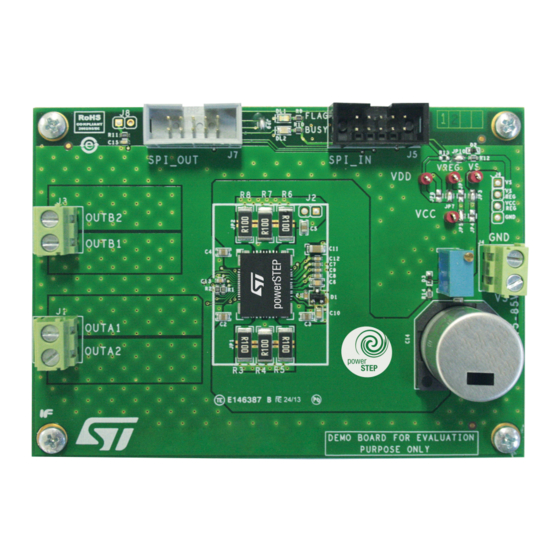
Figure 1.
EVLPOWERSTEP01 evaluation board
UM1829 - Rev 2 - March 2022
www.st.com
For further information contact your local STMicroelectronics sales office.
Advertisement
Table of Contents

Related Manuals for ST PowerSTEP01 EVLPOWERSTEP01


Summary of Contents for ST PowerSTEP01 EVLPOWERSTEP01
-
Page 1: Figure 1. Evlpowerstep01 Evaluation Board
With daisy chain configuration support, the board is suitable for evaluation of multimotor applications. Figure 1. EVLPOWERSTEP01 evaluation board UM1829 - Rev 2 - March 2022 www.st.com For further information contact your local STMicroelectronics sales office. -
Page 2: Board Description
UM1829 Board description Board description Table 1. EVLPOWERSTEP01 electrical specifications Parameter Value Supply voltage (VS) 10.5 V to 85 V Maximum output current (each phase) 10 Arms Gate drivers supply voltage (VCC) 7.5 V to 15 V Logic supply voltage 3.3 V Logic interface supply voltage 3.3 V or 5 V... -
Page 3: Table 3. Master Spi Connector Pinout (J5)
UM1829 Board description Name Type Function Jumper VCC to VCCREG jumper Jumper VCCREG to VREG jumper Jumper VREG to VDD jumper Jumper VDD to 3.3 V from SPI connector jumper Jumper Daisy chain termination jumper JP10 Jumper STBY to VS pull-up jumper Table 3. -
Page 4: Evlpowerstep01 Schematics
EVLPOWERSTEP01 schematics Figure 3. EVLPOWERSTEP01 schematic 1 of 2 Application reference 470 nF/25 V 220 nF/100 V 220 nF/100 V 220 nF/100 V 220 nF/100 V BAR43SFILM 47 nF/100 V VS_REG 100 nF/100 V VSREG 470 nF/25 V VCC_REG 100 nF/25 V 3.3 nF/6.3 V VCCREG VREG... -
Page 5: Figure 4. Evlpowerstep01 Schematic 2 Of 2
Figure 4. EVLPOWERSTEP01 schematic 2 of 2 VS_REG VCC_REG VREG 10.5 V - 85 V OPTION C14A /100 V /100 V VREG STCK STCK SPI_IN BUSY FLAG VS_REG VCC_REG STCK STBY_RESET VS_REG VCC_REG LED - AMBER LED - RED SPI_OUT N.M. -
Page 6: Evlpowerstep01 Bill Of Materials
UM1829 EVLPOWERSTEP01 Bill of materials EVLPOWERSTEP01 Bill of materials Table 5. Bill of materials Manufacturer's Value / generic part ordering code / Index Qty. Reference Package Manufacturer number orderable part number C1, C8 470 nF/25 V CAPC-0603 C2, C3, C4, C5 220 nF/100 V CAPC-0805 47 nF/100 V... - Page 7 Index Qty. Reference Package Manufacturer number orderable part number TP1, TP2, VS, VREG, VDD, TP-RING-RED TPTH-RING- 1 MM VCC, STCK MLPQ85L powerSTEP01 STMicroelectronics POWERSTEP01 - 140 x 110 x 100 - 89 - ST UM1829 - Rev 2 page 7/21...
-
Page 8: Evaluation Environment Setup
A Windows® 7 or Windows XP PC with a free USB port. • The SPINFamily evaluation tool (the last version can be downloaded from www.st.com). In order to start using the evaluation environment the following steps are required: Install the SPINFamily evaluation tool. -
Page 9: Device Configuration
UM1829 Device configuration Device configuration This section offers an overview of the basic configuration steps which are required for make the demonstration board operative. More details about the configuration of the gate driving circuitry and the control algorithms are available in the specific application notes. Important: The device configuration is mandatory;... -
Page 10: Gate Drivers
UM1829 Gate drivers Gate drivers The charge supplied by the device at each commutation is equal to the gate current (I ) multiplied by the gate controlled current time (t ). This value must be greater of the total gate charge (Q ) required to turn on the integrated MOSFETs. -
Page 11: Sensing Resistors
UM1829 Sensing resistors Sensing resistors In the advanced current control mode, the output current range is determined by the sensing resistors as 7.8mV indicated in the following formulas: I peak, min = R sense I peak, max = R sense Where 7.8 mV and 1 V are the minimum and the maximum value of the TVAL registers. -
Page 12: How To Change The Supply Configuration Of The Board
UM1829 How to change the supply configuration of the board How to change the supply configuration of the board The configuration of the supply voltages can be changed through the jumpers from J3 to J8 as listed in Table Table 8 Table Table 7. -
Page 13: Daisy Chaining
UM1829 Daisy chaining Daisy chaining More demonstration boards can be connected in the daisy chain mode. To drive two or more boards in daisy chain configuration: Connect the STEVAL-PCC009V2 board 10-pin connector to the SPI_IN connector of the first demonstration board through the 10-pole flat cable. -
Page 14: Evlpowerstep01 Transient Thermal Analysis
UM1829 EVLPOWERSTEP01 transient thermal analysis EVLPOWERSTEP01 transient thermal analysis Test setup: • Supply voltage V = 24 V • Load RL type: R = 3.5 Ω, L = 400 μH for each phase • Load current 3.5 A for each phase (4.2 A peak •... -
Page 15: Figure 6. Powerstep01 Full-Step Phase Currents
UM1829 EVLPOWERSTEP01 transient thermal analysis Figure 6. powerSTEP01 full-step phase currents Measured data: • Ambient and Junction temperature ≅ 1.5 W) • Device power dissipation (P T j − T amb Z tℎ t = P DUT Figure 7. EVLPOWERSTEP01 transient thermal impedance 1000 10000 Time [s]... -
Page 16: Figure 8. Evlpowerstep01 Power Dissipation Curve
UM1829 EVLPOWERSTEP01 transient thermal analysis Assuming a maximum junction temperature of 150°C, the power dissipation curve is shown in the following figure. Figure 8. EVLPOWERSTEP01 power dissipation curve Temperature [°C] Note: All the results are board-specific. UM1829 - Rev 2 page 16/21... -
Page 17: Revision History
UM1829 Revision history Table 10. Document revision history Date Version Changes 07-Oct-2014 Initial release. PowerSTEP01 added to title Moved Figure 3 Figure 4 from Section 1 Section 1.1 24-Mar-2022 Moved Table 5 from Section 1 Section 1.2 Added Section 7 UM1829 - Rev 2 page 17/21... -
Page 18: Table Of Contents
UM1829 Contents Contents Board description ..............2 EVLPOWERSTEP01 schematics . - Page 19 UM1829 List of figures List of figures Figure 1. EVLPOWERSTEP01 evaluation board ........... 1 Figure 2.
- Page 20 UM1829 List of tables List of tables Table 1. EVLPOWERSTEP01 electrical specifications ..........2 Table 2.
- Page 21 ST’s terms and conditions of sale in place at the time of order acknowledgment. Purchasers are solely responsible for the choice, selection, and use of ST products and ST assumes no liability for application assistance or the design of purchasers’...
Need help?
Do you have a question about the PowerSTEP01 EVLPOWERSTEP01 and is the answer not in the manual?
Questions and answers