Table of Contents

Subscribe to Our Youtube Channel
Related Manuals for McQuay RPS


Summary of Contents for McQuay RPS
- Page 1 Installation and Maintenance Manual IM-738 Group: Applied Systems Part Number: IM-738 Date: April 2002 RoofPak Singlezone Roof Mounted ® Heating and Cooling Units with Scroll Compressors RPS/RDT/RFS/RCS 015-075C © 2002 McQuay International IM-738 Page 1...
-
Page 2: Table Of Contents
Typical Condensing Unit Control for RPS Condenser Fan Arrangement ............6 with MicroTech II Control ............58 Refrigerant Circuit Schematic ............6 Typical Condensing Unit Control w Control Schematic for RPS Refrigeration Piping ..............7 (Controls by Others, 6 Compressor Unit ........59 Control Locations ...............10 Typical Supply / Return Fan Control Circuit Wiring Control Panel Locations .............12... -
Page 3: Introduction
C = Condensing Section Only D = Draw through Cooling Blow through cooling = S Draw through cooling = T Design Vintage Nominal Capacity (Tons) RPS, RFS, RCS, RDT: 015, 018, 020, 025, 030, 036, 040, 045, 050, 060, 070, 075 IM-738 Page 3... -
Page 4: Unit Description
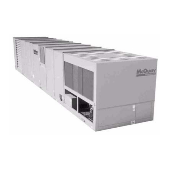
Unit Description Typical Component Locations Figure 1 shows a typical RPS unit with the locations of the are for reference only. See the certified submittals for actual major components. Figure 2 on page 5 shows a typical RDT specific dimensions. - Page 5 Figure 2. Component Locations - RDT Units IM-738 Page 5...
-
Page 6: Condenser Fan Arrangement
Condenser Fan Arrangement Table 2 shows the condenser fan numbering conventions and locations for each unit size. Table 2: Condenser Fan Arrangement REFRIGERANT REFRIGERANT UNIT SIZE ARRANGEMENT UNIT SIZE ARRANGEMENT CIRCUIT CIRCUIT C O N D A H U 015C 045C 018C 1 or 2... -
Page 7: Refrigeration Piping
Refrigeration Piping This section presents the unit refrigeration piping diagrams for conventions are also shown. Refer to Figure 4, Figure 5 on the various available configurations. Component numbering page 8 and Figure 6 on page 9. Figure 4. Condenser Piping 4 Compressors/2 Circuits (045C - 060C) — 3 Compressors/2 Circuits (070 - 075C) Legend 1 - Discharge Shut-off Valve - Circuit #1 2 - Liquid Shut-off Valve - Circuit #1... - Page 8 Figure 5. Air Handler Piping (Flat DX) Legend 1 - Filter-Drier 2 - Liquid Line Solenoid Valve 3 - Sightglass 4 - Hot Gas Bypass Solenoid Valve (Optional) 5 - Hot Gas Bypass Valve (Optional) 6 - Thermostatic Expansion Valve 7 - Distributor Page 8 IM-738...
- Page 9 Figure 6. Air Handler Piping (Staggered DX) Legend 1 - Filter-Drier 2 - Liquid Line Solenoid Valve 3 - Sightglass 4 - Hot Gas Bypass Solenoid Valve (Optional) 5 - Hot Gas Bypass Valve (Optional) 6 - Thermostatic Expansion Valve 7 - Distributor IM-738 Page 9...
-
Page 10: Control Locations
Control Locations Figure 7 (RPS Units) and Figure 8 on page 11 (RDT Units) panels. Additional information is included in Table 3 on show the locations of the various control components mounted page 18 and the wiring diagram legend which is included in throughout the units. - Page 11 Figure 8. Control Locations - RDT Units IM-738 Page 11...
-
Page 12: Control Panel Locations
Control Panel Locations The unit control panels and their locations are shown in the these figures depending on the particular unit options. See following figures. These figures show a typical unit configura- “Wiring Diagrams” on page 54 for the Legend and compo- tion. - Page 13 Figure 10. Main Control Panel - 015 - 040" E H B # 1 C C B # 1 M S T P - E R B # 1 B A C N E T E T H E R N E T L O N W O R K S C O M M C O M M...
- Page 14 Figure 11. Main Control Panel - 045 - 075 E H B # 1 C C B # 1 M S T P - E R B # 1 E T H E R N E T B A C N E T C O M M L O N W O R K S C A R D...
- Page 15 Figure 12. Condenser Control Panel with MicroTech II (015C thru 030C ) Figure 13. Condenser Control Panel with MicroTech II (036C thru 060C) IM-738 Page 15...
- Page 16 Figure 14. Condenser Control Panel with MicroTech II (045 thru 075) Figure 15. Condenser Control Panel with No Controls - RPS (036 thu 075) Figure 16. Condenser Control Panel with No Controls - RPS (015 thu 030 Page 16 IM-738...
- Page 17 Figure 17. Electric Heat Control Panel - sizes 15 - 40C Figure 18. Electric Heat Control Panel - Sizes 45 - 75C IM-738 Page 17...
-
Page 18: Controls, Settings, And Functions
Controls, Settings, and Functions Table 3 and Table 4 on page 19 present a listing of all the unit tion, its location, any device setting, any setting ranges, differ- control devices. Included in the table are the device symbol, a entials, and the device part number. - Page 19 Table 4: Controls, settings and functions (continued) SYMBOL DESCRIPTION FUNCTION RESET LOCATION SETTING RANGE DIFFERENTIAL PART NO. Return air enthalpy Used to compare return air Economizer 049262202 sensor enthalpy to outside air enthalpy section (used with OAE). Return air Senses return air temperature. Return air 3K ohms at 060004705...
-
Page 20: Mechanical Installation
Mechanical Installation Receiving Inspection The installation of this equipment shall be in accordance with the regulations of authorities having jurisdiction and all appli- When the equipment is received, all items should be carefully cable codes. It is the responsibility of the installer to determine checked against the bill of lading to be sure all crates and car- and follow the applicable codes. -
Page 21: Ventilation Clearance
Ventilation Clearance Do not locate outside air intakes near exhaust vents or other sources of contaminated air. Following are minimum ventilation clearance recommenda- tions. The system designer must consider each application If the unit is installed where windy conditions are common, and provide adequate ventilation. -
Page 22: Roof Curb Assembly And Installation
Assembly of a typical RPS/RDT roof curb is shown in RCS Assembly instructions (Figure 21 ) Figure 22 on page 23. Parts A through K are common to all 1. - Page 23 Figure 22. RPS/RFS Roof Curb Assembly D e t a i l B N o t e : “Z” "W" UNIT “X” “Y” “XX” “YY” RPS UNIT SIZE SIZE 015C—030C 45.9 1165 20.0 NONE 24.0 610 82.0 2083 036C & 040C 94.0...
-
Page 24: Post And Rail Mounting
Post and Rail Mounting Rigging and Handling When mounting by post and rail, the structural support should Lifting brackets with 2" (51 mm) diameter holes are provided be run the full length of the unit. The structural member should on the sides of the unit. be located at the base of the unit as shown in Figure 23 assur- Use spreader bars, 96"... - Page 25 Lifting Points Figure 25. Unit Type RPS/RDT Lifting Points To determine the required lifting cable lengths and whether four-or six-point lifting is required, use Table 5 & Table 6 and Figure 25 & Figure 26. Referring to Figure 25 & Figure 26, note that dimension A is the distance between the outer lifting points.
-
Page 26: Reassembly Of Split Units
3. The RPS/RDT unit factory split at the fan ships as two pieces, split at the supply fan bulkhead, to be recoupled together on the roof. Like the RPS/RDT unit factory split... -
Page 27: Rps Factory Split At Condenser
In this case, the bolts and lifting brackets shown in Step 1 should be left in place. Field reassembly of an RPS/RDT unit that has shipped split at the condenser takes place in three phases: Phase 2. Reconnecting Refrigerant Piping All refrigerant piping required to reconnect the two sections is Phase 1. - Page 28 Figure 30. RFS/RCS 015-030 Refrigerant Piping Connections Note: RFS units with front discharge do NOT include refrigerant piping to the DX coil. Field piping is required. Figure 31. RFS/RCS 036 & 040 Refrigerant Piping Connections Note: RFS units with front discharge do NOT include refrigerant piping to the DX coil. Field piping is required. Table 7: Connection Sizes Connection Locations...
- Page 29 Figure 32. RPS (Split) / RFS/RFR 045-135 RCS 045-075 Refrigerant Piping Connections Note: RFS units with front discharge do NOT include refrigerant piping to the DX coil. Field piping is required. Table 8: Connection Sizes Connection Locations Component Circuit RPS (Split) RFS/RFR 045 - 075C...
- Page 30 Step 2. Install condenser supports as shown in Figure 33. Figure 33. RPS/RDT Split at Condenser Reassembly - Step 2 Step 3. Set the condensing unit in place as shown in Figure 34. CAUTION Do not damage piping components while setting condensing unit in place.
- Page 31 Step 4. After condensing unit is set in place, install parts as shown in Figure 35. Figure 35. RPS/RDT Split at Condenser Reassembly - Step 4 Step 5. Make refrigerant piping and electrical connections. See Figure 30 and Figure 31 on page 28 and Figure 32 on page 29.
- Page 32 Reconnecting Power and Control Wiring Figure 36. Connecting Power and Control Wiring (015-040) Units that ship split at the condenser section have complete wire harnesses for power and control wiring just as if they were a package. However, if the installed harness terminates in both the condensing section and air handler section and crosses the split, then only the condensing end is factory con- nected.
-
Page 33: Rps/Rdt Factory Split At Fan
Phase 2. Reconnecting Power and Control Wiring The DX coil/condenser section contains power and control Field reassembly of an RPS/RDT unit that has shipped split at harnesses which have their excess length in the blank or heat the fan takes place in two phases: section that is normally immediately downstream of the fan. - Page 34 Step 2. Set fan end of unit and discharge end of unit in place. Step 3. Caulk and install parts as shown in Figure 40. Figure 40. Split at Fan Reassembly (RPS 045-075 only) - Step 3 Step 4. Make electrical connections and reinstall Inner Raceway Cover as shown in Figure 41.
-
Page 35: Piping Recommendations
This should be noted and Enough refrigerant vapor is then added to the system to reported to the McQuay sales representative and freight car- bring the pressure up to 0 pounds (0 microns). rier if the loss is due to shipping damage. - Page 36 3-1/2 x No. of DX rows *DX coil configuration (S = Standard, L = Large) is identified by the 8th digit of the RPS/RDT or RFS model number, found on the unit nameplate. For example, DX = L for unit model number RFSO6OCLY.
-
Page 37: Refrigeration Service Valves
The unit is shipped with all refrigeration service valves closed. RDT, RPS and RCS units have the following: RFS units do not ship with service valves installed. Before attempting to start the compressors, all refrigeration service Discharge Valve - One per refrigerant circuit, located between valves should be fully opened and backseated. -
Page 38: Subcooling
The unit and drain pan must be level side to side and a P-trap must be installed for proper drainage. RPS units may have positive or negative pressure sections. It is recommended that traps be used in both cases with care given to negative pressure sections. -
Page 39: Steam Coil Piping
The on-off control only. freezing of coils is not the responsibility of McQuay 3. Locate traps at least 12" (305 mm) below the coil return International. Refer to “Winterizing Water Coils” on page 96. -
Page 40: Damper Assemblies
Figure 44. Valve Assembly Figure 46. Damper Adjustment Figure 45. Steam Valve Package Damper Assemblies The optional damper assemblies described in this section are provided with manually adjustable linkages, or may be shipped with factory installed actuators and linkages. Economizer Dampers Outside air intake is provided on both sides of the unit, and the return air path is at the center of the damper set. -
Page 41: Cabinet Weatherproofing
McQuay roof curb is not used. Do not support the total weight of the ductwork from the unit or these duct flanges. -
Page 42: Installing Duct Static Pressure Sensor Taps
Where return air ducts are not required, it is recommended that NOTICE a sound absorbing T or L section be connected to the unit Installer must provide access in the ductwork for return to reduce noise transmission to the occupied space. plenum mounted controls. - Page 43 Figure 51. Pressure Sensing Tubing Installation 5. Use a static pressure tip (Dwyer A302 or equivalent) or the bare end of the plastic tubing for the duct tap. (If the duct is lined inside, use a static pressure tip device.) 6.
-
Page 44: Electrical Installation
Wires should be sized for a maximum of 3% voltage drop. Figure 52. RPS/RDT and RFS Power Wiring Connections Supply voltage must not vary by more than 10% of nameplate. Phase voltage imbalance must not exceed 2%. (Calculate the average voltage of the three legs. - Page 45 This circuit is powered by a field connected 15A, 115V response to ambient air temperature. This feature maintains power supply. Leads are brought into the RFS and RPS units head pressure and allows the unit to run at low ambient air through a 7/8"...
- Page 46 Figure 54. RCS 015C-030C Power Wiring Connections Table 16: Multiple Point Power Connection Options Number of Disconnect Location (See Electrical Load Designation Figure 21) Circuits Supply & return tan Main control panel motors Balance of unit Main control panel Electric heat Electric heat control panel Balance of unit...
-
Page 47: Field Control Wiring
Bulletin No. IM 696, "MicroTech II Applied Rooftop Unit Class I wiring system. Controller." Refer to the unit wiring diagrams for additional Figure 57. RDT, RFS, RPS Field Control Wiring Connections installation information. Wiring must comply with applicable codes and ordinances. -
Page 48: Preparing Unit For Operation
Preparing Unit for Operation Figure 60. Supply Fan Assembly - All Units WARNING Moving machinery hazard. May cause severe injury or death. Disconnect power and lock off before servicing equipment. More than one disconnect may be required to de-energize unit. Relief Damper Tie-Down Economizer sections with a 30"... -
Page 49: Adjustment Of Scroll Dampers
Adjustment of Scroll Dampers Figure 63. Thrust restraint adjustment Two sets of scroll dampers are provided in the housing of the twin 15" x 6" supply fan to allow control of air volume to each fan wheel. At the factory, these dampers are fully closed unrestricting airflow. -
Page 50: Adjustment Of Seismic Restraints
Adjustment of Seismic Restraints Figure 64. Cross Section of Seismic Restraint Spring mounted supply air and return air fans may be ordered with factory installed seismic restraints. The system consists of four snubbers, one located next to each spring isolator. These snubbers will allow free movement of the fan assem- blies during normal operation because normal operation will not cause fan movements that exceed .25"... -
Page 51: Sequences Of Operation
Sequences of Operation Fan Operation The following sequences of operation are for a typical "C" vin- tage applied rooftop unit that is equipped with MicroTech II, When the supply and return fans are commanded to start by an economizer, 4 compressor/4stage cooling, 3 to 1 turn down the Microprocessor Control Board (MCB), the unit enters the burner, variable frequency drives (VFD), a return air fan and Startup Initial operating state. -
Page 52: Mechanical Cooling Operation
CCB1-BO4 output will energize and open liquid line solenoid valve SV1 (line 841), allowing refrigerant to flow Refer to “Typical Condensing Unit Control for RPS with into the evaporator coil. As the refrigerant evaporates, the MicroTech II Control (4 Compressor Unit Shown. RCS has suction pressure increases until low pressure switch LP1 minor variations)”... -
Page 53: Heating
BO4 de-energizes to close liquid line solenoid valve SV1 will ignite and be detected by FSG through flame rod FD (line 841). As a result, compressor #1 pumps down refrigera- (line 622). Upon detection of pilot flame after the 10 second tion circuit #1 until the suction pressure drops low enough to trial for ignition period, the FSG will de-energize terminal 10 open low pressure control LP1 (line 820). -
Page 54: Wiring Diagrams
PS3 ....Pumpdown Switch, Unit ..........Main Control Box C21 .....Capacitor, SpeedTrol (Circuit #2) .........Cond. Bulkhead PVM1 ....Phase Voltage Monitor, RPS Unit .........Main Control Box COMPR.#1, 2 ..Compressors 1 & 2 ............Condenser Sect. PVM2 ....Phase Voltage Monitor, RCS Unit .........Cond./Fuse Ctrl Box CS1, 2....Control Switches, Refrigerant Circuits......Cond. -
Page 55: Typical Power Circuit Wiring
Typical Power Circuit Wiring (6 Compressor Arrangement with VFD Shown) IM-738 Page 55... -
Page 56: Typical Main Circuit Wiring
Typical Main Circuit Wiring (with Inlet Vane and Controls by Others) Page 56 IM-738... -
Page 57: Typical Main Circuit Wiring (Vfd & Controls By Others)
Typical Main Circuit Wiring (with VFD and Controls by Others) Microtech II Schematics are in OM-696 IM-738 Page 57... -
Page 58: Typical Condensing Unit Control For Rps With Microtech Ii Control
Typical Condensing Unit Control for RPS with MicroTech II Control (4 Compressor Unit Shown. RCS has minor variations) Page 58 IM-738... -
Page 59: Typical Condensing Unit Control W Control Schematic For Rps
Typical Condensing Unit Control with Control Schematic for RPS (Controls by Others, 6 Compressor Unit Shown, RCS Has Minor Variations) IM-738 Page 59... -
Page 60: Typical Supply / Return Fan Control Circuit Wiring (No Controls)
Typical Supply / Return Fan Control Circuit Wiring (No Controls) Page 60 IM-738... -
Page 61: Typical Gas Furnace Control Circuit (Modulating Burner, Mixed Air Intake)
Typical Gas Furnace Control Circuit (Modulating Burner, Mixed Air Intake) IM-738 Page 61... -
Page 62: Unit Options
(LPI and LP2). The low ambient start sequence of operation is described below. Refer to “Typi- cal Condensing Unit Control with Control Schematic for RPS (Controls by Others, 6 Compressor Unit Shown, RCS Has Phase Voltage Monitor Minor Variations)”... -
Page 63: Hot Gas Bypass
Hot Gas Bypass charge air temperature setting while observing the suction pressure. When the bypass valve starts to open, the refrigerant Hot gas bypass is a system for maintaining evaporator pressure line on the evaporator side of the valve will begin to feel warm at or above a minimum value. -
Page 64: Speedtrol (Na Unit Sizes 015C - 030C)
The SpeedTrol controller's throttling range is 170 to 230 psig (1172-1586 kPa) fixed. McQuay's SpeedTrol system of head pressure control oper- The SpeedTrol fan motor is a single phase, 208/240 volt, ates in conjunction with FanTrol by modulating the motor... -
Page 65: External Time Clock
External Time Clock The unit will remain shut down until the "Freeze Stat Fail" alarm is manually cleared. Refer to the operation manual An external time clock can be used as an alternative to (or in supplied with the unit for information clearing alarms (page addition to) the MicroTech II controller's internal scheduling 55, OM138 or page 58, Om137). -
Page 66: Variable Inlet Vanes
Variable Inlet Vanes Variable inlet vanes are installed on the supply and return fans NOTICE of VAV units. They are also installed on the return fans of con- stant volume units that have direct building static pressure con- Inlet vanes must not be adjusted to close tight during fan operation. - Page 67 Figure 69. Supply Fan or Return Vane Assembly (RPS 15-40) Figure 70. Return Fan Vane Assembly IM-738 Page 67...
- Page 68 Figure 71. Supply Fan Vane Assembly (RPS 45-075) Note: Dimension "Z" is referenced in Table 19 on page 66 Figure 72. Return Fan Vane Assembly (40" Wheels) Page 68 IM-738...
- Page 69 Figure 73. Return Fan Vane Assembly (RPS - 44" Wheels) Figure 74. Supply Fan Assembly (40" Wheels - RDT 45 - 075) IM-738 Page 69...
- Page 70 Figure 75. Supply Fan Vane Assembly (44" Wheels - RDT 45 - 135) Page 70 IM-738...
-
Page 71: Variable Frequency Drive Operation
Variable Frequency Drive Operation DesignFlow Airflow Measurement Station Startup: Refer to the vendor instructions supplied with the unit. Note: Before starting the station startup procedure, locate Convenience Receptacle/Section Lights the leveling components kit that can be found in the A convenience receptacle is provided in the main control box main unit control box. - Page 72 Figure 77. Tape Fulcrum Alignment Plate to Vane Figure 78. Place Leveling Weight on Fulcrum 5. Tape the fulcrum Alignment Plate to the vane (See Figure 77). Locate the Alignment Plate so the bottom edge of its notches are flush with the bottom edge of the vane, one side of one notch is even with the bend near the outer edge of the vane, and the plate is flat against the outer surface of the vane.
-
Page 73: Propeller Exhaust Fan Option
Figure 79. Leveling Adjustment 11. After leveling, remove fulcrum and replace the access opening covers. Propeller Exhaust Fan Option Economizer units may include propeller exhaust or centrifu- gal return fan options. This section covers maintenance and operating instructions for the propeller exhaust option. Cen- trifugal return fan construction, maintenance and operation is similar to that for supply fans and covered in other sections of this manual. - Page 74 Figure 82. Belt Adjustment groove variable pitch pulleys must be adjusted an equal num- ber of turns open. Any increase in fan speed represents a sub- stantial increase in horsepower required from the motor. Always check motor load amperage and compare to name plate rating when changing fan speed.
- Page 75 With the unit running, add grease very slowly with a manual Motors equipped with oil holes should be oiled in accordance grease gun until a slight bead of grease forms at the seal. Be with the manufacturer's instructions printed on the motor. careful not to unseat the seal by over lubricating or using Use a high grade SAE 20 machine oil and use caution not to excessive pressure.
-
Page 76: Propeller Exhaust Fan Control
Propeller Exhaust Fan Control Exhaust Fan Speed Control The exhaust fan variable frequency drive can be controlled Exhaust Fan On/Off Control by two different methods that maintain building static pres- The Exhaust fans are turned on and off based on building static sure. -
Page 77: Check, Test, And Start Procedures
28B ("Timers=") from "Normal" to signed, and returned to McQuay International. "Fast." This will reduce the delays associated with nor- A representative of the owner or the operator of the equipment... -
Page 78: Economizer Start-Up
3. If the fans are equipped with optional spring isolators, II controller by turning the switch to "A" or "D". Check check the fan spring mount adjustment. When the fans are menu 9. If the changeover occurred, go to step 5. running they should be level. - Page 79 Figure 85. Condenser Fan Blade Positioning it is getting three-phase power. The compressor should operate continuously while there is a call for cooling. If the compressor stops because the oil pressure switch trips, see "Oil Pressure" below. If the compressor cycles on its low pressure switch, do the fol- lowing: a.
-
Page 80: Heating System Start-Up
Expansion Valve Superheat Adjustment Steam Heat It is very important that the expansion valve superheat setting The steam valve actuator should open the valve. The steam be adjusted to be between 10° F (-12° C) and 13° F (-11° C). valve is open when the valve stem is up. -
Page 81: Sheave Alignment
Sheave Alignment Drive Belt Adjustment Mounting: General Rules of Tensioning 1. Verify both driving and driven sheaves are in alignment 1. The ideal tension is the lowest tension at which the belt and the shafts are parallel. The center line of the driving will not slip under peak load conditions. -
Page 82: Mounting And Adjusting Motor Sheaves
Table 21: Belt Deflection Force (not applicable for Exhaust Fans - see “Belts” on page 74 SHEAVE DIAMETER (INCHES) DEFELCTION FORCE (LBS.) BELT DEFLECTION FORCE CROSS SECTION SMALLEST SHEAVE RPM RANGE CROSS SECTION A, B, 5V CROSS SECTION AX, BX, 5VX DIAMETER RANGE USED BELT NEW BELT... - Page 83 6. Be sure that all keys are in place and that all setscrews are 6. Replace key "F". tight before starting the drive. Check the setscrews and 7. Tighten setscrews "D" and capscrews "E". belt tension after 24 hours of service. 8.
- Page 84 Figure 89. LVP variable pitch sleeves S e c t i o n A - A S e c t i o n A - A Figure 90. MVP variable pitch sheaves (type A-B) Figure 91. MVP variable pitch sheaves (type A-B) Page 84 IM-738...
-
Page 85: Rooftop Equipment Warranty Registration Form
This form must be filled out and returned to McQuay, Warranty Department, within 10 days in order to comply with the terms of McQuay Warranty. Check, Test and Start Procedure for RoofPak roof mounted air conditioners with or without heat recovery; roof mounted air handlers and SuperPak roof mounted supermarket units. - Page 86 Warranty Registration Form (continued) Compressor lockout timers function (5 minutes) ....................Yes Does unit start-up and perform per sequence of operation?................Yes PERFORMANCE DATA Compressor voltage across each phase: _________ 1-2 V__________ 2-3 V __________1-3 V Compressor amperage of fully loaded compressor: Phase Compressor #1........1 ______________ 2 ______________ 3_______________ Compressor #2........1 ______________ 2 ______________ 3 _ _______________...
- Page 87 Signature: _______________________________________________________ Date of Start-up: ____________________________ RETURN COMPLETED FORM TO: McQuay International Warranty Department, 13600 Industrial Park Boulevard, Minneapolis, MN 55441 Comments: Please list any additional comments which could affect the operation of this unit; i.e., shipping damage, failed components, adverse installation applications, etc., on a separate sheet and attach to this form.
- Page 88 Poor How would you rate the overall quality of the product? Excellent Good Fair Poor How does the quality of McQuay products rank in relation to competitive products? Excellent Good Fair Poor Comments: Please list any additional comments which could affect the operation of this unit; i.e., shipping damage, failed components, adverse installation applications, etc., on a separate sheet and attach to this form.
-
Page 89: Final Control Settings
Final Control Settings When all start-up procedures have been completed, set the 14.Set the economizer control parameters as required controls and program the MicroTech II controller for normal (keypad menu 21). operation. Use the following list as a guide; some items may 15.Set the dirty filter set points as required (keypad menu not apply to your unit. - Page 90 Figure 92. Keypad Accessible Menu Structure Page 90 IM-738...
- Page 91 Figure 93. Keypad Accessible Menu Structure (continued) IM-738 Page 91...
- Page 92 Figure 94. Keypad Accessible Menu Structure (continued) Page 92 IM-738...
-
Page 93: Maintenance
17.Lubricate the door latch mechanisms. Unit Storage Location WARNING The McQuay Rooftop Packaged System Unit is an outdoor Moving machinery and electrical power hazards. unit. However, the schedule may dictate storage either on the May cause severe personal injury or death. -
Page 94: Gas Furnace
Use one of the greases shown in Control Compartment Table 22. 1. McQuay International recommends that the electronic con- While the bearing is at normal operating temperatures, rotate trol equipment in the unit be stored in a 5% to 95% RH the fan by hand and add only enough grease to purge the (non-condensing) environment. -
Page 95: Setscrews
Figure 95. Return Fan Assembly b. Bad V-belts; lumpy, or mismatched; belt tension too tight or too loose. 4. Bad bearings, loose bearing hold-down bolts. 5. Motor imbalance. 6. Fan section not supported evenly on foundation. Periodic Service and Maintenance 1. -
Page 96: Refrigerant Charge
Replace switch after reclaiming refrigerant. Replacing Failed Refrigerant Sensors or Switches The McQuay Rooftop Unit includes the following refrigerant Table 26: Airfoil Wheel-to-Funnel Tolerances sensors or switches. Wheel-to-Funnel Relationship (In Inches) 1. Low refrigerant sensing, operating switch Wheel Diameter Inches) “A”... -
Page 97: Replacement Parts List
Replacement Parts List Table 29: Microtech II Components Parts List Component McQuay Part Description Designation Number Main Control Board 060006101 CCB1 Auxiliary Cooling Control Board (DX Circuit #1 or Generic Condenser) 106102701 CCB2 Auxiliary Cooling Control Board (DX Circuit #2) -
Page 98: Service And Warranty Procedure
If able on the RPS25-30 (tandems and the RPS circuit #1 replacement parts are required, include the date of unit instal- tandem). -
Page 99: Limited Product Warranty (North America)
Company, including have been opened, disassembled, repaired, or altered by products sold under the brand names McQuay Air Conditioning, anyone other than Company or its authorized service rep- AAF Air Conditioning, AAF HermanNelson and McQuay Ser- resentative;... - Page 100 This document contains the most current product information as of this printing. For the most up-to-date product information, please go to www.mcquay.com. © 2002 McQuay International • www.mcquay.com • 800-432-1342 Page 100 IM-738...
Need help?
Do you have a question about the RPS and is the answer not in the manual?
Questions and answers
I have a RPS018BA and engineer wants to know the weight of the unit
The weight of the McQuay RPS018BA unit is 2,388 lbs.
This answer is automatically generated