Table of Contents
Advertisement
Quick Links
Advertisement
Table of Contents

Related Manuals for Hitachi RIO3-Y Series


Summary of Contents for Hitachi RIO3-Y Series
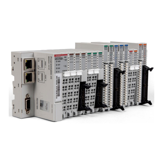
- Page 1 HX-RIO3 Series Digital Output Module RIO3-Y… User Manual Version 1.011...
- Page 2 HX-RIO3 Series REVISION HISTORY PAGE REMARKS DATE EDITOR 1.01 New Document Nov 2020 (OPR), (PF) 1.01 Remove product list table and add a reference Aug 2021 Faber 1.011 RIO3-YTP8L. RIO3-YTP16L added Aug 2022 Faber...
-
Page 3: Table Of Contents
HX-RIO3 Series Important Notes ............................5 Safety Instructions ..........................6 1.1.1 Symbols ............................. 6 1.1.2 Safety Notes ..........................6 1.1.3 Certification ..........................6 Digital Output Module List .......................... 7 Specification ............................... 8 RIO3-YTP8 ............................8 3.1.1 Wiring Diagram .......................... 8 3.1.2 LED Indicator .......................... - Page 4 HX-RIO3 Series 3.6.2 LED Indicator ........................... 33 3.6.3 Channel Status LED ........................ 33 3.6.4 Environment Specification ....................... 34 3.6.5 Specification..........................35 3.6.6 Mapping Data into the Image Table..................36 3.6.7 Parameter Data........................36 RIO3-YS8............................37 3.7.1 Wiring Diagram ........................37 3.7.2 LED Indicator ...........................
-
Page 5: Important Notes
In no event will HITACHI be responsible or liable for indirect or consequential damages resulting from the use or application of this equipment. -
Page 6: Safety Instructions
HX-RIO3 Series 1.1 Safety Instructions 1.1.1 Symbols Identifies information about practices or circumstances that can cause an explosion in a hazardous environment, which may lead to personal injury or death property damage, or economic loss. Identifies information that is critical for successful application and understanding of the product Identifies information about practices or circumstances that can lead to personal injury, property damage, or economic loss. -
Page 7: Digital Output Module List
HX-RIO3 Series 2 Digital Output Module List RIO3-Number Description ID (hex) RIO3-YTP8 Digital Output, 8 Points, Source 24VDC, 0.5A, 10 RTB 2328 RIO3-YTP16C Digital Output,16 Points, Source 24VDC, 0.3A, 20P Connector 222F RIO3-YTP16T Digital Output 16 Points, Source, 18RTB 226F RIO3-YTP32C Digital Output, 32 Points, Source 24VDC, 0.3A, 40P Connector 22CA... -
Page 8: Specification
HX-RIO3 Series 3 Specification 3.1 RIO3-YTP8 3.1.1 Wiring Diagram Pin No. Signal Description Signal Description Pin No. Output Channel 0 Output Channel 1 Output Channel 2 Output Channel 3 Output Channel 4 Output Channel 5 Output Channel 6 Output Channel 7 Common (Field Power 0V) Common (Field Power 0V) -
Page 9: Led Indicator
HX-RIO3 Series 3.1.2 LED Indicator LED No. LED Function / Description LED Color Output Channel 0 Green Output Channel 1 Green Output Channel 2 Green Output Channel 3 Green Output Channel 4 Green Output Channel 5 Green Output Channel 6 Green Output Channel 7 Green... -
Page 10: Specification
HX-RIO3 Series 3.1.5 Specification Items Specification Output Specification Output per module 8 Points Source type Indicators (Logic side) 8 Green Output state 24Vdc Nominal Output Voltage Range Min. 15Vdc to Max. 30Vdc 0.3Vdc @ 25℃ ON-state voltage drop 0.5Vdc @ 70℃ ON-State Min. -
Page 11: Mapping Data Into The Image Table
HX-RIO3 Series 3.1.6 Mapping Data into the Image Table Output Image Value Bit No Bit7 Bit6 Bit5 Bit4 Bit3 Bit2 Bit1 Bit0 Byte0 Output Module Data 3.1.7 Parameter Data Valid Parameter Length: 2 Bytes Parameter Data Bit No Bit7 Bit6 Bit5 Bit4 Bit3... -
Page 12: Rio3-Ytp16C
HX-RIO3 Series 3.2 RIO3-YTP16C 3.2.1 Wiring Diagram Pin No. Signal Description Signal Description Pin No. Output Channel 0 Output Channel 1 Output Channel 2 Output Channel 3 Output Channel 4 Output Channel 5 Output Channel 6 Output Channel 7 Output Channel 8 Output Channel 9 Output Channel 10 Output Channel 11... -
Page 13: Led Indicator
HX-RIO3 Series 3.2.2 LED Indicator LED No. LED Function / Description LED Color Output Channel 0 Green Output Channel 1 Green Output Channel 2 Green Output Channel 3 Green Output Channel 4 Green Output Channel 5 Green Output Channel 6 Green Output Channel 7 Green... -
Page 14: Environment Specification
HX-RIO3 Series 3.2.4 Environment Specification Environmental Specification Operation Temperature -40℃ ~ 70℃ UL Temperature -20℃ ~ 60℃ Storage Temperature -40℃ ~ 85℃ Relative Humidity 5% ~ 90% non-condensing Mounting DIN Rail General Specification Shock Operating IEC 60068-2-27 Based on IEC 60068-2-6 Vibration Resistance DNVGL-CG-0039: Vibration Class B, 4g Industrial Emissions... -
Page 15: Specification
HX-RIO3 Series 3.2.5 Specification Items Specification Output Specification Output Per Module 16 Points Source Type Indicators 16 Green Output Status Nominal 24Vdc Output Voltage Range 15Vdc ~ 30Vdc @ 70℃ 0.3Vdc @ 25℃ ON-state Voltage Drop 0.5Vdc @ 70℃ ON-State Min. Current Min. -
Page 16: Mapping Data Into The Image Table
HX-RIO3 Series 3.2.6 Mapping Data into the Image Table Output Image Value Bit No. Bit7 Bit6 Bit5 Bit4 Bit3 Bit2 Bit1 Bit0 Byte0 Byte1 Output Module Data 3.2.7 Parameter Data Valid Parameter length: 4 Bytes Parameter Data Bit No. Bit7 Bit6 Bit5 Bit4... -
Page 17: Rio3-Ytp16T
HX-RIO3 Series 3.3 RIO3-YTP16T 3.3.1 Wiring Diagram Pin No. Signal Description Signal Description Pin No. Output Channel 0 Output Channel 1 Output Channel 2 Output Channel 3 Output Channel 4 Output Channel 5 Output Channel 6 Output Channel 7 Output Channel 8 Output Channel 9 Output Channel 10 Output Channel 11... -
Page 18: Led Indicator
HX-RIO3 Series 3.3.2 LED Indicator LED No. LED Function / Description LED Color Output Channel 0 Green Output Channel 1 Green Output Channel 2 Green Output Channel 3 Green Output Channel 4 Green Output Channel 5 Green Output Channel 6 Green Output Channel 7 Green... -
Page 19: Environment Specification
HX-RIO3 Series 3.3.4 Environment Specification Environmental specification Operation Temperature -40℃ ~ 70℃ UL Temperature -20℃ ~ 60℃ Non-Operating Temperature -40℃ ~ 85℃ Relative Humidity 5% to 95% non-condensing Mounting DIN Rail General specification Shock Operating IEC 60068-2-27 Based on IEC 60068-2-6 Vibration Resistance DNVGL-CG-0039: Vibration Class B, 4g Industrial Emissions... -
Page 20: Specification
HX-RIO3 Series 3.3.5 Specification Items Specification Output Specification Output per module 16 Points Source type Indicators 16 Green Output state 24Vdc Nominal Output Voltage Range Min. 15Vdc ~ Max. 32Vdc 0.3Vdc @ 25℃ ON-State Voltage Drop 0.5Vdc @ 70℃ ON-State Min. Current Min. -
Page 21: Mapping Data Into The Image Table
HX-RIO3 Series 3.3.6 Mapping Data into the Image Table Output Image Value Bit No. Bit7 Bit6 Bit5 Bit4 Bit3 Bit2 Bit1 Bit0 Byte0 Byte1 Output Module Data 3.3.7 Parameter Data Valid Parameter length: 4 Bytes Parameter Data Bit No. Bit7 Bit6 Bit5 Bit4... -
Page 22: Rio3-Ytp32C
HX-RIO3 Series 3.4 RIO3-YTP32C 3.4.1 Wiring Diagram Pin No. Signal Description Signal Description Pin No. Output Channel 0 Output Channel 1 Output Channel 2 Output Channel 3 Output Channel 4 Output Channel 5 Output Channel 6 Output Channel 7 Output Channel 8 Output Channel 9 Output Channel 10 Output Channel 11... -
Page 23: Led Indicator
HX-RIO3 Series Output Channel 30 Output Channel 31 Common (Field Power 0V) Common (Field Power 0V) Common (Field Power 24V) Common (Field Power 24V) 3.4.2 LED Indicator LED No. LED Function / Description LED Color Output Channel 0 Green Output Channel 1 Green Output Channel 2 Green... -
Page 24: Environment Specification
HX-RIO3 Series 3.4.4 Environment Specification Environmental Specification Operation Temperature -40℃ ~ 60℃ UL Temperature -20℃ ~ 60℃ Storage Temperature -40℃ ~ 85℃ Relative Humidity 5% ~ 90% non-condensing Mounting DIN Rail General Specification Shock Operating IEC 60068-2-27 Based on IEC 60068-2-6 Vibration Resistance DNVGL-CG-0039: Vibration Class B, 4g Industrial Emissions... -
Page 25: Specification
HX-RIO3 Series 3.4.5 Specification Items Specification Output Specification Output Per Module 32 Points Source type Indicators 32 Green Output Status Output Voltage Range 24Vdc nominal 15Vdc ~ 30Vdc @ 60℃ ON-state Voltage Drop 0.3Vdc @ 25℃ 0.5Vdc @ 60℃ ON-State Min. Current Min. -
Page 26: Mapping Data Into The Image Table
HX-RIO3 Series 3.4.6 Mapping Data into the Image Table Output Image Value Bit No. Bit7 Bit6 Bit5 Bit4 Bit3 Bit2 Bit1 Bit0 Byte0 Byte1 Byte2 Byte3 Output Module data 3.4.7 Parameter Data Valid Parameter Length: 8 Bytes Parameter Data Bit No Bit7 Bit6 Bit5... -
Page 27: Rio3-Ys4
HX-RIO3 Series 3.5 RIO3-YS4 3.5.1 Wiring Diagram Pin No. Signal Description Signal Description Pin No. Output Channel 0 COM 0 Output Channel 1 COM 1 Output Channel 2 COM 2 Output Channel 3 COM 3 Common (Field Power 24V) Common (Field Power 0V) -
Page 28: Led Indicator
HX-RIO3 Series 3.5.2 LED Indicator LED No. LED Function / Description LED Color Output Channel 0 Green Output Channel 1 Green Output Channel 2 Green Output Channel 3 Green 3.5.3 Channel Status LED Status To indicate No Signal No Output Signal On Signal Green Normal Operation... -
Page 29: Environment Specification
HX-RIO3 Series 3.5.4 Environment Specification Environmental Specification Operation Temperature -40℃ ~ 70℃ UL Temperature -20℃ ~ 60℃ Storage Temperature -40℃ ~ 85℃ Relative Humidity 5% ~ 90% non-condensing Mounting DIN Rail General Specification Shock Operating IEC 60068-2-27 Based on IEC 60068-2-6 Vibration Resistance DNVGL-CG-0039: Vibration Class B, 4g Industrial Emissions... -
Page 30: Specification
HX-RIO3 Series 3.5.5 Specification Items Specification Output Specification Output Per Module 4 Points Bi-directional Indicators 4 Green Output Status LEDs Relay Type MOS Relay (Solid State Relay) Output Voltage Range Max. 240Vac @ 0.5A resistive (Load Dependent) Max. 240Vdc @ 0.5A resistive Max. -
Page 31: Mapping Data Into The Image Table
HX-RIO3 Series 3.5.6 Mapping Data into the Image Table Output Image Value Bit No. Bit7 Bit6 Bit5 Bit4 Bit3 Bit2 Bit1 Bit0 Byte0 Reserved Output Module data 3.5.7 Parameter Data Valid Parameter Length: 2 Bytes Parameter Data Offset Decimal Bit Description Default Value Fault Action (0~3) -
Page 32: Rio3-Yr4
HX-RIO3 Series 3.6 RIO3-YR4 3.6.1 Wiring Diagram Pin No. Signal Description Signal Description Pin No. Output Channel 0 COM 0 Output Channel 1 COM 1 Output Channel 2 COM 2 Output Channel 3 COM 3 Common (Field Power 24V) Common (Field Power 0V) - Page 33 HX-RIO3 Series 3.6.2 LED Indicator LED No. LED Function / Description LED Color Output Channel 0 Green Output Channel 1 Green Output Channel 2 Green Output Channel 3 Green 3.6.3 Channel Status LED Status To indicate No Signal No Output Signal On Signal Green Normal Operation...
- Page 34 HX-RIO3 Series 3.6.4 Environment Specification Environmental Specification Operation Temperature -40℃ ~ 60℃ UL Temperature -20℃ ~ 60℃ Storage Temperature -40℃ ~ 85℃ Relative Humidity 5% ~ 90% non-condensing Mounting DIN Rail General Specification Shock Operating IEC 60068-2-27 Based on IEC 60068-2-6 Vibration Resistance DNVGL-CG-0039: 2016/6 Vibration Class B, 4g Industrial Emissions...
- Page 35 HX-RIO3 Series 3.6.5 Specification Items Specification Output Specification Output Per Module 4 Points Bi-directional Indicators 4 Green Output Status LEDs Relay Type Form A, Single Pole Single Throw (SPST) 0~32Vdc @ 2A resistive Output Voltage Range 48Vdc @ 0.8A resistive (Load Dependent) 110Vdc @ 0.5A resistive Max.
- Page 36 HX-RIO3 Series 3.6.6 Mapping Data into the Image Table Output Image Value Bit No. Bit7 Bit6 Bit5 Bit4 Bit3 Bit2 Bit1 Bit0 Byte0 Reserved Output Module data 3.6.7 Parameter Data Valid Parameter Length: 2 Bytes Parameter Data Offset Decimal Bit Description Default Value Fault Action (0 ~ 3)
- Page 37 HX-RIO3 Series 3.7 RIO3-YS8 3.7.1 Wiring Diagram Pin No. Signal Description Signal Description Pin No. Output Channel 0_A Output Channel 0_B Output Channel 1_A Output Channel 1_B Output Channel 2_A Output Channel 2_B Output Channel 3_A Output Channel 3_B Output Channel 4_A Output Channel 4_B Output Channel 5_A Output Channel 5_B...
- Page 38 HX-RIO3 Series 3.7.2 LED Indicator LED No. LED Function / Description LED Color Output Channel 0 Green Output Channel 1 Green Output Channel 2 Green Output Channel 3 Green Output Channel 4 Green Output Channel 5 Green Output Channel 6 Green Output Channel 7 Green...
- Page 39 HX-RIO3 Series 3.7.5 Specification Items Specification Output Specification Output Per Module 8 points bi-directional Indicators 8 Green Output State Relay type MOS Relay (solid state relay) Output Voltage Range 240Vac @ 0.5A resistive (Load dependent) 240Vdc @ 0.5A resistive Output delay time Max.
- Page 40 HX-RIO3 Series 3.7.6 Mapping Data into the Image Table Output Image Value Bit No Bit7 Bit6 Bit5 Bit4 Bit3 Bit2 Bit1 Bit0 Byte0 Output Module data 3.7.7 Parameter Data Valid Parameter Length: 2 Bytes Parameter Data Offset Decimal Bit Description Default Value Fault Action (0~7) 00-07...
- Page 41 HX-RIO3 Series 3.8 RIO3-YTP8L 3.8.1 Wiring Diagram Pin No. Signal Description Signal Description Pin No. Output Channel 0 Output Channel 1 Output Channel 2 Output Channel 3 Output Channel 4 Output Channel 5 Output Channel 6 Output Channel 7 Common (Field Power 0V) Common (Field Power 0V)
- Page 42 HX-RIO3 Series 3.8.2 LED Indicator LED No. LED Function / Description LED Color Output Channel 0 Green Output Channel 1 Green Output Channel 2 Green Output Channel 3 Green Output Channel 4 Green Output Channel 5 Green Output Channel 6 Green Output Channel 7 Green...
- Page 43 HX-RIO3 Series 3.8.5 Specification Items Specification Output Specification Output per module 8 points source type Indicators 8 green Output status Output voltage range 24Vdc nominal Min. 15Vdc ~ Max. 30Vdc On-state voltage drop 3.0Vdc @ 2A On-state min. current Min. 1mA Off-state leakage current Max.
- Page 44 HX-RIO3 Series 3.8.6 Wiring information Observe the following instructions for wiring • Observe the maximum Output current of the I/O Module. Parts may be damaged. • Do not connect the input and GND pins without any load. Parts may be damaged. 3.8.7 Mapping Data into the Image Table Output Image Value Bit No...
- Page 45 HX-RIO3 Series 3.9 RIO3-YTP16L 3.9.1 Wiring Diagram Pin No. Signal Description Signal Description Pin No. Output Channel 0 Output Channel 1 Output Channel 2 Output Channel 3 Output Channel 4 Output Channel 5 Output Channel 6 Output Channel 7 Output Channel 8 Output Channel 9 Output Channel 10 Output Channel 11...
- Page 46 HX-RIO3 Series 3.9.2 LED Indicator LED No. LED Function / Description LED Color Output Channel 0 Green Output Channel 1 Green Output Channel 2 Green Output Channel 3 Green Output Channel 4 Green Output Channel 5 Green Output Channel 6 Green Output Channel 7 Green...
- Page 47 HX-RIO3 Series Installation Position Vertical and horizontal installation is possible Product Certifications CE, UL, EAC 3.9.5 Specification Items Specification Output Specification Output per module 16 points source type Indicators 16 green Output status Output voltage range 24Vdc nominal Min. 15Vdc ~ Max. 30Vdc On-state voltage drop 3.00Vdc @ 2A On-state min.
- Page 48 HX-RIO3 Series 3.9.6 Wiring information Observe the following instructions for wiring • Observe the maximum Output current of the I/O Module. Parts may be damaged. • Do not connect the input and GND pins without any load. Parts may be damaged. 3.9.7 Mapping Data into the Image Table Output Image Value Bit No.
- Page 49 HX-RIO3 Series 3.9.8 Parameter Data Valid Parameter Length: 4 Bytes Parameter Data Bit No. Bit7 Bit6 Bit5 Bit4 Bit3 Bit2 Bit1 Bit0 Byte0 Fault Action (ch0 ~ ch7) 0: Fault value, 1: Hold last state Byte1 Fault Action (ch8 ~ ch15) 0: Fault value, 1: Hold last state Byte2 Fault Value (ch0 ~ ch7)
- Page 50 HX-RIO3 Series 4 Dimension 4.1 10-Pts. Spring Type Dimensions in mm...
- Page 51 HX-RIO3 Series 4.2 20-Pin Connector Type Dimensions in mm...
- Page 52 HX-RIO3 Series 4.3 40-Pin Connector Type Dimensions in mm...
- Page 53 HX-RIO3 Series 4.4 18-Pts. Spring Type Dimensions in mm...
- Page 54 HX-RIO3 Series 5 Mounting Caution! Hot surface! The surface of the housing can become hot during operation. If the device was operated at high ambient temperatures, allow it to be cool before touching it. Notice! Perform work on devices only if they are de-energized! Working on energized devices can damage them.
- Page 55 HX-RIO3 Series 5.2 RTB (Removable Terminal Block) Whole terminal block can be combined and removed for the convenience. There is a locking switch on the RTB for the easy combination and easy removal. Easy combination and easy removal for I/O modules on the DIN rail through One Touch Locking Switch.
- Page 56 HX-RIO3 Series 6 G-Bus Pin Description Communication between the Network Adapter and the expansion module as well as system/field power supply of the bus modules is carried out via the internal bus. It is comprised of 6 data pin and 2 field power pin. *Please refer to the table below regarding the pin description from P1 to P8.
- Page 57 HX-RIO3 Series 7 APPENDIX A 7.1 Product List Please refer the separate HX-RIO3 product list document 7.2 Glossary System Power: The power for starting up CPU. Field Power: The power for input and Output line. Terminator Resistor: Resistor for prevention reflected wave. EDS: Electronic Data Sheet.