Emerson Rosemount 700XA Reference Manual
Gas chromatograph
Hide thumbs
Also See for Rosemount 700XA:
- Install (12 pages) ,
- Reference manual (148 pages) ,
- Quick start manual (80 pages)

Related Manuals for Emerson Rosemount 700XA


Summary of Contents for Emerson Rosemount 700XA
- Page 1 Reference Manual 2-3-9000-744, Rev L June 2022 ™ Rosemount 700XA Gas Chromatograph...
- Page 2 Notice EMERSON (“SELLER”) SHALL NOT BE LIABLE FOR TECHNICAL OR EDITORIAL ERRORS IN THIS MANUAL OR OMISSIONS FROM THIS MANUAL. SELLER MAKES NO WARRANTIES, EXPRESSED OR IMPLIED, INCLUDING THE IMPLIED WARRANTIES OF MERCHANTABILITY AND FITNESS FOR A PARTICULAR PURPOSE, WITH RESPECT TO THIS MANUAL AND, IN NO EVENT, SHALL SELLER BE LIABLE FOR ANY SPECIAL OR CONSEQUENTIAL DAMAGES INCLUDING, BUT NOT LIMITED TO, LOSS OF PRODUCTION, LOSS OF PROFITS, ETC.
- Page 3 WARNING Safety compliance Failure to follow the safety instructions may cause injury to personnel. The seller does not accept any responsibility for installations of the device or any attached equipment in which the installation or operation thereof has been performed in a manner that is negligent and/or non-compliant with applicable safety requirements.
- Page 4 NOTICE Replaceable parts Only a few parts inside the device are replaceable. Only trained service personnel should replace parts. All replacement parts must be authorized by Emerson to ensure product certification compliance. NOTICE Equipment damage If the device is heated without carrier flow, damage to the columns may occur.
- Page 5 Glossary Auto zero The thermal conductivity detector (TCD) is auto zeroed at the start of a new analysis. The operator can also configure automatic zeroing of the TCD amplifier to take place at any time during the analysis if the component is not eluting or the baseline is steady.
- Page 6 TxD, TD, or S Transmit data or signal out.
-
Page 7: Table Of Contents
6.2 No power to flame photometric detector (FPD)............... 192 6.3 Can't ignite flame photometric detector (FPD)................ 192 6.4 No peaks showing........................192 6.5 Small peaks..........................193 6.6 No temperature readings......................193 6.7 Noisy baseline..........................193 6.8 Peak clipping........................... 193 6.9 Test points..........................194 6.10 Voltage LEDs..........................195 Rosemount 700XA... - Page 8 D.2 Recommended spare parts for Rosemount 700XA flame ionization detector (FID)/thermal conductivity detector (TCD) analyzers..................272 D.3 Recommended spare parts for Rosemount 700XA flame ionization detector (FID) analyzers.. 273 D.4 Recommended spare parts for Rosemount 700XA micro flame photometric detector (µFPD) analyzers........................
-
Page 9: Chapter 1 Overview
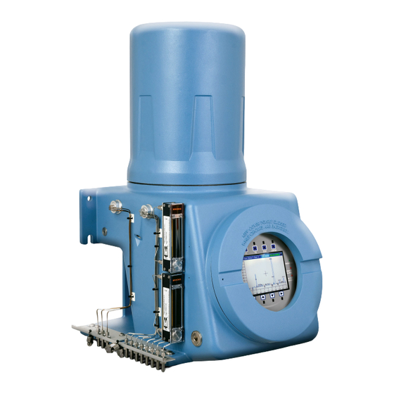
The Rosemount 700XA system consists of two major parts: the analyzer assembly and the electronics assembly. Depending upon the particular GC, there may also be a third, optional assembly called the sample conditioning system (SCS). -
Page 10: Functional Description
Failure to follow this warning may result in injury or death to personnel. Do not use a personal computer (PC) or printer in a hazardous area. Emerson provides serial and Ethernet communication links to connect the analyzer to the PC and to connect to other computers and printers in a safe area. - Page 11 Output from the electronic assembly is normally displayed on a remotely located personal computer (PC) or in a distributed control system (flow computer). Rosemount 700XA...
-
Page 12: Software Description
1.3.1 Embedded gas chromatograph (GC) firmware The GC’s embedded firmware supervises operation of the Rosemount 700XA through its internal microprocessor-based controller. All direct hardware interface is via this control software. It consists of a multitasking program that controls separate tasks in system operation, as well as hardware self-testing, user application downloading, start-up, and communication. - Page 13 Reports and logs that can be produced, depending upon the GC application in use, include, but are not limited to, the following: • Configuration report • Parameter list • Analysis chromatogram • Chromatogram comparison • Alarm log (unacknowledged and active alarms) Rosemount 700XA...
-
Page 14: Theory Of Operation
Each thermistor is enclosed in a separate chamber of the detector block. One thermistor is designated the reference element, and the other thermistor is designated the measurement element. See Figure 1-2 for a schematic diagram of the TCD. Emerson.com/Rosemount... - Page 15 The temperature change unbalances the bridge and produces an electrical output proportional to the component concentration. The differential signal developed between the two thermistors is amplified by the preamplifier. Figure 1-3 illustrates the change in detector electrical output during elution of a component. Rosemount 700XA...
- Page 16 Rosemount MON2020. 1.4.2 Flame ionization detector (FID) Another detector available for the Rosemount 700XA is the flame ionization detector (FID). The FID requires a polarization voltage, and its output is connected to the input with a high impedance amplifier that is called an electrometer. The burner uses a mixture of hydrogen and air to maintain the flame.
- Page 17 (PMT) and processed by the signal processor. The response to phosphorus is linear and quadratic to sulfur. The Emerson µFPD solution consists of three key parts: burner, fiber cable, and PMT electronics. The hydrogen and air in the burner help to burn the sample containing sulfur components.
- Page 18 Overview Reference Manual June 2022 2-3-9000-744 Figure 1-5: µFPD burner - front view A. µFPD burner Emerson.com/Rosemount...
- Page 19 Reference Manual Overview 2-3-9000-744 June 2022 Figure 1-6: µFPD burner - back view A. µFPD burner B. Fiber cable Rosemount 700XA...
- Page 20 Overview Reference Manual June 2022 2-3-9000-744 Figure 1-7: µFPD burner - side view A. µFPD burner and cable Emerson.com/Rosemount...
- Page 21 (PMT) to insulate it from outside temperature changes. The external chamber is a thermo-electric cooler (TEC) controlled chamber, which houses the internal chamber along with the electronic board that generates high voltage power through the PMT. Rosemount 700XA...
- Page 22 Overview Reference Manual June 2022 2-3-9000-744 Figure 1-9: Electronics module, exploded view A. Apply thermal compound to both sides. Emerson.com/Rosemount...
- Page 23 µFPD electronics module. It controls the temperature of the TEC, provides power to the igniter, monitors the flame temperature, and digitizes the PMT signal and transmits to the main central processing unit (CPU) using CAN bus. Rosemount 700XA...
- Page 24 B. Air supply: four-way action C. Thermal barrier adapter flange: polyether ether ketone (PEEK) D. O-ring E. Heater element Figure 1-12: LSIV The LSIV penetrates the wall of the lower compartment and is held in place by a retaining ring. Emerson.com/Rosemount...
- Page 25 • The integration factor controls the bandwidth of the chromatograph signal. It is necessary to match the bandwidth of the input signal to that of the analysis algorithms in the controller assembly. This prevents small, short-duration perturbations from Rosemount 700XA...
- Page 26 The use of quadratic interpolation improves both area and height calculation accuracy and eliminates the effects of variations in the integration factor on these calculations. Emerson.com/Rosemount...
- Page 27 The controller assembly stores calculated response factors to use in the concentration calculations; these response factors are printed out in the configuration and calibration reports. Average response factor is calculated as follows: where RFAVG Area or height average response factor for component n Rosemount 700XA...
- Page 28 Component concentrations may also be input through analog inputs 1 to 4 or may be fixed. If a fixed value is used, the calibration for that component is the mole percent that will be used for all analyses. Concentration calculation in mole percentage (with normalization) The normalized concentration calculation is: where: Emerson.com/Rosemount...
- Page 29 Non-normalized concentration of component n in mole percent for each k component CONC Non-normalized concentration of component n in mole percent Number of components to be included in the normalization Note The average concentration of each component will also be calculated when data averaging is requested. Rosemount 700XA...
- Page 30 Overview Reference Manual June 2022 2-3-9000-744 Emerson.com/Rosemount...
-
Page 31: Equipment Description And Specifications
Equipment description and specifications Equipment description The Rosemount 700XA consists of a copper-free aluminum explosion-proof chamber and a front panel assembly. The chamber is divided into two compartments that together house the gas chromatograph's (GC's) major components. This GC is designed for hazardous locations. - Page 32 Figure 2-2: 8-stream switch panel (left) and 18-stream switch panel (right) Switch panel The switch panel contains a network of On/Off switches that allow the operator to manually control the gas chromatograph's (GC's) stream and analytical valves. Figure 2-3: Eight stream switch panel Emerson.com/Rosemount...
- Page 33 The 18-stream switch panel contains an FID or FPD status LED that can ionization indicate the following: detector (FID)/ • A green light means the flame has ignited. flame • A flashing yellow light means an attempt is being made to ignite photometric the flame. detector (FPD) Rosemount 700XA...
- Page 34 Rosemount MON2020 detects the FID and FPD statuses. The operator can ignite the flame remotely using Rosemount MON2020 or manually light the flame. Figure 2-8: Rosemount MON2020 status indicators Note During GC start up, all LEDs turn on for approximately ten seconds. Emerson.com/Rosemount...
- Page 35 Color LCD display with VGA (640 x 480 pixels) resolution • ASCII text and graphics modes • Adjustable auto-backlighting • Eight infrared-activated touch screen keys that eliminate the requirement for a magnetic pen • Complete GC status, control, and diagnostics, including full chromatogram display Rosemount 700XA...
- Page 36 Liquid sample The optional LSIV can vaporize a liquid sample, thereby injection valve (LSIV) expanding the GC’s capability to measure liquids. Related information Micro flame photometric detector (µFPD) Emerson.com/Rosemount...
- Page 37 Applying 110 to 220 Vac to a DC power input GC severely damages the GC. See power supply label prior to connection. Check the GC's power design to determine if it is equipped for AC or DC power. Rosemount 700XA...
- Page 38 Equipment description and specifications Reference Manual June 2022 2-3-9000-744 Note The Rosemount 700XA CSA-certified unit is equipped with ¾-in NPT adapters. 2.1.4 Mechanical pressure regulators The mechanical pressure regulators and gauges are used to set and monitor the pressure of the carrier gas flow through the gas chromatograph's columns, as well as the pressure of the flame ionization detector (FID) or flame photometric detector (FPD) air and fuel ), if installed.
-
Page 39: Specifications
Basic system; no alternative options included Liquid sample injection valve (LSIV) option included Heat trace option with a maximum 176 °F (80 °C) temperature switch set point Heat trace option with a maximum 230 °F (110 °C) temperature switch set point Rosemount 700XA... - Page 40 Eight digital inputs (isolated) card • Five digital outputs (isolated) card • One RS-232, RS-422, or RS-485 serial connection card (up to two maximum) Ethernet Two available connections • One RJ45 port • One 4-wire termination – with 10/100 Mbps Emerson.com/Rosemount...
- Page 41 Stainless steel; if the function of an item excludes the use of stainless steel, such as the glass rotameter tubes, materials that are resistant to corrosion are used. Electronics All electronic circuit boards are covered with a clear conformal coating. Rosemount 700XA...
- Page 42 15 minutes. If the cycle time exceeds 15 minutes, the oldest final calibration/validation chromatograms are deleted to make room for newer ones. You can have a total of 256 averages, including hourly, 24-hour, weekly, monthly, variable, and every run averages. Emerson.com/Rosemount...
-
Page 43: Chapter 3 Getting Started
Getting started 2-3-9000-744 June 2022 Getting started Emerson started and inspected your gas chromatograph (GC) before it left the factory. Emerson also installed program parameters and documented them in the GC Config Report furnished with your GC. Select site The site you select for the gas chromatograph (GC) is important for measurement accuracy. - Page 44 Emerson Customer Care representative. Include the GC's model number in the report. Emerson will provide disposition instructions as soon as possible. If you have any questions regarding the claim process, contact your Emerson Customer Care representative for assistance.
-
Page 45: Required Tools And Components
120 or 240 Vac, single phase, 50 to 60 Hz, from an appropriate circuit breaker and power disconnect switch. • Digital volt-ohm meter with probe-type leads • Flow measuring device Open-end wrenches sized ¼-in, 5/16-in, 7/16-in, ½-in, 9/16-in, and ⅝-in. • • Torque wrench Related information Gas chromatograph wiring Rosemount 700XA... -
Page 46: Supporting Tools And Components
Failure to follow this warning may result in injury or death to personnel. Do not use a personal computer (PC) or printer in a hazardous area. Emerson provides serial and Ethernet communication links to connect the analyzer to the PC and to connect to other computers and printers in a safe area. -
Page 47: Installation And Start-Up
(GC). In most cases, however, to install and set up a Rosemount 700XA, Emerson recommends that you follow the instructions in the same order as they are presented in this manual. - Page 48 Mount the gas chromatograph (GC) to the wall The simplest mounting arrangement is the wall mount. If you specify Wall Mount on the sales order, Emerson will ship the GC with a wall mount installation kit. Four locations on the mounting ears are available for support.
- Page 49 The pole mount arrangement uses an additional plate and spacers to allow the necessary clearance for nuts. If you specify Pole Mount on the sales order, Emerson will provide the necessary hardware. WARNING The GC is heavy and has a high potential of injuring personnel or damaging equipment.
- Page 50 4.2.3 Mount the gas chromatograph (GC) on the floor If you specify Floor Mount in the sales order, Emerson sends the floor mounting arrangement pre-assembled with the GC. The arrangement includes an additional support stand that is intended to be anchored to a floor or an instrument pad.
-
Page 51: Gas Chromatograph Wiring
• A single-point ground must be connected to a copper-clad, 10 ft (3.05 m) long, 0.75 in (19.0 mm) diameter steel rod, which is buried, full-length, vertically into the soil as close to the equipment as is practical. Rosemount 700XA... - Page 52 All process signal wiring should be of a single, continuous length between field devices and the GC. If, however, the length of the conduit runs require that multiple wiring pulls be made, the individual conductors must be interconnected with suitable terminal blocks. Emerson.com/Rosemount...
- Page 53 The seal should have a minimum IP rating of IP54 or equivalent NEMA /Type rating on the conduit sealing devices. • The conduit installation must be vapor tight, with threaded hub fittings, sealed conduit joints and gaskets on covers, or other approved vapor-tight conduit fittings. Rosemount 700XA...
- Page 54 Valving • Install a block valve downstream of sample takeoff point for maintenance and shutdown. • The block valve should be a needle valve or cock valve type, of proper material and packing, and rated for process line pressure. Emerson.com/Rosemount...
-
Page 55: Electrical Installation
2-3-9000-744 June 2022 Electrical installation NOTICE Emerson switches off central processing unit (CPU) boards before shipping to preserve their batteries. Before installing the CPU board, be sure to switch it on.. Figure 4-5: CPU board A. SW7 battery power ON 4.4.1... - Page 56 Failure to observe this precaution may damage equipment. Check the gas chromatograph (GC) prior to wiring to determine if it is equipped for DC power. Procedure 1. Locate the plug-together termination block inside the electronics enclosure. Figure 4-6: 24 Vdc power connection on the backplane Emerson.com/Rosemount...
- Page 57 If the red (+) and black (-) leads are inadvertently reversed, no damage will occur; however, the system will not have power. 3. Connect the DC power leads to the power disconnect switch that should be properly fused. The recommended fuse size is 8 amps. Rosemount 700XA...
- Page 58 Do not apply electrical power to the GC until all interconnections and external signal connections have been verified and proper grounds have been made. AC wiring is usually color coded as: Label Wire color Hot (H) Brown or black Neutral (N) Blue or white Emerson.com/Rosemount...
- Page 59 2. Bring the power leads in through the left entry on the bottom of the enclosure. 3. If necessary at remote locations, connect the GC chassis ground wire to an external copper ground rod. Related information Signal wiring Rosemount 700XA...
- Page 60 GC) should remain plugged until the GC has been checked for leaks. For regular operation, however, the MV lines must be unplugged. 2. Connect the carrier gas to the GC. The carrier gas inlet is labeled Carrier In and is a ¼-in T-fitting. Emerson.com/Rosemount...
- Page 61 When installing the calibration standard gas line, ensure that the correct tubing connection is made. • Use ⅛-in stainless steel tubing to connect calibration standard gas unless the application requires treated tubing. • Use a dual-stage regulator with low-side capacity of up to 30 psig (2.07 barg). Rosemount 700XA...
- Page 62 If you need longer runs, use a repeater or other type of extender to maintain the protocol's efficiency. Table 4-1: Maximum distance for each communication protocol Communication protocol Maximum distance RS-232 50 ft (15 m) RS-422/RS-485 4,000 ft (1,219 m) Emerson.com/Rosemount...
- Page 63 4.4.6 Installing and connecting to an analog modem card The Rosemount 700XA has two slots (I/O Slot A and I/O Slot B) in the card cage for installing an analog modem. NOTICE ®...
- Page 64 1. Plug one end of the Ethernet cable into the PC’s Ethernet port and the other end into the GC’s RJ45 socket on J22 on the backplane. 2. Locate switch at SW1 directly beneath the Ethernet port on the backplane. Place SW1 in the On position. The switch labeled 2 is for future use. Emerson.com/Rosemount...
- Page 65 7. Click OK to save the changes and to close the Internet Protocol (TCP/IP) Properties window. 8. Click OK to close the Local Area Connection Properties window. 9. Return to the Network Connections window and confirm that the appropriate icon’s status reads Connected. Rosemount 700XA...
- Page 66 You can rename the GC, but do not change the IP address that it references, 192.168.135.100. 3. Click the associated Ethernet button. Rosemount MON2020 prompts you to enter a user name and password. 4. Enter your user name and password. 5. Rosemount MON2020 connects you to the GC. Emerson.com/Rosemount...
- Page 67 If you are using a Ethernet straight-through cable, ensure that the personal computer (PC) has an Ethernet network interface card with auto-MDIX. b) If your Ethernet network interface card does not support auto-MDIX, ensure that you are using an Ethernet crossover patch cable. Rosemount 700XA...
- Page 68 Disabled, right-click the icon and select Enable from the context menu. 5. Do the following to try to repair the network connection: a) Go to Start → Control Panel → Network Connections..b) Right-click the Local Area Connection icon and select Repair from the context menu. Emerson.com/Rosemount...
- Page 69 The Add Hardware Wizard displays. c) Select the Don’t detect my modem; I will select it from a list check box and then click Next. d) Click Have Disk. The Install from Disk dialog window appears. e) Click Browse Rosemount 700XA...
- Page 70 June 2022 2-3-9000-744 The Browse dialog window displays. f) Navigate to the Rosemount MON2020 install directory (typically C:\Program Files (x86)\Emerson Process Management\MON2020) and select Daniel Direct Connection.inf. g) Click Open. You return to the Install from Disk dialog window. h) Click OK.
- Page 71 Connect directly to a personal computer (PC) using the gas chromatograph's (GC’s) wired Ethernet terminal The Rosemount 700XA has a wired Ethernet terminal at TB11 on the backplane that you can connect to with a static Internet protocol (IP) address. All that is needed is a PC, typically a notebook computer, and a two-wire, twisted pair CAT5 Ethernet cable with one of its plugs removed to expose the wires.
- Page 72 CAT5 cable without the RJ45 plug. Figure 4-16: Field wiring to TB11 Figure 4-17: CAT5 wiring to TB11 2. Once you have wired the cable to the Ethernet terminal, plug the other end into a PC or a wall jack. Emerson.com/Rosemount...
- Page 73 See your information technology (IT) staff to obtain IP, subnet, and gateway addresses. Important To configure a Ethernet IP address using the local operator interface (LOI), refer to Figure A-55. 4. Click OK. 5. Log off the GC. Rosemount 700XA...
- Page 74 You can name the GC’s profile as well as add a short description. c) Select the new profile and click Ethernet... Enter the GC’s static IP address in the IP address field. d) Click OK. The Ethernet Connection Properties for New GC window closes. Emerson.com/Rosemount...
- Page 75 To connect digital signal input lines to the gas chromatograph (GC): Procedure 1. Disconnect power to the analyzer and allow the components to cool for at least five minutes. 2. Open the electronics enclosure door and access the back plane. Rosemount 700XA...
- Page 76 Pin 1 Digital input 1 Pin 2 Digital input return Pin 3 Digital input 2 Pin 4 Digital input return Pin 5 Digital input 3 Pin 6 Digital input return Pin 7 Digital input 4 Pin 8 Digital input return Emerson.com/Rosemount...
- Page 77 Failure to follow this notice may cause a short circuit and damage equipment. Allow only a minimal amount of bare wire to prevent short circuits. 2. Insert the exposed end into the clamp beneath the termination screw. 3. Tighten the screw. Rosemount 700XA...
- Page 78 B. Discrete device (externally powered) Table 4-3: ROC800 discrete digital wiring Terminal Label Definition Channel 1 Positive Channel 2 Positive Channel 3 Positive Channel 4 Positive Channel 5 Positive Channel 6 Positive Channel 7 Positive Channel 8 Positive Common Common Emerson.com/Rosemount...
- Page 79 Normally closed (NC1) DIG_OUT NC1 Pin 2 ARM1 DIG_OUT ARM1 Pin 3 Normally open (NO1) DIG_OUT NO1 Pin 4 DIG_OUT NC2 Pin 5 ARM 2 DIG_OUT ARM2 Pin 6 DIG_OUT NO2 Pin 7 DIG_OUT NC3 Pin 8 ARM3 DIG_OUT ARM3 Rosemount 700XA...
- Page 80 List of engineering drawings - Rosemount 700XA Optional discrete digital inputs (DI) When plugged into one of the optional card slots in the card cage, the Emerson ROC800 DI card provides eight additional discrete digital inputs. The discrete digital inputs can monitor the status of relays, open-collector or open-drain type solid-state switches, and other two-state devices.
- Page 81 Reference Manual Installation and start-up 2-3-9000-744 June 2022 Figure 4-22: Optional digital in/out (I/O) modules Wire a ROC800 digital output (DO) module Figure 4-23: Discrete discrete output wiring A. Control B. Discrete device (externally powered) Rosemount 700XA...
- Page 82 Failure to follow this notice may cause a short circuit and damage equipment. Allow only a minimal amount of bare wire to prevent short circuits. 2. Insert the exposed end into the clamp beneath the termination screw. 3. Tighten the screw. Emerson.com/Rosemount...
- Page 83 4.4.14 Wiring the analog inputs All Rosemount 700XA gas chromatographs (GCs) have at least two analog inputs. An additional four analog inputs are available with a ROC800 AI-16 card that can be installed into one of the optional slots in the card cage.
- Page 84 Use the Hardware → Analog Inputs menu in Rosemount MON2020 to configure the analog inputs. Note To set an analog input to accept a voltage (0-10 VDC) source, flip the appropriate switch in the opposite direction from that shown in Figure 4-26. Emerson.com/Rosemount...
- Page 85 Volts from the mA/Volts drop-down list for the appropriate analog input. 10. Click Save to save the changes and keep the window open or click OK to save the changes and close the window. Rosemount 700XA...
- Page 86 The AI channels are scalable, but are typically used to measure either a 4-20 mA analog signal or a 1-5 Vdc signal. If required, the low end of the AI module’s analog signal can be calibrated to zero. For more information, see Analog Input Modules (ROC800 Series). Emerson.com/Rosemount...
- Page 87 Keep electrical components and assemblies in their protective (conductive) carriers or wrapping until ready for use. Use the protective carrier as a glove when installing or removing printed circuit assemblies. Rosemount 700XA...
- Page 88 250 Ω resistor in or out of circuit for each analog input. To put an analog input’s resistor in circuit, flip the appropriate dip switch to I; to put an analog input’s resistor out of circuit, flip the appropriate dip switch to V. Emerson.com/Rosemount...
- Page 89 Step 4.4.15 Analog output wiring The Rosemount 700XA has at least six analog outputs. An additional four analog inputs are available with an ROC800 AO card that can be installed into one of the optional slots in the card cage.
- Page 90 It also shows how to wire up to two analog inputs. Figure 4-30: Wiring for six analog outputs Figure 4-31 shows the factory settings for the analog output switches that are located on the base in/out (I/O) board. Figure 4-31: Factory settings for analog output switches Emerson.com/Rosemount...
- Page 91 C. Analog outputs D. Inputs Figure 4-32 shows the settings for the analog outputs switches, located on the base input/ output (I/O) board, that are necessary to provide power to each analog output while maintaining isolation between channels. Rosemount 700XA...
- Page 92 When plugged into one of the optional card slots on the card cage, the ROC800 AO card provides four additional analog outputs. Each channel provides a 4 to 20 mA current signal for controlling analog current loop devices. For more information, see Emerson's ROC 800-Series website.
- Page 93 3. Click Discrete Output and Valves. Assign the respective DOs, valves, and detectors to each analytical train. The valves are assigned with Usage as Analyzer# displayed on this screen. All available detectors are also displayed on this screen. You cannot configure the same Rosemount 700XA...
- Page 94 Sample Loop, Analytical Path, and Timed Event tables. Multiple analysis clocks can run independently to analyze multiple streams at the same time. Emerson sets the number of analysis clocks at the factory per the mechanical configurations of the GC.
-
Page 95: Leak Checking And Purging For First Calibration
Refer to the analyzer's drawing documentation package that shipped with the GC for leak checking and identifying vents. Emerson tested the GC and fittings for leaks at the factory prior to shipment. Procedure 1. Plug the measure vent (labeled MV) vent line if it is open. - Page 96 3. Set the GC side of the carrier gas to 115 psig (7.93 barg). 4. Turn on the GC and the PC. 5. Start Rosemount MON2020 and connect to the GC. NOTICE Consult the Rosemount MON2020 Software for Gas Chromatographs Reference Manual for more information. Emerson.com/Rosemount...
- Page 97 Step 8 with the local operator interface (LOI). Important Emerson recommends a continuous operation without sample gas for a period of four to eight hours (or overnight), during which no changes should be made to the settings described in Step 1...
-
Page 98: Start Up The System
Use Rosemount MON2020 to run a single stream analysis on the calibration stream. Once proper operation of the GC is verified, halt the analysis by selecting Control → Halt..Note Example go to MON2020 → Control → Single Stream → Calibrate menu path and select the associated analysis stream. Emerson.com/Rosemount... - Page 99 2. Select Control → Auto Sequence... to start auto sequencing of the line gas stream(s). NOTICE Consult the Rosemount MON2020 Software for Gas Chromatographs Reference Manual for more information. The gas chromatograph (GC) begins the auto sequence analysis. Rosemount 700XA...
- Page 100 Installation and start-up Reference Manual June 2022 2-3-9000-744 Emerson.com/Rosemount...
-
Page 101: Operation And Maintenance
5. Run a single stream analysis on the stream associated with the LCG until the readings stabilize. 6. Run a forced calibration on the stream associated with the LCG. 7. Run a normal calibration on the stream associated with the LCG. Rosemount 700XA... -
Page 102: Troubleshooting And Repair
This gives a historical record of the operation of the Rosemount 700XA, enables a maintenance technician to schedule replacement of gas cylinders at a convenient time, and allows quick troubleshooting and repair when necessary. - Page 103 Reference Manual Operation and maintenance 2-3-9000-744 June 2022 Note To find the default measurements for the parameters on the checklist, use Rosemount MON2020 to view the GC’s parameter list. Rosemount 700XA...
- Page 104 Operation and maintenance Reference Manual June 2022 2-3-9000-744 Figure 5-1: Sample Maintenance Checklist Emerson.com/Rosemount...
- Page 105 Keep electrical components and assemblies in their protective (conductive) carriers or wrapping until ready for use. Use the protective carrier as a glove when installing or removing printed circuit assemblies. Rosemount 700XA...
- Page 106 Flame ionization detector (FID) configuration When connected to the gas chromatograph (GC) via Rosemount MON2020, select Hardware → Detectors to access the Detectors dialog. Refer to the Rosemount MON2020 Software for Gas Chromatographs Reference Manual for additional configuration details. Emerson.com/Rosemount...
- Page 107 Reference Manual Operation and maintenance 2-3-9000-744 June 2022 Figure 5-3: Rosemount MON2020 - Detectors window Halt the analysis: Control → Halt (F3). Rosemount 700XA...
- Page 108 5. Remove the CPU board. CAUTION ELECTROSTATIC DISCHARGE (ESD) HANDLING PRECAUTIONS REQUIRED CPU boards are sensitive electronic devices. Do not ship or store near strong electrostatic, electromagnetic, or radioactive fields. Use an anti-static wrist strap (or ESD wrist strap) when handling the boards. Emerson.com/Rosemount...
- Page 109 C. Turn SW4 OFF (away from the dot). D. Turn SW6 OFF (away from the dot). Note Rosemount 700XA GCs are tagged with CPU board part number 7A00555G02. 7. Install the new CPU board in the card cage. Ensure the board is seated firmly in place.
- Page 110 5/16-in. open-ended wrench • 5/32-in. Allen wrench Valve replacement parts Replacement parts required for each Rosemount XA Series valves consist of the following parts: • Diaphragm kit 6-port XA valve (PN 2-4-0710-248) • Diaphragm kit 10-port XA valve (PN 2-4-0710-171) Emerson.com/Rosemount...
- Page 111 Note Rosemount valves have a lifetime warranty. Replacement factory-built XA Series valves are available. Call your local Emerson Customer Care representative for more information. If you are overhauling a six-port valve, refer to drawing #CE-22260; If you are overhauling a ten-port valve, refer to drawing #CE-22300.
- Page 112 The six-port valve requires 20 ft-lb of torque; the ten-port valve requires 30 ft-lb of torque. c) Return the valve to the assembly. d) Reinstall the valve using the two mounting screws and reconnect all fittings and tubing. Related information List of engineering drawings - Rosemount 700XA Emerson.com/Rosemount...
- Page 113 The grease ensures a tight seal. 5. Tighten the screws to hold the solenoid in place. 6. Place the oven upright. 7. Tighten the ultem thumb screw. Rosemount 700XA...
- Page 114 For a detailed view of the MAT LSIV’s components, see Figure 5-10. Prerequisites Although, for the most part, you can remove and disassemble the LSIV with traditional tools, such as a wrench or pliers, the following tools ar eshipped with your LSIV-mounted gas chromatograph (GC). Emerson.com/Rosemount...
- Page 115 3. Place the insulation sleeve around the flash chamber as shown in Drawing #DE-20990. 4. Connect the following external GC gas lines to the MAT LSIV: a) Liquid Sample IN b) Liquid Sample Out c) Air Actuator Inject Rosemount 700XA...
- Page 116 4. Unscrew the retaining ring, using a pin spanner wrench or other tool. With the retaining ring loose, the LSIV assembly is free to be pulled out of the upper enclosure. Figure 5-9: Rosemount 700XA after LSIV has been removed A. Union coupling B. Actuation section C.
- Page 117 Reference Manual Operation and maintenance 2-3-9000-744 June 2022 Figure 5-10: LSIV exploded view Rosemount 700XA...
- Page 118 2. Remove the actuation portion of the valve by unscrewing the union coupling from the heater section, which should remain attached to the gas chromatograph (GC). Emerson has provided a union coupling wrench for this purpose. This will expose the sample flow chamber and the old seals that ride the metering rod , which should be treated with great care to prevent bending or scratching.
- Page 119 Thermal conductivity detector (TCD) replacement parts Consult the parameter list that was provided with the gas chromatograph (GC) for the thermistor kit required to replace one TCD. A new thermistor seal (2-6-5000-084) is also required. Rosemount 700XA...
- Page 120 June 2022 2-3-9000-744 Figure 5-11: TCD A. Gas connector B. TCD block C. TCD 1 and TCD 2 retainer nuts and thermistor leads Replace a thermal conductivity detector (TCD) See drawing DE-22143 in List of engineering drawings - Rosemount 700XA. Emerson.com/Rosemount...
- Page 121 Cover joints must be cleaned before replacing the cover. Conduit runs to the enclosure must have sealing fitting adjacent to enclosure. Procedure 1. Disconnect all power to the GC. 2. If you have not already done so, remove the explosion-proof dome and the thermal cover. Rosemount 700XA...
- Page 122 3. Unscrew and remove the TCDs from the TCD block and the gas connectors. Be careful not to damage the PTFE washer that is placed between the TCD and the TCD block. Figure 5-12: Components of a TCD block a. Gas connector b. TCD block c. TCD Emerson.com/Rosemount...
- Page 123 Remove the PTFE seals as well as the thermistor and its wires from the retainer nut. d) Remove the PTFE shields from the old thermistor wires and install on the new thermistor wires. e) Insert a new PTFE seal into the TCD block. Rosemount 700XA...
- Page 124 Keep cover tight while circuits are live. Use cables or wires suitable for the marked "T" ratings. Cover joints must be cleaned before replacing the cover. Conduit runs to the enclosure must have sealing fitting adjacent to enclosure. Emerson.com/Rosemount...
- Page 125 1. Disconnect all power to the gas chromatograph (GC). Allow at least 10 minutes for the components to cool down. 2. Locate the FID switch, which is on the half-moon-shaped wire terminal board, and flip it to the OFF position. Rosemount 700XA...
- Page 126 Reassemble the flame ionization detector (FID). The final step is to flip the FID switch to the ON position. Reassemble the flame ionization detector (FID) Procedure 1. Insert the FID into the mounting bracket and secure with the two block screws. Emerson.com/Rosemount...
- Page 127 6. Install the explosion-proof cover over the FID assembly and secure to the base with eight bolts. Replace igniter/thermocouple assembly Figure 5-16: Igniter/thermocouple assembly front view A. Bulkhead nut B. Screws and washers C. Fitting D. Bulkhead nut E. Igniter/thermocouple assembly F. Igniter connector Rosemount 700XA...
- Page 128 Keep pushing the igniter toward the burner while tightening the nut. The back edge has to be flush with the end of nut when secured. Tighten the nut to 4 in.-lb. Do not overtighten the nut. Emerson.com/Rosemount...
- Page 129 9. Tighten the bulkhead nut to 20-in. lb. 10. Secure the screws and washers. 11. Reconnect the igniter connector. Troubleshoot igniter/thermocouple assembly Figure 5-18: Igniter/thermocouple assembly drawing A. Purple, igniter B. Black, igniter C. White, thermocouple D. Red, thermocouple Rosemount 700XA...
- Page 130 Igniter shall glow red while igniting or if you apply 3 Vdc to pins 1 and 2 on burner end. Do not apply more than 3.3. Vdc to igniter. Do not apply voltage to igniter for more than 20 seconds. Emerson.com/Rosemount...
- Page 131 • 7 ⁄64-in. Allen wrench • Phillips screwdriver • Flathead screwdriver Procedure 1. Disconnect all power to the unit. Allow at least 10 minutes for the components to cool-down. 2. Remove the explosion-proof dome and the thermal hood. Rosemount 700XA...
- Page 132 3. Use a 7⁄64-in. Allen wrench and remove the fiber cable screws from the µFPD burner mounting plate to disconnect the cable. Figure 5-20: µFPD burner disassembly back view A. µFPD burner B. µFPD fiber cable clamp C. Screws µFPD burner D. µFPD fiber cable E. Thumb screw Emerson.com/Rosemount...
- Page 133 Operation and maintenance 2-3-9000-744 June 2022 4. Affix electrical tape to the end of the disconnected fiber cable to prevent debris or moisture contamination. Figure 5-21: µFPD fiber cable disassembled 5. Remove the two screws from the µFPD burner housing. Rosemount 700XA...
- Page 134 Operation and maintenance Reference Manual June 2022 2-3-9000-744 6. Remove the fiber cable clamp screws and O-ring. Set aside for reassembly. Figure 5-22: µFPD fiber cable clamp disassembly Emerson.com/Rosemount...
- Page 135 Operation and maintenance 2-3-9000-744 June 2022 7. Disconnect the air intake, hydrogen intake, and sample lines. Figure 5-23: µFPD igniter and intake lines A. Igniter/thermocouple (TC) B. Air intake port C. Hydrogen intake port D. Sample intake port Rosemount 700XA...
- Page 136 Keep cover tight while circuits are live. Use cables or wires suitable for the marked "T" ratings. Cover joints must be cleaned before replacing the cover. Conduit runs to the enclosure must have sealing fitting adjacent to enclosure. Emerson.com/Rosemount...
- Page 137 • 7 ⁄64-in. Allen wrench • Phillips screwdriver • Flathead screwdriver Procedure 1. Disconnect all power to the unit. Allow at least 10 minutes for the components to cool-down. 2. Remove the explosion-proof dome and the thermal hood. Rosemount 700XA...
- Page 138 3. Attach the male fitting of the µFPD burner to the bulkhead nut on the GC. Finger tighten the bulkhead nut. Figure 5-25: µFPD burner installation A. µFPD burner 4. Attach and finger tighten two screws/washers on the plastic bracket to center post. Emerson.com/Rosemount...
- Page 139 Operation and maintenance 2-3-9000-744 June 2022 5. Tighten the bulkhead connector with torque of 20 in. lb. Figure 5-26: µFPD fiber cable clamp assembly 6. Install the fiber cable to the µFPD burner connector and secure with cable clamp. Rosemount 700XA...
- Page 140 June 2022 2-3-9000-744 7. Install the two screws in the rear of the µFPD burner housing. Figure 5-27: µFPD burner assembly A. µFPD burner B. µFPD cable clamp C. Screws µFPD burner D. µFPD fiber cable E. Thumb screw Emerson.com/Rosemount...
- Page 141 If burned, seek medical treatment immediately. Figure 5-28: µFPD igniter and intake lines A. Igniter/thermocouple B. Air intake port C. Hydrogen intake port D. Sample intake port 9. Replace the thermal hood and the explosion-proof dome. 10. Apply power to the GC. Rosemount 700XA...
- Page 142 Tools required • 7 ⁄64-in. Allen wrench • Phillips screwdriver • Flathead screwdriver Procedure 1. Disconnect all power to the unit. Allow at least 10 minutes for the components to cool-down. 2. Remove the explosion-proof dome and the thermal hood. Emerson.com/Rosemount...
- Page 143 3. Use a 7⁄64-in. Allen wrench and loosen the fiber cable screws from the µFPD burner mounting plate to disconnect the cable. Figure 5-29: µFPD burner disassembly A. µFPD burner B. Fiber cable clamp C. Screws µFPD burner D. µFPD fiber cable E. Thumb screw Rosemount 700XA...
- Page 144 Operation and maintenance Reference Manual June 2022 2-3-9000-744 4. Affix electrical tape to the end of the disconnected fiber cable to prevent debris or moisture contamination. Figure 5-30: µFPD fiber cable disassembled Emerson.com/Rosemount...
- Page 145 Reference Manual Operation and maintenance 2-3-9000-744 June 2022 5. Loosen the screws holding the fiber cable bottom clamp. Slide the bottom clamp Figure 5-31: µFPD fiber cable clamp disassembly Rosemount 700XA...
- Page 146 Operation and maintenance Reference Manual June 2022 2-3-9000-744 6. Loosen the thumb screw and carefully lift and tilt the Ultem plate and upper assembly. Figure 5-32: Upper assembly tilted Emerson.com/Rosemount...
- Page 147 2-3-9000-744 June 2022 7. Loosen the fiber cable clamp screws and disconnect the fiber cable from the PMT. Figure 5-33: Fiber cable disconnected from the µFPD PMT module A. Fiber cable B. Cable clamp C. Cable clamp screws Rosemount 700XA...
- Page 148 12. Move the 1/16-in. stainless steel tubing away and pull the µFPD PMT module out of the enclosure. Install the micro flame photometric detector (µFPD) photo multiplier tube (PMT) module Tools required • 7 ⁄ 64-in. Allen wrench • Phillips screwdriver • Flathead screwdriver Procedure 1. Lower the µFPD PMT module into the enclosure. Emerson.com/Rosemount...
- Page 149 4. Attach the J6, J10, and J2 wire terminals to the µFPD PMT module. Figure 5-35: µFPD PMT module connections A. J6 - CAN and power signals B. J10 - igniter C. J2 - thermocouple D. USB connector E. PMT module bracket screws F. Stream manifold screws G. Stream manifold Rosemount 700XA...
- Page 150 The shoulder of fiber cable shall be flush with clamp surface to ensure fiber cable is fully inserted into PMT module. Figure 5-36: Fiber cable connected to the µFPD PMT module A. Fiber cable B. Cable clamp C. Cable clamp screws Emerson.com/Rosemount...
- Page 151 Reference Manual Operation and maintenance 2-3-9000-744 June 2022 6. Carefully tilt and lower the Ultem plate and upper assembly. Tighten the thumb screw. Figure 5-37: Upper assembly tilted 7. Remove electrical tape on the end of the fiber cable. Rosemount 700XA...
- Page 152 8. Insert the fiber cable into the µFPD burner. Figure 5-38: µFPD fiber cable assembly A. µFPD burner B. Fiber cable clamp C. Screws µFPD burner D. µFPD fiber cable E. Thumb screw 9. Tighten the burner fiber cable clamp screws. Emerson.com/Rosemount...
- Page 153 Operation and maintenance 2-3-9000-744 June 2022 10. Tighten the fiber cable upper clamp screws. Figure 5-39: µFPD fiber cable clamp assembly 11. Replace the insulated cover and the explosion-proof dome. 12. Apply power to the gas chromatograph (GC). Rosemount 700XA...
- Page 154 When handling the analyzer, always use suitable protective gloves. These precautions are particularly important when working at heights. If burned, seek medical treatment immediately. Note Insulate the methanator assembly to prevent heat loss. Emerson.com/Rosemount...
- Page 155 The RTD is replaceable. When replacing it, take care to anchor the RTD cable to the tubing to prevent loosening over time. To replace the RTD, consult drawing #CE-22715. Related information List of engineering drawings - Rosemount 700XA 5.4.10 Measure vent flow Prerequisites You will need an accurate flow meter for this measurement.
- Page 156 The flow should match the value displayed in the parameter list. 5.4.11 Access electrical components Emerson designed the gas chromatograph (GC) to operate for long periods of time without needing preventative or regularly scheduled maintenance. The enclosure is explosion-proof, dust-proof, water-proof, and flame-proof.
- Page 157 Reference Manual Operation and maintenance 2-3-9000-744 June 2022 Figure 5-41: Remove the front panel 4. Unscrew and remove the switch panel or LOI. Figure 5-42: Remove the switch panel or LOI The PCBs are located in the card cage. Rosemount 700XA...
- Page 158 Keep cover tight while circuits are live. Use cables or wires suitable for the marked "T" ratings. Cover joints must be cleaned before replacing the cover. Conduit runs to the enclosure must have sealing fitting adjacent to enclosure. Emerson.com/Rosemount...
- Page 159 Operation and maintenance 2-3-9000-744 June 2022 Figure 5-44: AC/DC power supply in lower compartment Prerequisites A Cross point #2 Phillips screwdriver is required to remove and replace the AC/DC power supply. Procedure 1. Remove power from the gas chromatograph (GC). Rosemount 700XA...
- Page 160 June 2022 2-3-9000-744 2. Unscrew and remove the front panel. Figure 5-45: Removing the front panel 3. Unscrew and remove the switch panel or LOI to allow access to the card cage. Figure 5-46: Removing the switch panel or LOI Emerson.com/Rosemount...
- Page 161 13. Using a Phillips screwdriver, remove the two screws attaching the anchor plate to the inside of the enclosure. 14. Remove the anchor plate through the front opening of the enclosure. Rosemount 700XA...
- Page 162 15. The replacement power supply is shipped with the new anchor plate attached to it with a nut. Remove this nut to separate the new power supply and anchor plate. Figure 5-48: Replacement power supply A. Anchor plate B. Nut C. Replacement power supply Emerson.com/Rosemount...
- Page 163 The orientation of the new anchor plate will clear the threaded hole as shown in Figure 5-49. Figure 5-49: Power supply anchor plate in GC enclosure 17. Maneuver the new power supply into the anchor plate, ensuring that the wires are free to be connected. Rosemount 700XA...
- Page 164 5.4.12 Communications The Rosemount 700XA has four serial communication ports: Port 0, Port 1, Port 2, and Port 3, which is a dedicated personal computer (PC) to gas chromatograph (GC) port. You can set the mode for each of the first three ports to RS232, RS422, or RS485.
- Page 165 When handling the analyzer, always use suitable protective gloves. These precautions are particularly important when working at heights. If burned, seek medical treatment immediately. The factory setting for each port is RS232. To change the setting of a serial portL Rosemount 700XA...
- Page 166 5. Close MON2020. 6. Turn off the GC. 7. Locate and remove the base in/out (I/O) board, which is located in the card cage in the GC’s lower enclosure. 8. Consult Figure 5-51, which shows the correct switch settings. Emerson.com/Rosemount...
- Page 167 Port 0 corresponds with channel “1” on each switch; Port 1 corresponds with channel “2” on each switch; Port 2 corresponds with channel “3” on each switch. Figure 5-52: RS-232 switch Figure 5-53: RS-422 (full duplex/four-wire) switches Rosemount 700XA...
- Page 168 10. To learn the location of a switch on the Base I/O board, consult Figure 5-55: Figure 5-55: Serial port switches on the base I/O board 11. Make sure that SW12 is set to the down position or Port 0 will not function. Emerson.com/Rosemount...
- Page 169 The first column lists the port number; the first row lists the communications mode. The table cell at which the desired port and the desired mode intersect contains the appropriate wiring for that configuration. RS232 RS422 (full duplex/4-wire) RS485 (half duplex/2-wire) Port 0 Port 1 Port 1 Port 2 Rosemount 700XA...
- Page 170 Operation and maintenance Reference Manual June 2022 2-3-9000-744 15. Access the backplane and see Figure 5-56 to locate the appropriate terminal blocks: Figure 5-56: RS232 and RS485, TB1 and TB2 on the backplane Emerson.com/Rosemount...
- Page 171 You can install an optional RS-232 board in one or both of the expansion in/out (I/O) slots provided on the gas chromatograph's (GC's) card cage in the electronics enclosure. ® You can use this extra port for Modbus ASCII/RTU communications or to connect directly to a computer installed with Rosemount MON2020. Rosemount 700XA...
- Page 172 4. Click OK. 5. Turn off the GC. 6. Install the RS-232 board into the appropriate I/O card slot in the GC’s card cage. 7. Close and secure the electronics enclosure door. 8. Apply power to start the GC. Emerson.com/Rosemount...
- Page 173 (GC's) card cage in the electronics enclosure. You can configure this card to RS-422 (four wire) or RS-485 (two wire) mode. RS-485 mode is the default setting. See Emerson.com/ROC800-Series. Procedure 1. Start Rosemount MON2020 and connect to the GC.
- Page 174 Fieldbus module should be mounted adjoining the card cage. It is held in OUNDATION place by the LOI post tips that attach to the LOI posts. Mounting the F Fieldbus module requires the following items: OUNDATION • Fieldbus module OUNDATION Emerson.com/Rosemount...
- Page 175 3. Screw in the LOI post tips. 4. Use the Table 5-4 to connect the F Fieldbus cable assembly to the OUNDATION backplane: Table 5-4: F Fieldbus wiring OUNDATION Backplane terminal block Post number Wire color TB15 Brown White Green TB13 Black Rosemount 700XA...
- Page 176 1. Attach one end of a wire to 1 on the TB1 terminal and to the positive (+) terminal on the fieldbus segment. 2. Attach one end of a wire to 2 on the TB1 terminal and to the negative (-) terminal on the fieldbus segment. Emerson.com/Rosemount...
- Page 177 Fieldbus module to work correctly, you must set several OUNDATION jumpers that are spread across a number of circuit boards. Table 5-5: F Fieldbus jumper settings OUNDATION Board Jumper Set? Preamplifier Heater Solenoid Driver(s) Base I/O Yes (Pins 2 and 3) Rosemount 700XA...
- Page 178 4, and its JP1 jumper also should not be set. The Base I/O board, which is located in slot 3 of the card cage, has three jumpers that affect the performance of the Foundation Fieldbus. Emerson.com/Rosemount...
- Page 179 Figure 5-64: JP1 on the Base I/O board JP1 on the Base I/O board should be set. Figure 5-65: JP2 on the base in/out (I/O) board JP2 on the Base I/O board should not be set. Figure 5-66: JP3 on the base I/O board Rosemount 700XA...
- Page 180 Nominally, calibration is made within a range of 4-20 milliamperes (mA) output from each analog channel. To set a reference point to trigger an alarm condition, configure zero scale calibration with a 0 mA output and full scale calibration set up to 22.5 mA output. Emerson.com/Rosemount...
- Page 181 Analog output adjustment Emerson sets the initial analog output adjustments at the factory before shipment at standard values (4-20 mA). You many need to check and/or adjust these values depending on output cabling/impedance.
- Page 182 Operation and maintenance Reference Manual June 2022 2-3-9000-744 Emerson.com/Rosemount...
-
Page 183: Chapter 6 Troubleshooting
During Warm Start mode, the GC does the following: a. Waits for the heaters to stabilize. b. Purges the sample loop. c. Actuates the valves for two cycles. After completing these actions, the GC switches to auto-sequence mode. Rosemount 700XA... - Page 184 2. Check that the board is properly seated in the correct slot on the backplane. In Rosemount MON2020, select Hardware → Installed Hardware for hardware slot locations. 3. Power up the GC. 4. If the message appears again, replace the preamp board. Emerson.com/Rosemount...
- Page 185 Usage option is set to Unused. Recommended actions In Rosemount MON2020, do one of the following: • Remove the unused stream(s) from the stream sequence. • Change the Usage option of the stream(s) in the Streams dialog to something other than Unused. Rosemount 700XA...
- Page 186 To ignite the flame manually: 1. Connect the air to the inlet and slowly bring the pressure to 60 psig (4.1 barg). 2. Connect hydrogen to the inlet and slowly bring the inlet pressure to 60 psig (4.1 barg). Emerson.com/Rosemount...
- Page 187 Note If the Flame Ignition field is set to Auto, the GC will automatically restart the flow if it goes out. 3. If the GC fails to light after resetting the electrometer, recheck the air and hydrogen flow. Rosemount 700XA...
- Page 188 • If automatic stream selection valves are present, confirm that they are operating properly. • If a slight sample gas flow is present at the rotameter in the sample conditioning system, drain or replace all filters. Emerson.com/Rosemount...
- Page 189 4. If the gas used for validation is the same as the gas that is used for calibration, ensure that the cylinder gas composition value listed on the cylinder's tag or on the certificate of analysis received from the supplier matches the value displayed in Rosemount MON2020's Component Data table. Rosemount 700XA...
- Page 190 Rosemount MON2020's Component Data table. If there is a mismatch, edit the Component Data table to reflect the correct value. Re-run the calibration sequence. 4. If the calibration is still unsuccessful, contact your Emerson representative. 6.1.24 Energy Value Invalid For each configured analysis, perform a check of the analyzed energy value of the calibration gas against the known value as part of the warm start sequence.
- Page 191 All archived data in the GC will be lost. 2. If this problem recurs, replace the central processing unit (CPU) board. 6.1.28 Sample Fluid Unavailable The stream switching sequence defined in the Custom Logic configuration failed to successfully execute. Rosemount 700XA...
-
Page 192: No Power To Flame Photometric Detector (Fpd)
4. Ensure that there are no restrictions at the exhaust line. No peaks showing Recommended actions 1. Ensure that the flame is on. 2. Ensure that the sample gas has been injected. 3. Check carrier gas flow. 4. Check sample flow. Emerson.com/Rosemount... -
Page 193: Small Peaks
FPD. No temperature readings Recommended action Check the thermocouple. The thermocouple's resistance should be less than 3.5 ohms. Noisy baseline Recommended action Click Autozero to adjust the baseline. Peak clipping Recommended action Click Autozero to adjust the baseline. Rosemount 700XA... -
Page 194: Test Points
System chips 3.4 V ±0.15 V FVIN Field voltage input 24 V ± 1.5 V FVGND Field voltage ground 0 V ± 3 V The input voltage range for a DC power supply is between 23.5 and 24.5 volts. Emerson.com/Rosemount... -
Page 195: Voltage Leds
Glows when the 3.4 V power supply for the system chips is functioning properly; otherwise, it is not lit. Power ON Glows when the GC is on; otherwise, it is not lit. Rosemount 700XA... -
Page 196: Monitoring The Detector(S) And Columns Temperature
Function Typical setting Detector(s) or analytical block temperature 176 °F (80 °C) Oven temperature 176 °F (80 °C) Spare Or, Methanator 572 °F (300 °C) Or, LSIV 302 °F (150 °C) Emerson.com/Rosemount... -
Page 197: Appendix A Local Operator Interface (Loi)
Local operator interface (LOI) Local operator interface (LOI) for displaying and entering data The LOI has multiple components that you can use to interact with the unit. Figure A-1: LOI components A. LCD display screen B. Keypads C. LED indicators Rosemount 700XA... - Page 198 The four keys below the LCD display screen are arrow keys that allow you to navigate within the screen by scrolling or moving the cursor from field to field. These keys function in the same way as a computer keyboard’s arrow keys. Emerson.com/Rosemount...
-
Page 199: Using The Local Operator Interface (Loi)
25 user-selectable parameters that can be defined or modified using the MON2020 software. Note There is more than one Live Chromatogram screen if the GC is configured with more than one analysis/cycle clock. Rosemount 700XA... - Page 200 If there are four live analyses for the GC, the Analysis screen displays for each clock. Note This screen does not display if the GC is not currently analyzing a sample. Active Alarms Lists active alarms, if any. Emerson.com/Rosemount...
- Page 201 Press F1 when MOVE is displayed in the green box below to foucs inside the screen, so that you can navigate through the controls of the screen using the LEFT, RIGHT, UP, and DOWN keys. Press EXIT to return focus to the top level (outside of the screen). Press LEFT Rosemount 700XA...
- Page 202 F1 again, the status variables for next analyzer displays. These LOI status variables keep revolving between the analyzers in order every time you press F1. Figure A-3: LOI Home (Status) screen At any time while in Status Display mode, you can press ENTER or F2 to enter the Main Menu. Emerson.com/Rosemount...
- Page 203 Figure A-4: LOI Home (Status) screen Within any given screen, the function of the ENTER key depends upon the context. You can use it to validate and save changes or to initiate an action. Rosemount 700XA...
- Page 204 The F2 key, when MAIN is displayed in the prompt box, closes all screens and goes back to the Main Menu. There is a navigation icon in the upper right corner of the screen that indicates which navigation keys are active for the currently displayed screen. Emerson.com/Rosemount...
- Page 205 The possible values are 1, 2, 3, 4, 5, 6, 7, 8, 9, 0, "-” (minus), “.” (period), and E. Special characters supported are: @, !, #, $, %, , &, *, “_”, = , and ? The “-” value is available for signed numbers. Rosemount 700XA...
- Page 206 The ENTER key validates and saves the entry and then closes the Edit dialog. The new entry will display in the field. The EXIT key cancels any changes that were entered and closes the Edit dialog, restoring the previous value to the field. Emerson.com/Rosemount...
- Page 207 Press F1 (SELECT) to select or deselect a check box. Click buttons Procedure Press F1 (EXECUTE) to click a button and execute a command. Select radio buttons Procedure 1. Press F1 (SELECT) to select a group of radio buttons. Rosemount 700XA...
- Page 208 2-3-9000-744 2. Use the UP/DOWN or LEFT/RIGHT keys to move through the various radio buttons within the group. 3. Press ENTER to accept the current selection or press EXIT to abort any changes and to restore the previous selection. Emerson.com/Rosemount...
- Page 209 2. Use the UP and DOWN keys to move between the values within the list box. 3. Press ENTER to accept the current selection or press EXIT to abort the new selection, and the list box will revert to the previous selection. Rosemount 700XA...
- Page 210 A Combo dialog opens and displays a list of available selections. Figure A-8: Selecting from a combo box 2. Use the UP and DOWN keys to move between the selections. 3. Press ENTER to select the desired value or press EXIT to restore the combo box’s initial value. Emerson.com/Rosemount...
- Page 211 The Enter the Time dialog displays. By default, the focus is set on the Hour unit. 2. Use the UP and DOWN keys to change the value of the unit. 3. Use the LEFT and RIGHT arrow keys to change units—to go from hours to minutes, for example. Rosemount 700XA...
-
Page 212: Navigate And Interact With The Screen
The System submenu, as it is the first item in the list, is already selected. Note In this instance, the term click means to tap the glass on the spot directly above the arrow’s keyhole. Figure A-10: Navigate to the Application menu Emerson.com/Rosemount... - Page 213 Now the navigation icon indicates that both the UP and DOWN keys are active. 5. Click the UP arrow once to return to the previous cell. The navigation icon again indicates that only the DOWN key is active. Notice that the green F1 prompt box reads EDIT. Rosemount 700XA...
- Page 214 Ensure minimum eight characters length and maximum of 12 characters. — Ensure at least one upper case character. — Ensure at least one lower case character. — Ensure at least one digit. — Ensure at least one special character: Emerson.com/Rosemount...
- Page 215 — There will not be any kind of password expiration after certain time 10. Click ENTER twice. Now that you are logged in, you can edit the fields on the screen. Rosemount 700XA...
- Page 216 Figure A-13: Enter the data screen 12. To delete a character, press F1 (BACKSP). To enter new data, use the UP and DOWN keys to cycle through the available characters, and use the RIGHT key to add a new character to the field. Emerson.com/Rosemount...
- Page 217 If a validation error is found after pressing ENTER, an Invalid Entry message displays. Press ENTER to close the message and then re-enter your data. 14. Use the DOWN arrow to move to the Allow Multiple Writers check box. Figure A-15: Allow Multiple Writers check box selected Rosemount 700XA...
- Page 218 15. Press F1 (SELECT). This clears the check box. Figure A-16: Allow Multiple Writers check box not selected 16. Click F1 (SELECT) again to reselect the check box. 17. Navigate to the Time Format field. Figure A-17: Time Format field Emerson.com/Rosemount...
- Page 219 20. Press ENTER a second time to save all the changes that were made to the table. Note If you neglect to press ENTER at this point, all of your changes will be lost. 21. Press F2 (MAIN) to return to the Main Menu. Rosemount 700XA...
-
Page 220: Local Operator Interface (Loi) Screens
Submenu Command Subcommands Reference Hardware Hardware menu Heaters Figure A-35 Valves Figure A-36 Detectors Figure A-34 Discrete Inputs Figure A-39 Discrete Figure A-40 Outputs Analog Inputs Figure A-41 Analog Outputs Figure A-42 Installed Figure A-43 Hardware Application Figure A-44 Emerson.com/Rosemount... - Page 221 Figure A-60 Unack Alarms Figure A-61 Active Alarms Figure A-62 Report Display Figure A-64 Control Control menu Auto Sequence Figure A-66 Single Stream Figure A-67 Halt Figure A-68 Calibration Figure A-69 Validation Figure A-70 Stop Now Figure A-71 Rosemount 700XA...
- Page 222 The Chromatogram menu enables you to view live and archived chromatograms and their associated component data tables (CDTs) and timed event (TEV) tables, as well as to edit the display properties if the chromatogram screens. NOTICE Consult the Rosemount MON2020 Software for Gas Chromatographs Reference Manual for more information. Emerson.com/Rosemount...
- Page 223 Reference Manual Local operator interface (LOI) 2-3-9000-744 June 2022 Figure A-19: Chromatogram menu Rosemount 700XA...
- Page 224 • All the detectors that are associated with a cycle clock are shown with a radio button. The other detectors that are not associated with that cycle clock are grayed out as shown in Figure A-21 Emerson.com/Rosemount...
- Page 225 Reference Manual Local operator interface (LOI) 2-3-9000-744 June 2022 Figure A-21: Live Chromatogram View (Status mode) screen Rosemount 700XA...
- Page 226 Local operator interface (LOI) Reference Manual June 2022 2-3-9000-744 Note The blue box displays the current analysis time. Figure A-22: Live Chromatogram View (Advanced mode) screen Note The blue box displays the current analysis time. Emerson.com/Rosemount...
- Page 227 Reference Manual Local operator interface (LOI) 2-3-9000-744 June 2022 Figure A-23: Live Chromatogram - Analysis 1 Figure A-24: Live Chromatogram - Analysis 2 Rosemount 700XA...
- Page 228 Local operator interface (LOI) Reference Manual June 2022 2-3-9000-744 Figure A-25: Live Chromatogram - Analysis 3 Figure A-26: Live Chromatogram - Analysis 4 Emerson.com/Rosemount...
- Page 229 Reference Manual Local operator interface (LOI) 2-3-9000-744 June 2022 Figure A-27: Archived Chromatogram (Advanced mode) screen Rosemount 700XA...
- Page 230 Local operator interface (LOI) Reference Manual June 2022 2-3-9000-744 Figure A-28: Live and Archived Chromatogram Viewer Options screen Note The blue box displays the cursor’s X- (analysis time) and Y- (amplitude) coordinates. Emerson.com/Rosemount...
- Page 231 Local operator interface (LOI) 2-3-9000-744 June 2022 Figure A-29: CGM Scaling screen After selecting the live CGM, select the Options menu to view and select the detectors associated with that cycle clock. Figure A-30: Detector selection via Options menu Rosemount 700XA...
- Page 232 Local operator interface (LOI) Reference Manual June 2022 2-3-9000-744 Figure A-31: Chromatogram Timed Events (TEV) Table screen Figure A-32: Chromatogram Component Data Table (CDT) screen Emerson.com/Rosemount...
- Page 233 Reference Manual Local operator interface (LOI) 2-3-9000-744 June 2022 Figure A-33: Chromatogram Raw Data Table screen Rosemount 700XA...
- Page 234 2-3-9000-744 A.4.2 Hardware menu The Hardware menu enables you to view and manage the GC’s hardware components. NOTICE Consult the Rosemount MON2020 Software for Gas Chromatographs Reference Manual for more information. Figure A-34: Hardware menu Figure A-35: Heaters screen Emerson.com/Rosemount...
- Page 235 The usage (Sample/BF1, Dual Column), mode (Auto, Off), and state (green = on, black = off, red = error) of each valve is displayed. NOTICE Consult the Rosemount MON2020 Software for Gas Chromatographs Reference Manual for more information. NOTICE Consult the Rosemount MON2020 Software for Gas Chromatographs Reference Manual for more information. Rosemount 700XA...
- Page 236 Figure A-37: Electronic Pressure Control (EPC) screen Figure A-38: Detectors screen Table A-5: Detector screen fields Detector Screen G1 Board G2 Board Flame Flame ionization photometric Field Names detector (FID) detector (FPD) FID Temp RTD Selectable Blank Blank Blank H2 Valve Selectable Blank Selectable Selectable Emerson.com/Rosemount...
- Page 237 If only one detector type is valid for that specific button, then the combo box does not display and the selection triggers that specific event on the only workable detector. Table A-6: Detector screen Auto-zero buttons Button Name G1 Board G2 Board Auto-Zero Enabled Enabled Enabled Disabled Rosemount 700XA...
- Page 238 Local operator interface (LOI) Reference Manual June 2022 2-3-9000-744 Figure A-39: Discrete Inputs screen Figure A-40: Discrete Outputs screen Emerson.com/Rosemount...
- Page 239 Reference Manual Local operator interface (LOI) 2-3-9000-744 June 2022 Figure A-41: Analog Inputs screen Figure A-42: Analog Outputs screen Rosemount 700XA...
- Page 240 Local operator interface (LOI) Reference Manual June 2022 2-3-9000-744 Figure A-43: Installed Hardware screen Emerson.com/Rosemount...
- Page 241 The Application menu allows you to view the Component Data, Timed Events, and Streams tables for the gas chromatograph (GC). The System, Status, and Ethernet Ports screens are also accessible from this menu. NOTICE Consult the Rosemount MON2020 Software for Gas Chromatographs Reference Manual for more information. Figure A-44: Application menu Rosemount 700XA...
- Page 242 Local operator interface (LOI) Reference Manual June 2022 2-3-9000-744 Figure A-45: System screen Figure A-46: Component Data Table (CDT) screen Emerson.com/Rosemount...
- Page 243 Reference Manual Local operator interface (LOI) 2-3-9000-744 June 2022 Figure A-47: Timed Events (TEV) - Valve Events screen Figure A-48: TEV - Integration Events screen Rosemount 700XA...
- Page 244 Local operator interface (LOI) Reference Manual June 2022 2-3-9000-744 Figure A-49: TEV - Spectrum Gain Events screen Figure A-50: TEV - Analysis Time screen Emerson.com/Rosemount...
- Page 245 Figure A-51: Streams Screen The Streams screen shows the different streams configured for the specific cycle clock. Figure A-52: Single Stream Analysis screen • All four Analyses are listed in this screen. • For the selected Analysis, the streams are displayed. Rosemount 700XA...
- Page 246 Local operator interface (LOI) Reference Manual June 2022 2-3-9000-744 Figure A-53: Single Stream Analysis (continued) Figure A-54: Status screen Emerson.com/Rosemount...
- Page 247 Reference Manual Local operator interface (LOI) 2-3-9000-744 June 2022 Figure A-55: Ethernet Ports screen Rosemount 700XA...
- Page 248 The Logs/Reports menu enables you to view the various reports that are available from the gas chromatograph (GC). NOTICE Consult the Rosemount MON2020 Software for Gas Chromatographs Reference Manual for more information. Figure A-56: Logs/Reports menu Figure A-57: Report Display screen Emerson.com/Rosemount...
- Page 249 Local operator interface (LOI) 2-3-9000-744 June 2022 The Report Display screen shows the analysis names for Cycle Clock 3 and 4. It also shows all the streams associated with cycle clocks. Figure A-58: Maintenance Log screen Figure A-59: Event Logs screen Rosemount 700XA...
- Page 250 Local operator interface (LOI) Reference Manual June 2022 2-3-9000-744 Figure A-60: Alarm Logs screen Figure A-61: Unack Alarms screen Analysis Cycle Clocks 3 and 4 Unacked alarms when Idle. Emerson.com/Rosemount...
- Page 251 Reference Manual Local operator interface (LOI) 2-3-9000-744 June 2022 Figure A-62: Active Alarms screen Figure A-63: Active Alarm screen with multiple analysis clocks Note Analysis Cycle Clocks 3 and 4 - alarms when Idle. Rosemount 700XA...
- Page 252 A.4.5 Control menu The Control menu enables you to stop, calibrate, or place on automatic control a sample stream from the analyzer. NOTICE Consult the Rosemount MON2020 Software for Gas Chromatographs Reference Manual for more information. Emerson.com/Rosemount...
- Page 253 Figure A-65: Control Menu screen Figure A-66: Auto Sequence screen The Auto Sequence screen provides selections for the four Analysis options or ALL. Select the radio button and press ENTER to begin auto sequencing. Press EXIT to abort the process. Rosemount 700XA...
- Page 254 Figure A-68: Halt screen The Halt screen provides selections to halt the analysis for the four Analysis options or All. Select the radio button and press ENTER to halt the current analysis. Press EXIT to abort the process. Emerson.com/Rosemount...
- Page 255 The Calibration screen provides selections for provides selections for the four Analysis options or ALL. 1. Select the radio button and press ENTER. 2. Select the Calibration Type, Normal or Forced. 3. Press ENTER to begin the calibration. 4. Press EXIT to abort the process. Rosemount 700XA...
- Page 256 Local operator interface (LOI) Reference Manual June 2022 2-3-9000-744 Figure A-70: Validation screen The Validation screen provides selections for the four Analysis options or All. Select the radio button and press ENTER to begin the validation. Press EXIT to abort the process. Emerson.com/Rosemount...
- Page 257 The Tools menu enables you to change the screen control, change a user’s password, and log off of the gas chromatograph (GC) to which you are connected. NOTICE Consult the Rosemount MON2020 Software for Gas Chromatographs Reference Manual for more information. Rosemount 700XA...
- Page 258 2-3-9000-744 Figure A-72: Tools Menu screen Use the Tools → Screen Control menu to adjust screen brightness Up or Down. Use the Boost Up or Down command to increase or decrease the contrast intensity. Figure A-73: Screen Control screen Emerson.com/Rosemount...
- Page 259 Reference Manual Local operator interface (LOI) 2-3-9000-744 June 2022 Figure A-74: Change PIN screen Figure A-75: Diagnostic screen Rosemount 700XA...
- Page 260 Local operator interface (LOI) Reference Manual June 2022 2-3-9000-744 Figure A-76: LOI Settings screen Emerson.com/Rosemount...
-
Page 261: Troubleshoot A Blank Local Operator Interface (Loi) Display Screen
4. Check the jumpers located at J105 on the motherboard. These jumpers control the screen’s power. To function properly, jumper pins 3 and 4 must be set; if they are not, set them. If the screen is still blank, replace the board. Rosemount 700XA... - Page 262 Local operator interface (LOI) Reference Manual June 2022 2-3-9000-744 Emerson.com/Rosemount...
-
Page 263: Appendix B Carrier Gas Installation And Maintenance
When one bottle is nearly empty (i.e., 110 psig [758.4 kPa] remaining), the other bottle becomes the primary supply. • You can disconnect each bottle for refilling without interrupting gas chromatograph (GC) operation. Figure B-1: Manifold for two carrier gas bottles to GC system A. Analyzer B. Carrier cylinder Rosemount 700XA... -
Page 264: Install Manifold And Purge Line
By doing this, all but 100 pounds of Carrier Cylinder 1 will be used before any of Carrier Cylinder 2 is used. When Carrier Cylinder 1 gets to 100 pounds, replace the cylinder. 16. Leak-check all of the fittings carefully. 17. Let the GC run overnight before calibrating. Emerson.com/Rosemount... -
Page 265: Replace Carrier Cylinder
(-17.7 °C) is listed in the following table. No dropout will occur in this calibration gas if it is blended at a pressure below 250 psig (1723.7 kPa). Mole Percent Nitrogen Carbon Dioxide Methane Balance Propane Isobutane N-butane Neopentane Rosemount 700XA... - Page 266 Carrier gas installation and maintenance Reference Manual June 2022 2-3-9000-744 Mole Percent Isopentane N-pentane N-hexane 0.03 Carefully plan the sampling system for the best chromatographic analyses. Emerson.com/Rosemount...
-
Page 267: Appendix C Micro Flame Photometric Detector (Μfpd)
Micro flame photometric detector (µFPD) The latest version of the Rosemount 700XA is now designed with an integral µFPD. In previous versions of the gas chromatograph (GC), side-car design was the only option for the FPD. The new design reduces the gas chromatograph's footprint and eliminates the side-car. -
Page 268: Configure The Micro Flame Photometric Detector (Μfpd)
FPD G2 (µFPD) • FID (flame ionization detector) • FID G2 H2 Valve Optional hydrogen carrier shut-off valve Flame Temp RTD Select the appropriate resistance temperature device (RTD) from the drop-down list. The RTD measures the temperature of the flame. Emerson.com/Rosemount... - Page 269 4. If the Flame Ignition field is set to Manual, and if the Flame Status field is set to Off, do the following to restart the flame: a) Click Ignite. The Flame Status field changes to On when the internal temperature exceeds the value set in the Flame On Sense Temp field. Rosemount 700XA...
- Page 270 Micro flame photometric detector (µFPD) Reference Manual June 2022 2-3-9000-744 Emerson.com/Rosemount...
-
Page 271: Appendix D Recommended Spare Parts
Kit, thermistors, thermal conductivity detector (TCD) 1 per carrier Carrier dryer assembly 2-3-0500-180 If the GCs are powered with an AC line in, we recommend one spare. If the GCs have a pressure switch installed, we recommend one spare. Rosemount 700XA... -
Page 272: Recommended Spare Parts For Rosemount 700Xa Flame Ionization Detector (Fid)/Thermal Conductivity Detector (Tcd) Analyzers
Carrier dryer assembly 2-3-0500-180 Application dependent. Please contact your Emerson Customer Care representative and provide the GC's sales order number for the recommended part number and description. If the GCs are powered with an AC line, we recommend one spare. -
Page 273: Recommended Spare Parts For Rosemount 700Xa Flame Ionization Detector (Fid) Analyzers
1 per carrier Carrier dryer assembly 2-3-0500-180 Application dependent. Please contact your Emerson Customer Care representative and provide the GC's sales order number for recommended part number and description. If the GCs are powered with an AC line, we recommend one spare. -
Page 274: Recommended Spare Parts For Rosemount 700Xa Micro Flame Photometric Detector (Μfpd) Analyzers
µFPD Edmond optics lens, 25 mm outer diameter (OD) 7C00319-001 µFPD flame chamber 7P00435H01 0 (as needed) µFPD gas mixer 7P00437H01 0 (as needed) µFPD side entry photomultiplier tube (PMT) module 7A00234G01 0 (as needed) µFPD O-ring kit 7A00243G01 µFPD screws, connectors, and washers kit 7A00244G01 Emerson.com/Rosemount... -
Page 275: Appendix E Shipping And Long-Term Storage Recommendations
• The sample conditioning system vents and inlets should also be capped with the fittings that were in place when the system shipped from the factory. Additionally, all vents should be closed. Rosemount 700XA... - Page 276 Shipping and long-term storage recommendations Reference Manual June 2022 2-3-9000-744 • Any remaining openings—such as conduit entries—should also have appropriate plugs installed to prevent foreign material such as dust or water from entering the system. Emerson.com/Rosemount...
-
Page 277: Appendix F Pre-Defined Modbus ® Map Files
® Reference Manual Pre-defined Modbus map files 2-3-9000-744 June 2022 ® Pre-defined Modbus map files For the Modbus map files used with the gas chromatograph, see the Pre-Defined Modbus Map Files Reference Manual. Rosemount 700XA... - Page 278 ® Pre-defined Modbus map files Reference Manual June 2022 2-3-9000-744 Emerson.com/Rosemount...
-
Page 279: Appendix G Engineering Drawings
DE-22050 Outline and Dimensional Pole, Wall and Floor Mounting Units, Rosemount 700XA • CE-22260 Assembly, 6 Port XA Valve, Rosemount 700XA • CE-22300 Assembly, 10 Port XA Valve, Rosemount 700XA • DE-22143 (Sheets 1-7) Unit Assembly Rosemount 700XA Gas Chromatograph (GC) Rosemount 700XA... - Page 283 REVISION HISTORY NOTES: DESCRIPTION DRAWN CHECKED APPROVED DATE THIS PROCEDURE TO BE PERFORMED IN A CLEAN AND DRY AREA. ALL PARTS TO BE BLOWN CLEAN AND DRY WITH NITROGEN ECO-XX-5004955 8/2/2009 BEFORE ASSEMBLY. ECO-XX-5005171 10/25/2009 ECO-5008234 N. MAHOOT S. BLACK C.
- Page 284 REVISION HISTORY NOTES: THIS PROCEDURE TO BE PERFORMED IN A CLEAN AND DRY AREA. DESCRIPTION DRAWN CHECKED APPROVED DATE ALL PARTS TO BE BLOWN CLEAN AND DRY WITH NITROGEN ECO-XX-5004881 05/16/09 BEFORE ASSEMBLY. ECO-XX-5004955 07/13/09 ECO-5008234 N. MAHOOT S. BLACK C.
- Page 285 THIS DRAWING IN DESIGN AND DETAIL IS OUR PROPERTY AND MUST NOT BE USED EXCEPT IN CONNECTION WITH OUR WORK. IT SHALL NOT BE REPRODUCED AND SHALL BE RETURNED TO US ON DEMAND. © 2017 EMERSON. ALL RIGHTS ARE RESERVED.
- Page 286 REVISION HISTORY Default/ DESCRIPTION DRAWN CHECKED APPROVED DATE ITEM NO. PART NUMBER DESCRIPTION QTY. ECO-5007971 2/1/2019 STAND ASSEMLY ECO-5007986 3/15/2019 2-3-0710-057 DE-22166 ECO-5008172 5/18/2021 NOTES: GLASS COVER 2-4-0710-052 DE-22006 DOME COVER MACHINED ALL UNITS ARE FLOOR MOUNTED FOR ASSEMBLY PURPOSES. ATTACH FLOOR STAND 2-4-0710-051 DE-22003 BASE (ITEM 1) TO MAIN UNIT USING HARDWARE PER DRAWINGS DE-22166, DE-22172.
- Page 287 A. INSTALLATION PROCEDURES BASIC OVEN STRUCTURE: LOCATION FOR V1 LOCATION FOR V2 (TCD CLIP) 6 PORT VALVE INSTALL (ITEM 48)TO BOTTOM PLATE (ITEM 8)INTO FID MTG (ITEM 11). IF FID IS NOT AN OPTION LOCATION FOR V3 MINI SEE DWG. INSTALL PLUG (ITEM49) INSTEAD.
- Page 288 H. INSTALLATION PROCEDURE OF ULTEM TERMINATION BOARD: INSTALL (2) #10-32 STANDOFFS (ITEM 28) TO LOCATION "D" UNDER NEATH ULTEM PLATE (ITEM 7) AS SHOWN IN VIEW "A-A" (ON PAGE 2). TCD 2 INSTALL ULTEM TERMINATION BOARD (ITEM 56 OR 54) AND SHEILD (ITEM 50) TO STANDOFF (FROM STEP 1) USING #10-32 SCREWS (ITEM 31), #10 LOCK WASHER(ITEM 46) AND #10 FLAT WASHER (ITEM 32) AS SHOWN.
- Page 289 INSIDE OF ENCLOSURE OUTSIDE OF ENCLOSURE 1/16" TUBING DWG DE-22165 METHANATOR (OPTIONAL) SEE DRAWING CE22363-001 FOR INSALLATION DETAILS TUBING FITTING DETAIL LOWER BASEPLATE 97 111 112 2X ASSEMBLY SEE DRAWING DE-22143 PER ROTAMETER OPTIONS ROTAMETER OPTIONS: P/N 2-2-0710-NR OR 2-2-0710-1R OR 2-2-0710-2R POWER SUPPLY CARRIER DRIER...
- Page 290 CHECK MOUNTING LOCATION ON BASE PLATE PRESSURE SWITCH TO BE INSTALLED ON BACK SIDE OF SUPPORT POST SECTION A-A SCALE 1 : 3 ITEM NO. PART NUMBER DESCRIPTION QTY. BRACKET PRESSURE SWITCH 2-4-0710-238 BE-22238 ADAPTER, PRESSURE SWITCH 2-4-0710-239 BE-22289 2-4-0710-266 PRESSURE SWITCH UNIT NAMEPLATE UNIVERSAL 2-4-0710-110...
- Page 291 M. INSTALLATION PROCEDURE OF OPTIONAL 5/6 VALVE SELCTIONS INSTALL PARTS AS SHOWN IN VIEW. CONSULT DRAWING 7A00071 AS REQUIRED. POSITION 5A FOR 5/6 VALVE INSTALLATION IS UNIVERSAL VALVE POSITION #5A VALVE POSITION #6 IS UNAVAILABLE WHEN FID IS SELECTED OR WHEN VALCO VALVE STEM IS PRESENT (SEE ITEM 51 PAGE 3) POSITION 5B IS UNAVAILABLE WHEN 2 TCD DETECTORS ARE SELCTED AND POSITION 6 SHOULD BE USED UNLESS CONFLICTS EXIST.
- Page 292 157 1X 162 1X 150 1X HOLE "A" 163 1X 2-4-0710-126 TRIM HERE AND 152 1X ALIGN TO HOLE "A" 150 1X 151 1X 158 2X CENTER POST INSTALLATION 159 1X TCD INSTALLATION ITEM PART NUMBER DESCRIPTION 150 7A00233G01 700XA, BURNER, uFPD 151 7P00428H01 700XA, BRACKET, 5 VALVES 152 7P00444H01...
- Page 294 2022 Emerson. All rights reserved. Emerson Terms and Conditions of Sale are available upon request. The Emerson logo is a trademark and service mark of Emerson Electric Co. Rosemount is a mark of one of the Emerson family of companies. All other marks are the property...
Need help?
Do you have a question about the Rosemount 700XA and is the answer not in the manual?
Questions and answers