Autel AUTOLINK AL529 Manual
Hide thumbs
Also See for AUTOLINK AL529:
- Quick reference manual (2 pages) ,
- Quick reference manual (2 pages)
Table of Contents
Advertisement
Quick Links
Trademarks
®
Autel
, MaxiSys
®
MaxiCheck
are trademarks of Autel Intelligent Technology Corp., Ltd.,
registered in China, the United States and other countries. All other marks are
trademarks or registered trademarks of their respective holders.
Copyright Information
No part of this manual may be reproduced, stored in a retrieval system or
transmitted, in any form or by any means, electronic, mechanical, photocopying,
recording, or otherwise, without the prior written permission of Autel.
Disclaimer of Warranties and Limitation of Liabilities
All information, specifications and illustrations in this manual are based on the
latest information available at the time of printing.
Autel reserves the right to make changes at any time without notice. While
information of this manual has been carefully checked for accuracy, no guarantee
is given for the completeness and accuracy of the contents, including but not
limited to the product specifications, functions, and illustrations.
Autel will not be liable for any direct, special, incidental, indirect damages or any
economic consequential damages (including lost profits).
IMPORTANT
Before operating or maintaining this unit, please read this manual carefully,
paying extra attention to the safety warnings and precautions.
For Services and Support:
http://pro.autel.com
www.autel.com
1-855-288-3587/1-855-AUTELUS (North America)
0086-755-8614 7779 (China)
support@autel.com
For details, please refer to the
®
®
, MaxiDAS
, MaxiScan
Service and Support
®
, MaxiRecorder
section in this manual.
i
®
®
, MaxiTPMS
, and
Advertisement
Table of Contents

Related Manuals for Autel AUTOLINK AL529


Summary of Contents for Autel AUTOLINK AL529
- Page 1 Autel will not be liable for any direct, special, incidental, indirect damages or any economic consequential damages (including lost profits).
- Page 2 Safety Precautions and Warnings To prevent personal injury or damage to vehicles and/or the scan tool, read this instruction manual first and observe the following safety precautions at a minimum whenever working on a vehicle: Always perform automotive testing in a safe environment. ...
-
Page 3: Table Of Contents
CONTENTS 1 USING THIS MANUAL ................1 ................... 1 ONVENTIONS 2 USING THE SCAN TOOL ................ 3 ..................3 ESCRIPTION ..................4 PECIFICATIONS ................5 CCESSORIES NCLUDED ................5 AVIGATION HARACTERS ....................5 EYBOARD ..................... 5 OWER DTC L .................... 6 OOKUP .................. - Page 4 ................53 ENERAL NFORMATION ................54 EADY PPLICATION ..............56 NTERPRETATION 6 COMPLIANCE INFORMATION ...............58 7 WARRANTY AND SERVICE ..............60 ..............60 IMITED ARRANTY ................61 ERVICE AND UPPORT...
-
Page 5: Using This Manual
Using This Manual This manual contains device usage instructions. Some illustrations shown in this manual may contain modules and optional equipment that are not included in your system. Contact your sales representative for availability of other modules and optional tools or accessories. - Page 6 IMPORTANT Keep the cable away from heat, oil, sharp edges and moving parts. Replace damaged cables immediately. Hyperlink Hyperlinks or links that take you to other related articles, procedures, and illustrations are active in electronic documents. Blue italic text indicates a selectable hyperlink and blue underlined text indicates a website link or an email address link.
-
Page 7: Using The Scan Tool
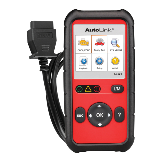
Using the Scan Tool Tool Description Figure 2-1 Product View LCD DISPLAY – displays menus and test results. RED LED – indicates there is a problem in one or more of the vehicle’s systems. The red LED is also used to show that DTCs are present. -
Page 8: Specifications
ESC BUTTON – cancels a selection (or action) from a menu or returns to the previous screen. LEFT SCROLL BUTTON – when look up DTC definitions, moves to previous character and views additional information on previous screens if DTC definition covers more than one screen; deselect all marked PID data when viewing or recording customized live data list;... -
Page 9: Accessories Included
Item Description -20℃ to 70 ℃ (-1℉ to 158℉) Storage Temp. External Power 8.0 to 18.0V power provided via vehicle battery 183 mm (7.2”) x 91 mm (3.58”) x 33 mm (1.3”) Dimensions (LxWxH) Weight 237 g (0.522 lb.) Accessories Included User Manual –... -
Page 10: Dtc Lookup
Connect the OBD II Cable to scan tool. Find DLC on vehicle. A plastic DLC cover may be found for some vehicles and you need to remove it before plugging the OBD II cable. Plug OBD II cable to the vehicle’s DLC. DTC Lookup The DTC Lookup function is used to search for definitions of DTCs stored in the DTC library and for code breaker information. -
Page 11: System Setup
If retrieved DTCs contain any manufacturer specific codes, the AutoVIN function embedded in this tool will automatically display the definition of the code. If definition could not be found, the scan tool displays “Please refer to vehicle service manual!” ... - Page 12 To enter the Setup menu From the Main Screen: Use the UP/DOWN scroll button and LEFT/RIGHT scroll button to select Setup, and press the OK button. Follow the instructions to make adjustments and settings as described in the above setup options. Figure 2-4 Sample System Setup Screen Language ...
- Page 13 Figure 2-6 Sample Configure Monitors Screen In this menu, you could configure the monitors required to test spark ignition and compression ignition, the number of monitors to pass diagnosis, and restore the default settings. Spark IGN Required Monitors From Configure Monitors screen, use the UP/DOWN scroll button to select Spark IGN Required Monitors, and press the OK button.
- Page 14 Table 2-3 Compression IGN Required Monitors √ √ √ √ FUEL √ √ √ √ HCCAT √ NCAT Allowed INC Monitors From Configure Monitors screen, use the UP/DOWN scroll button to select Allowed INC Monitors, and press the OK button. Emissions tests vary depending on the geographic or regional area in which the vehicle is registered.
- Page 15 Figure 2-7 Sample Unit of Measure Screen Press the OK button to save your selection and return to previous menu. Key Beep Set This function allows you to turn on/off the build-in speaker for key pressing. The default setting is Beep On. From System Setup screen, use the UP/DOWN scroll button to select Key Beep Set and press the OK button.
- Page 16 From System Setup screen, use the UP/DOWN scroll button to select Status Beep Set and press the OK button. From Status Beep Set menu, use the UP/DOWN scroll button to select Beep ON or Beep OFF to turn on/off the beep. Figure 2-9 Sample Status Beep Set Screen Press the OK button to save your selection and return to previous menu.
- Page 17 Look for missing spots in the red, green, blue, black and white LCD display. When completed, press the ESC button to exit. Keyboard Test The Keyboard Test function verifies if the keys are functioning properly. Use the UP/DOWN scroll button to select Keyboard Test from the Tool Self-test menu, and then press the OK button.
- Page 18 If you already have an Autel account, Sign In with your account ID and password. If you are a new member to Autel, click on the Create Autel ID button on the left side to create an ID. Enter the required information in the input fields, and click the Get Verification Code button to get a verification code for email validation.
- Page 19 Input the code in the Verification code field and complete other required fields. Read through Autel’s Terms and Conditions and click on Agree, and then click Create Autel ID at the bottom. A product registration screen will display.
- Page 20 Enter your Autel ID and password and wait for the Update window to display. If you forget your password, you may click the [Forget Password?] to link to our website and find your password back. Or you may click Sign up to create an Autel ID to continue.
- Page 21 View or Delete Programs To view the list of installed programs or to delete an installed program, please follow these steps: Click on the Installed tag entry and the page will show the list of programs installed. Select the program(s) that you would delete. ...
-
Page 22: About
The default setting is Show On. From System Setup screen, use the UP/DOWN scroll button to select Vehicle Info Show Set and press the OK button. From Vehicle Info Show Set menu, use the UP/DOWN scroll button to select Show ON or Beep OFF to turn on/off the Vehicle Info screen. Figure 2-16 Sample Key Beep Set Screen Press the OK button to save your selection and return to previous menu. -
Page 23: Vehicle Coverage
Vehicle Coverage The AutoLink AL529 OBDII/EOBD Scanner is specially designed to work with all OBD II compliant vehicles, including those equipped with next- generation protocol -- Control Area Network (CAN). It is required by EPA that all 1996 and newer vehicles (cars and light trucks) sold in the United States must be OBD II compliant and this includes all Domestic, Asian and European vehicles. - Page 24 Verify the ignition key is in the KOER position. Run the LED Test in the System Setup menu. If the scan tool did not pass this test, there is a problem with the LED lamp. Please contact Autel Tech Support or your local selling agent.
-
Page 25: Playback
Playback The Playback function allows viewing and printing of data from last test recorded by the scan tool. Review Data Use the UP/DOWN scroll button and LEFT/RIGHT scroll button to select Playback from Main Screen, and press the OK button. Select Review Data, and press the OK button. -
Page 26: Print Data
Windows-based PC or laptop with the USB cable supplied. Download the Maxi PC Suite from www.autel.com and install. Connect the scanner to computer with the USB cable supplied. Run Autel Printer software on computer. - Page 27 Select Playback function in Main Screen of the tool. In data menu screen, select Print Data and then select the data you want to print. Wait for the reviewing window to display, and then select Print function. The selected file will be uploaded to your computer. The Printer will show as below.
-
Page 28: Obdii Diagnostics
OBD II Diagnostics When more than one vehicle control module is detected by the scan tool, you will be prompted to select the module where the data may be retrieved. The most often to be selected are the Power train Control Module [PCM] and Transmission Control Module [TCM]. - Page 29 If the scan tool fails to communicate with the vehicle’s ECU (Engine Control Unit) more than three times, a “LINKING ERROR!” message shows up on the display. Verify that the ignition is ON; Check if the scan tool’s OBD II connector is securely connected to the vehicle’s DLC;...
-
Page 30: Read Codes
Figure 4-3 Sample Erase Previous Data Screen If no data is stored in the scan tool, the above prompt will not show up. If you wish to erase the data, press the OK button; if you do not want to erase the data, press ESC to exit or use LEFT/RIGHT button to select NO and press OK for Diagnostic Menu to come up. - Page 31 Use UP/DOWN scroll button to select Read Codes from Diagnostic Menu and press OK button. Figure 4-4 Sample Diagnostic Menu Use the UP/DOWN scroll button to select OBDII Codes or Enhanced Codes from the Read Codes menu and press the OK button. Figure 4-5 Sample Read Codes Screen ...
-
Page 32: Erase Codes
Figure 4-6 Sample DTC Screen If more than one DTC is found, use the LEFT/RIGHT scroll button to check all the codes. If retrieved DTCs contain any manufacturer specific or enhanced codes, the AutoVIN technology adopted by this tool will automatically display the definition of the code. -
Page 33: Live Data
Figure 4-7 Sample Erase Codes Screen If you do not want to proceed with erasing codes, press ESC button or use LEFT/RIGHT scroll button to select NO to exit. A message of “Command Cancelled!” shows up. Wait a few seconds or press any key to return to Diagnostic Menu. - Page 34 Figure 4-8 Sample Live Data Screen 1 Use the UP/DOWN scroll button to select View Data from Live Data menu and press the OK button. Figure 4-9 Sample Live Data Screen 2 View Complete Data Set To view complete set of data, use UP/DOWN scroll button to select Complete Data Set from View Data menu and press the OK button.
- Page 35 View live PIDs on the screen. Use the UP/DOWN scroll button for more PIDs if additional information is available on more than one page. Figure 4-11 Sample Complete Data Screen The number “x” to the right of the screen indicates sequence of the highlighted item.
- Page 36 Figure 4-13 Sample Custom Data Set Screen 1 Use the RIGHT button to deselect/select data parameters, and use the UP/DOWN scroll button to move up and down. Selected parameters are marked with solid squares. Figure 4-14 Sample Custom Data Set Screen 2 ...
- Page 37 Figure 4-15 Sample Custom Data Set Screen 3 Use the ESC button to return to previous menu. Record Data The Record Data function allows recording vehicle modules’ Parameter Identification (PID) data to help diagnose intermittent vehicle problems. A recording includes 5 frames of live data before trigger event and several frames after trigger event.
- Page 38 Figure 4-16 Sample Record Data Screen Use the UP/DOWN scroll button to select a trigger mode and press the OK button. Figure 4-17 Sample Pick Trigger Mode Screen If data from previously tested vehicle is not erased, data from current test will be stored in a temporary cache.
- Page 39 If you select a location marked with an asterisk (*) icon, a message prompting to overwrite old recording displays. Figure 4-19 Sample Select Memory Screen If you wish to proceed with overwriting the old recording, press the OK button; if you do not wish to overwrite it, use the LEFT/RIGHT button to select NO or press the ESC button to pick another memory location.
- Page 40 Wait for DTC to trigger recording or press OK to start recording. Drive till a DTC is detected when DTC Trigger is selected. If no DTCs are detected, press ESC to exit recording. Figure 4-22 Sample Recording Data Screen ...
- Page 41 Observe on-screen instructions. Press the OK button to continue; press the ESC button, or use LEFT/RIGHT button to select NO and press the OK button to return to Record Data menu. Use the RIGHT button select/deselect data parameters. Selected parameters are marked with solid squares. Press the OK button to confirm.
-
Page 42: View Freeze Frame Data
Use the UP/DOWN button to select the memory location marked with an asterisk (*) icon. Figure 4-24 Sample Select Memory Screen 2 If there is no recording in selected location, a message “Not Supported or Stored No Data” displays on the screen. Use the UP/DOWN button to view recorded PIDs of each frame. -
Page 43: Retrieve I/M Readiness Status
Wait a few seconds while the scan tool validates the PID MAP. If retrieved information covers more than one screen, use the DOWN scroll button, as necessary, until all the data have been shown up. Figure 4-26 Sample View Freeze Frame Screen ... - Page 44 An I/M Readiness Status result of “NO” does not necessarily indicate that the vehicle being tested will fail the state I/M inspection. For some states, one or more such monitors may be allowed to be “Not Ready” to pass the emissions inspection.
- Page 45 run and performed their self-diagnostic testing is in the allowed limit. MIL is off).There are no stored and pending DTCs. The vehicle is ready for an Emissions Test, and there is a good possibility that it can be certified. YELLOW LED –...
- Page 46 Audio Tone Interpretation The audio tone is configured according to the I/M Readiness Status. This function is invaluable when performing diagnostics and driving at the same time, or working in bright areas where LED illumination alone is not sufficient. Different audio tone with different LED light indicates different I/M Readiness Status.
- Page 47 For spark ignition engines: MIS – Misfire Monitor FUEL – Fuel System Monitor CCM – Comprehensive Component Monitor EGR – EGR System Monitor O2S – O2 Sensors Monitor CAT – Catalyst Monitor EVAP – Evaporative System Monitor ...
-
Page 48: O2 Monitor Test
If the vehicle supports readiness test of “This Drive Cycle”, a screen of the following displays. Figure 4-30 Sample This Drive Cycle Screen The LEDs and audio tone corresponding to different monitor status will be activated as below. Table 4-2 LED Light Audio Tone Beep Interval... - Page 49 The O2 Monitor Test function is not supported by vehicles which communicate using a controller area network (CAN). For O2 Monitor Test results of CAN-equipped vehicles, see On-Board Monitor Test on page 46. Use the UP/DOWN scroll button to select O2 Monitor Test from Diagnostic Menu and press OK button.
-
Page 50: On-Board Monitor Test
On-Board Monitor Test The On-Board Monitor Test is useful after servicing or after erasing a vehicle’s control module memory. The On-Board Monitor Test for non-CAN- equipped vehicles retrieves and displays test results for emission-related power train components and systems that are not continuously monitored. The On-Board Monitor Test for CAN-equipped vehicles retrieves and displays test results for emission-related power train components and systems that are and are not continuously monitored. - Page 51 Figure 4-33 Sample On-board Mon. Test Screen 1 From On-Board Mon. Test menu, use the UP/DOWN scroll button to select a test to view and press the OK button. Or, use the LEFT/RIGHT scroll button to view previous/next screen of test items. ...
-
Page 52: Component Test
NOTE If the On-Board Monitor Test failed, this monitor item will be red color. Just by the text color you may easily find out which system is at fault. Figure 4-36 Sample On-board Mon. Test Screen 4 Press ESC button to return to the previous menus. Component Test The Component Test function allows initiating a leak test for the vehicle's EVAP system. -
Page 53: View Vehicle Information
Figure 4-38 Sample Component Test Screen 2 Some vehicles do not allow scan tools to control vehicle systems or components. If the vehicle under test does not support the EVAP Leak Test, an advisory message is displayed on the screen. Figure 4-39 Sample Component Test Screen 3 Wait a few seconds or press any key to return to previous screen. - Page 54 Figure 4-40 Sample Vehicle Info. Screen 1 Wait a few seconds while the scan tool reads vehicle information. If the vehicle does not support this mode, a message shows on the display warning that the mode is not supported. From Vehicle Info.
-
Page 55: Modules Present
Modules Present The Modules Present function allows viewing of the module IDs and communication protocols for OBD2 modules in the vehicle. Use the UP/DOWN scroll button to select Modules Present from Diagnostic Menu and press OK button. View modules present with their IDs and communication protocols. Figure 4-43 Sample Modules Present Screen Press the ESC button to return to previous menu. - Page 56 Figure 4-45 Sample Code Breaker Screen Click on System Description and Quick Check to read the code information, symptoms, specifications, data/sensor information, etc. Click on General Notes to view helpful repair information of DTCs. To return to previous screen, press ESC button.
-
Page 57: Ready Test
Ready Test This function can be used as a convenient readiness test tool by automotive technicians to determine if the tested vehicle is ready for an emission test. By visual and audible indication, you will learn a vehicle’s monitors readiness. General Information Repairs to the emissions-control systems of a 1996 or newer vehicle cause the vehicle’s computer (ECU) memory to be cleared. - Page 58 Ready Test Application The purpose of this function is to indicate which of the vehicle’s monitors have run and completed their diagnosis and testing, and which ones have not yet run and completed testing and diagnosis of their designated sections of the vehicle’s emission system.
- Page 59 vehicle is ready, eliminating drive cycle guesswork and confirming readiness status. If the GREEN LED lights and two long beeps are heard, your vehicle is ready and the repair work is confirmed. If the RED LED lights, your vehicle is not ready and the repair work is unsuccessful.
- Page 60 LED and Tone Interpretation Select Ready Test from the Main Screen and the screen shows as below, including applicable monitors status, MIL state, Ignition type, DTCs (stored one and pending one). Figure 5-2 Sample I/M Readiness Screen If the scan tool is idle, it will show the result immediately. If it is busy, it will wait till the current procedure finished.
- Page 61 RED LED – your vehicle is Not Ready. Indicates that the number of Monitors supported by the vehicle which have run and performed their self-diagnostic testing is out of the allowed limit. Audio Tone Interpretation The audio tone could be configured according to the I/M Readiness Status. This function is invaluable when performing diagnostics and driving at the same time, or working in bright areas where LED illumination alone is not sufficient.
- Page 62 Compliance Information FCC COMPLIANCE This device complies with Industry Canada’s licence-exempt RSSs. Operation is subject to the following two conditions: This device may not cause harmful interference. This device must accept any interference received, including interference that may cause undesired operation. Cet appareil est conforme aux CNR exempts de licence d’Industrie Canada.
- Page 63 and on, the user is encouraged to try to correct the interference by one or more of the following measures: – Reorient or relocate the receiving antenna. – Increase the separation between the equipment and receiver. – Connect the equipment into an outlet on a circuit different from that to which the receiver is connected.
- Page 64 Limited One Year Warranty Autel Intelligent Technology Corp., Ltd. (the Company) warrants to the original retail purchaser of this Autel device that should this product or any part thereof during normal usage and under normal conditions be proven defective in material or workmanship that results in product failure within 1 year period from the date of purchase, such defect(s) will be repaired, or replaced (with new or rebuilt parts) with Proof of Purchase, at the Company’s...
- Page 65 Service and Support If you have any questions regarding the product, please contact one of our offices in your region. AUTEL NORTH AMERICA Phone: 855-AUTEL-US (855-288-3587) Monday-Friday 9am-6pm EST Website: www.autel.com Email: ussupport@autel.com...
- Page 66 Address: Office 103, Building 3845, International Business Park, Veracruz, Panamá Pací fico, Panamá AUTEL AUSTRALIA Phone: 03 9480 2978 / +61 476293327 Website: www.autel.com.au Email: sales@autel.com.au Address: 155 Islington Street, Melbourne, Collingwood, VIC For technical assistance in other markets, please contact your local selling...
Need help?
Do you have a question about the AUTOLINK AL529 and is the answer not in the manual?
Questions and answers