
Related Manuals for ELTRA CS-580A


Summary of Contents for ELTRA CS-580A
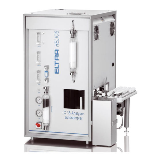
- Page 1 Operating Manual Carbon and Sulfur Analyzer CS-580A (Helios) Original © Eltra GmbH, 42781 Haan, Retsch-Allee 1-5, Germany 02.07.2014 0001...
- Page 2 Copyright © Copyright by Eltra GmbH Haan, Retsch-Allee 1-5 D-42781 Haan Federal Republic of Germany...
-
Page 4: Table Of Contents
Notes on the Service Manual ........................ 6 Explanations of the safety warnings ....................6 Installation ............................... 8 Setting check up ..........................8 Front panel illustration ........................9 Mains power connections ........................ 10 Data Interface ..........................11 Oxygen connection .......................... 12 Operation modes .......................... - Page 5 Furnace side (inside view) ....................... 46 TIC-module ............................48 Packaging ............................50 Pre-installation guide ........................... 51 Approved methodologies to which Eltra instruments conform ............52 Inorganic materials (Metals) ......................52 Organic materials (Oil, Coal, foodstuffs) ..................53 Disposal ..............................54 Index ..............................
-
Page 6: Notes On The Service Manual
Notes on the Service Manual 1 Notes on the Service Manual 1.1 Explanations of the safety warnings In this Operating Manual we give you the following safety warnings Mortal injury may result from failing to heed these safety warnings. We give you the following warnings and corresponding content. - Page 7 Notes on the Service Manual NOTICE Nature of the property damage Source of property damage – Possible consequences if the instructions are not observed. • Instructions on how the dangers are to be avoided. We also use the following signal word in the text or in the instructions on action to be taken: NOTICE...
-
Page 8: Installation
Installation 2 Installation 2.1 Setting check up Since the analyser weighs about 90 kg it should be placed on a suitably stable surface. Due to the balance, the platform should be as free of vibration as possible. The loader is attached to the right side of the analyser. There are no strong recommendations where to place the balance, PC, display and printer. -
Page 9: Front Panel Illustration
Installation 2.2 Front panel illustration 1 2 0 L a n c e 3 0 0 2 0 0 1 0 0 C a r r i e r 3 0 0 2 0 0 1 0 0 I n l e t I n l e t G a s C / S - A n a l y s e r... -
Page 10: Mains Power Connections
Installation 2.3 Mains power connections Since the infrared cell requires about 1 hour for reaching a stable operating temperature, it is advisable to first connect the analyzer to the mains power and to set the mains power switch to position 1 before further installation work is carried out. -
Page 11: Data Interface
24V connector Digital input/output signals Autoloader connection Regulating valve (not relevant for CS-580A) When all units are connected to the mains power, then interface connections can be made. The required interface cables are included in the scope of supply. The supplied additional devices have been already adapted to the interfaces when the analyzers are taken into operation in our company. -
Page 12: Oxygen Connection
Installation Please note: As the balance transfers the weight to the PC, its serial interface must be programmed. This is important, if you use a balance, which was not ordered with the analyzer. NOTICE For all instructions for using the PC software refer to the Help-function of the software. - Page 13 Installation Off. The analyzer is completely switched off. Standby. The thermostatic control of the IR-cell is switched on. The furnace is switched off and the gas flow is disabled. Communication with the PC is possible. Furnace on. Furnace is switched on, but the gas flow remains disabled.
-
Page 14: Adjusting The Gas Flow
Installation 2.7 Adjusting the gas flow 1 2 0 L a n c e 3 0 0 2 0 0 1 0 0 C a r r i e r 3 0 0 2 0 0 1 0 0 I n l e t I n l e t G a s C / S - A n a l y s e r... -
Page 15: Temperature Adjustment
2.8 Temperature adjustment The furnace temperature is PC-controlled. The CS-580A is delivered with 1350°C set temperature saved in a software profile. After switching on the instrument at position 2 and starting of the UNI-software, the heating up to the set temperature is started automatically. (The cable connection between instrument and PC is in the scope of supply). -
Page 16: Bios-Configuration
Installation Fig. 6: Window Configuration – Heater - Preheating The value shows the chosen heating rate in °C/min. (The preheating function is switched off by entering 0 in this place. Then, the heating occurs with maximum speed after start of the UNI-software.) Save your entry with Enter. -
Page 17: Analysis
PC-screen and saved in the database of the software. A series of analyses can be run with the CS-580A (Helios) analyzer. To do this, repeat steps 1 to 7 for every sample in the series, while each crucible is placed as next after the last one placed on the loader. -
Page 18: Procedure Of Carrying Out Analyses With Manual Loading Of The Sample
3.1.2 Procedure of carrying out analyses with manual loading of the sample Although the CS-580A (Helios) is equipped with an autoloader and normally analyses are carried out using this autoloader, it is possible to load the sample manually for analysis. -
Page 19: Tic-Determination
Analysis 3.2 TIC-determination 3.2.1 TIC-module Due to the modular design of the CS-580 (Helios), the analyzer can be upgraded by a module for Total Inorganic Carbon (TIC) without further modification. For the TIC determination, the sample is treated with acid in the TIC module. 3.2.2 TIC analysis The sample is treated with acid in an Erlenmeyer flask inside the TIC-module. -
Page 20: Tic-Module Installation
Analysis CO2 outlet Glass distributor Connection to the furnace Acid supply 50 ml glass flask Heater with magnetic stirrer Elevator with variable height Acid Furnace Analyzer Moisture trap TIC/TC toggle 3.2.3 TIC-module installation The TIC module is placed next to the analyzer. Connect the mains power plug to a power socket. -
Page 21: Tic-Module Operation Procedure
Analysis Fig. 8: Scheme CS580 with TIC module 3.2.4 TIC-module Operation procedure Place the empty glass flask (6) on the balance. Press tare. Put the sample into the flask and enter the weight into the analyzer (F4- button). When powder sample sticks in the flask neck, add 2 ml of water (but don't transfer the weight of the water!) Place a magnetic stirrer into the flask and attach the flask to the distributor (3). -
Page 22: Applications
Analysis The table below shows approximate sample weight and acid volume depending on the expected TIC content in the sample. TIC-content Sample weight Acid >5 % 100 - 200 mg 2×2 ml 1-5 % 200 - 500 mg 3×2 ml <1 % 1000 - 2000 mg 3×3 ml... - Page 23 Analysis Weight: 350mg Set the minimum analysis time to 50s. Set the comparator level to 20mV.
-
Page 24: Maintenance
Maintenance 4 Maintenance 4.1 General information – Replace the magnesium perchlorate of the moisture trap of the furnace after 150 analyses. See chapter “Front panel illustration” and “Filling the reagent tubes”. In order to save material, replace first the upper half. The next time replace the whole of the magnesium perchlorate. - Page 25 Maintenance The O-rings are only replaced when they can no longer adequately seal, due to a damage or age. When removing the old O-rings, be ensure that the sealing areas of the fittings are not damaged. NOTICE When replacing O-rings, never grease the new O-rings before installation. Otherwise, the O-rings will turn with the glass tube when trying to remove it.
-
Page 26: Reagent Tubes Filling
Maintenance 4.2 Reagent tubes filling 4.2.1 Reagent tube replacing Fig. 9: Installalling the reagent tubes The reagent tubes are first lifted and then swung to one side, detached diagonally downwards and emptied. Remark The dimensions for filling the glass tubes given in the schematics of chapter ”Reagent tubes filling”... -
Page 27: Filling Quantities
Maintenance Before the reagent tubes are fitted, the O-rings and the inner ends of the tubes should be lubricated with high vacuum silicon grease. 4.2.2 Filling quantities As different samples can contain different amounts of moisture, it is hard to give a precise number of analyses that can be made before the content of the reagent tubes should be replaced. - Page 28 Maintenance 1 2 0 L a n c e 3 0 0 2 0 0 1 0 0 C a r r i e r 3 0 0 2 0 0 1 0 0 I n l e t I n l e t G a s C / S - A n a l y s e r A u t o s a m p l e r...
-
Page 29: Moisture Trap Replacing (Furnace)
Maintenance 4.3 Moisture trap replacing (furnace) Fig. 10: Replacement of moisture trap Turn both screws (1) counter clockwise, until the ring (3) touches the part (2). Lift the glass tube (5) upwards, tilt it to the side and pull downwards. Replace the magnesium perchlorate (Anhydrone). -
Page 30: Dust Filter Cartridge Replacing
Maintenance Fig. 11: Preparation of moisture trap O-rings 4.5 Dust filter cartridge replacing The dust filter cartridge filters smallest dust particles from the combustion gases. Its saturation depends on the sample material and its combustion characteristics. The filtering material of a new cartridge is white. Replace the dust filter cartridge when the filtering material shows coloration, or at least every 500 analysis. -
Page 31: Combustion Tube Replacing
Maintenance Take care for the cartridge body to have the smaller diameter up and the bigger down. 4.6 Combustion tube replacing DANGER G0002 Mortal danger from electric shock Exposed power contacts - High Voltage - An electric shock can cause injuries in the form of burns and cardiac arrhythmia, respiratory arrest or cardiac arrest. -
Page 32: Lance Replacing
Maintenance to lift it in straight vertical direction to avoid collision of the lance (11) with the combustion tube (12). If the assembly is not free to be easily lifted, slightly tilt it carefully in different directions until it becomes free. •... -
Page 33: Heating Elements Replacing
Maintenance • Remove the 4 screws (8) which hold the assembly (6/7) on the furnace. • Lift the assembly (6/7) in straight vertical direction. • Unscrew the four screws and nuts which hold the parts (6) and (7) together. • Replace the lance (11) •... - Page 34 Maintenance • Loose the four nuts (13) and remove the two double clamps (14). • Pull up the four heating elements (15) • Reinstall in reverse order using new heating elements. Remark Install the clamps (14) in a position which allows the heating elements to move at least 5 mm in vertical (axial) direction.
-
Page 35: Function Description
Function description 5 Function description 5.1 Measuring principle The measuring method is based on the principle of sample combustion and the analysis of the combustion gases, using infrared absorption. A wide variety of sample materials in various forms is possible, like powders, grains, chips, solid pieces and also some materials in liquid form. -
Page 36: Gas Flow System
Function description 5.2 Gas flow system Fig. 13: Gasflow (Scheme) Carrier gas inlet Dust filter cartridge Pressure regulator Pressure regulator Oxygen stop valve (power switch Flow adjustment restrictor control) Pressure switch and pressure gauge Gas flow meter Oxygen stop valve (software Infrared cell controlled) Flow adjustment restrictor... - Page 37 Function description The analyzer is operated with pure oxygen. A purity of 99.5% is sufficient. It is normally available in steel bottles. CO2 and H2O impurities in the oxygen are trapped in the trap (8). The upper half of the trap is filled with CO2 absorber and the lower half with moisture absorber.
- Page 38 Function description Fig. 14: Gas flow...
-
Page 39: Infrared Cell
Function description 5.3 Infrared cell The measuring principle is based on the infrared radiation absorbing properties of many gases. Each of these gases absorbs specific characteristic spectral wavelengths of infrared radiation. The absorption spectrum is determined by the number, configuration and type of the atoms in the gas molecules. Fig. -
Page 40: Micro-Controller Unit And Pc Software
Function description infrared cell rack is temperature controlled so that the sample gas flowing through it is kept at a constant temperature. 5.4 Micro-controller unit and PC Software The microcontroller unit (MCU) contains all components for signal processing and control sequencing. It is working under the control of the PC software, collecting and processing signals and sending data to the PC-software. -
Page 41: Ordering Numbers
Ordering numbers 6 Ordering numbers 6.1 Analyszer front view Fig. 10: CS-580A front view Part Nr. Description 09090 Reagent tube 09092 Alternative reagent tube with bigger capacity 09093 Alternative reagent tube with maximum capacity 11170 Dust filter cartridge 11480 Adjustable restrictor... -
Page 42: Rear Side (Outside View)
Ordering numbers Pressure gauge 2.5 bar for oxygen 72010 Pressure gauge 10 bar for compressed air 72020 Mains power switch 78017 6.2 Rear side (outside view) Fig. 11: Rear side inside view Part Nr. Description 14618 Microcontroller board UNI 1.4 15268 Pump control boart PC1 35490... -
Page 43: Bottom (Outside View)
Ordering numbers 60552 Adjustable restrictor 77032 Circuit breaker 77140 Mains power filter 77145 Mains power filter 77460 Switch 6.3 Bottom (outside view) Fig. 12: Bottom view Part Nr. Description 11035 Cooling fan 11492 Oxygen pressure regulator... -
Page 44: Left Side View (Inside)
Ordering numbers 6.4 Left side view (inside) 16114 11490 36914 36284 36284 11480 26320 PTC2 36915 78072 77051 RC-Bu1 77052 35533 35537 60353(Sensor) 18468 Microcontroller board UNI 2.1 35526 Part No.18468 Pump control 24VDC Analog I/O Digital I/O 35779 MD50 35779 06441 11492... - Page 45 Ordering numbers 11480 Adjustable restrictor 11490 Pressure regulator 11492 Oxygen pressure regulator 15083 Flow meter 15 L/h 16114 Power supply 18468 Microcontroller board UNI2 26320 Insulator 35536 2/2-way valve 24VDC 35779 Power/temperature control cable 36284 Heating element connector 36798 Transformer 36904 Temperature control board TH 44 36914...
-
Page 46: Furnace Side (Inside View)
Ordering numbers 6.5 Furnace side (inside view) Fig. 13: Furnace inside view (inside) Part Nr. Description 35408 Lower plate insulation 35462 Upper plate 35512 Ceramic plate 35540 Combustion tube 35541 Ceramic lance 35542 Pedestal 36284 Heating element connector 36289 Heating element clamp... - Page 47 Ordering numbers 70150 O-ring 70427 O-ring 70428 O-ring 77501 Heating elements, 4pcs 77505 Ceramic spacer 90150 Crucible...
-
Page 48: Tic-Module
Ordering numbers 6.6 TIC-module Fig. 17: TIC-module [35543-9008]... - Page 49 Ordering numbers Glass stopper (connection to the analyzer) 38225 Upper moisture trap connector 11042 O-ring 9*3 70230 Moisture trap 11064 Glass distributor 38200 50 ml glass flask 90090 Heater with magnetic stirrer 71070 Support with variable height 38400 O-ring 9*3 70230 Lower moisture trap connector 11045...
-
Page 50: Packaging
Ordering numbers 6.7 Packaging Fig. 14: Packing Before packing, the analyzer must be wrapped in plastic foil to protect it from moisture and dust, and then be placed in a wooden case. The wrapped analyzer should be surrounded by a layer of plastic foam (or at least chips) of at least 10cm, in order to avoid any damage during transport. -
Page 51: Pre-Installation Guide
Pre-installation guide 7 Pre-installation guide Following requirements apply, when installing the analyzer: Carrier gas Oxygen 99.95 % pure; 2 - 4bar (30 - 60psi) Mains power supply 230VAC ±10%, 50/60Hz; 20A fuse CEE-Plug 230V, 32A Analyzer dimension 550 x 970 x 600mm Loader dimension 850 x 350 x 450mm (depending on version) Analyser weight... -
Page 52: Approved Methodologies To Which Eltra Instruments Conform
Approved methodologies to which Eltra instruments conform 8 Approved methodologies to which Eltra instruments conform 8.1 Inorganic materials (Metals) Norm Elements Materials Instruments CS-800 DIN EN ISO 9556:2002-04 Steel and Iron CS-2000 ISO 4935:1989 CS-800 Steel and Iron DIN EN 24935:1992-07... -
Page 53: Organic Materials (Oil, Coal, Foodstuffs)
Approved methodologies to which Eltra instruments conform 8.2 Organic materials (Oil, Coal, foodstuffs) Norm Elements Materials Instruments ASTM D 1552:2008 Oil and Petrolium Products CS-580 CS-2000 ASTM D 4239:2013; Coal and Coke CS-580 CS-2000 ASTM D 5016:2008 Coal and Coke Ash... -
Page 54: Disposal
Disposal 9 Disposal Please observe the respective statutory requirements with respect to disposal. Information on disposal of electrical and electronic machines in the European Community. Within the European Community the disposal of electrically operated devices is regulated by national provisions that are based on the EU Directive 2002/96/EC on Waste Electrical and Electronic Equipment (WEEE). -
Page 55: Index
Gas connections 50 Analyszer front view 40 Gas flow 37 Anhydrone 27 Gas flow system 35 Applications 21 Gasflow Approved methodologies to which Eltra instruments scheme 35 conform 51 Arrangement Suggestion 8 General information 23 Glass wool 27 BIOS-configuration 16... - Page 56 Reagent tubes filling 25 Rear side (outside view) 41 Rear side inside view 41 Magnesiumperchlorat 27 rear side of device 12 Mains power connections 10 Rearview Maintenance 23 Mains power connections 10 MCU 39 measuring method 34 Measuring principle 34 Microcontroller board 11 Micro-controller unit and PC Software 39 Safety warnings 6...
- Page 60 Copyright ® Copyright by Eltra GmbH Haan, Retsch-Allee 1-5 D-42781 Haan Federal Republic of Germany...
Need help?
Do you have a question about the CS-580A and is the answer not in the manual?
Questions and answers