Table of Contents
Advertisement
Available languages
Available languages
Quick Links
User Manual
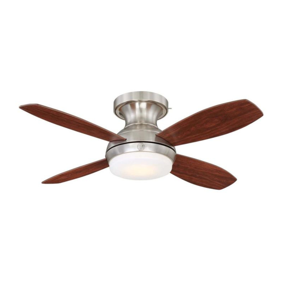
Kinsey LED Ceiling Fan
1.12 m (44 in.)
MODEL: 20444 Brushed Nickel
MODEL: 20505 Bronze
MODEL: 20611 White
120V 60Hz, MADE IN CHINA
Customer Assistance
1-866-885-4649
customerservice@skyplug.com
Contact a qualified electrician or call the Customer Care Service Team at 1-866-885-4649
Note: Installation videos for GE Branded fans with SkyPlug technology
can be viewed and downloaded on www.gelightingandfans.com
Customer Service hours of operation are 9:00AM-5:00PM EST -Monday-Friday
customerservice@skyplug.com
Register your GE Branded fan for warranty coverage on
www.gelightingandfans.com
NV03-20180710
Advertisement
Table of Contents

Related Manuals for GE 20444


Summary of Contents for GE 20444
- Page 1 Contact a qualified electrician or call the Customer Care Service Team at 1-866-885-4649 Customer Service hours of operation are 9:00AM-5:00PM EST -Monday-Friday customerservice@skyplug.com Register your GE Branded fan for warranty coverage on www.gelightingandfans.com Note: Installation videos for GE Branded fans with SkyPlug technology can be viewed and downloaded on www.gelightingandfans.com NV03-20180710...
-
Page 2: Safety Rules
Safety Rules READ AND SAVE THESE INSTRUCTIONS 1. To reduce the risk of electric shock, ensure electricity has WARNING: To reduce the risk of personal injury, do not bend the been turned off at the circuit breaker or fuse box before blade arms (also referred to as beginning. - Page 3 SAFETY TIPS 1. Before working on a circuit , go to the main service panel and remove the fuse or turn off the breaker that controls that circuit . 2. Tape a sign to the panel warning others to leave the circuit alone while you work.
- Page 4 Tools Needed (Not Supplied) Required Flathead Screwdriver Philips Screwdriver Safety Glasses (#1 screwhead recommended) Step Ladder Wire Stripper Soft Cloth...
-
Page 5: Hardware Included
Hardware Included ATTENTION: Parts are not to scale. Carefully unpack and identify each part to make sure you have everything ready for installation. Lay out each part on a clean area such as a table or floor. NOTE: +1 = Extra quantity Check to make sure you have the following: supplied for future use if needed. -
Page 6: Package Contents
4 mm rubber washer, mounting screw and flat washer) (Preassembled to canopy of fan motor assembly) (Pre-assembled to bottom of fan motor assembly) Light Kit Mounting Screw (Pre-assembled to mounting plate) Register your GE Branded fan for warranty coverage on www.gelightingandfans.com... - Page 7 Fan Installation Drawing SkyReceptacle Receptacle Slot SkyPlug Mounting Screw Cover Plate Push Lever Receiver Register your GE Branded fan for warranty coverage on www.gelightingandfans.com...
- Page 8 SkyReceptacle Typical Wire Configurations TYPICAL WIRE CONFIGURATIONS: IMPORTANT: For remote control fans, L1 is the only active live /hot terminal. The hot/live wire from house supply must be inserted into L1 terminal for the fan to operate. Black (Live) White WIRING DIAGRAM #1: Typical Wiring Configuration...
- Page 9 SkyReceptacle Installation Important: Always install SkyReceptacle with rubber washers to avoid a gap or uneven surface, and to ensure proper placement of receptacle on the ceiling. 0-1.5mm Gap 0-1.5mm 4mm rubber washer (pre-installed) If your box is flush with the ceiling, or recessed less than 1.5mm, install with 4mm rubber washers.
- Page 10 SkyReceptacle Installation 1/2"/12.7mm Terminal’s Bottom view Outlet Box on Sky Receptacle (not Supplied) Receptacle Note : If you do not have standard wiring configurations, please contact a qualified electrician, or call customer Insert wires into terminal, tighten service 1-866-885-4649. screw to secure wires. Screw torque 6.3 lb-in.
- Page 11 SkyReceptacle Installation Rubber Washer Using the rubber washer when installing receptacle ensures proper placement of the receptacle on the ceiling. We recommend using the rubber washers in all installations. Install cover plate if supplied (not provided on all models)
-
Page 12: Fan Installation
Fan Installation There are two options to install the fan: 1) ASSEMBLY ON CEILING - follow steps 4 - 12. 2) ASSEMBLE ON FLOOR - follow steps 9 - 12 to first assemble blades and light kit to fan while on floor, and then steps 4 - 8 to install fully assembled fan onto ceiling. - Page 13 Fan Installation Lift fan, press up on push lever. IMPORTANT: For proper moun ng, the SkyPlug and SkyReceptacle need to be lined up in a “+” formation. Line up SkyPlug to SkyReceptacle mounted in ceiling. Insert SkyPlug into SkyReceptacle (Keep push lever pushed up while inserting).
- Page 14 Fan Installation IMPORTANT : SkyPlug must be fully engaged into SkyReceptacle. Once plug is fully inserted, let go of push lever while supporting fan. “Click” sound IMPORTANT : Push lever must be in DOWN position once installed. Push up on fan to lock plug into receptacle (listen for locking “click”). Turn fan to the right (counter clockwise) to engage into slots and activate the final locking mechanism.
- Page 15 Fan Installation Once installed, tighten all 4 screws. Reinstall the trim ring, being careful not to depress the push lever. Install blades.
- Page 16 Fan Installation Note: Loosen 2 and remove 1 of the 3 mounting plate screws located at the bottom of motor assembly. Remove 1 Loosen 2 Install Mounting plate. Remove 1 Loosen 2 Note: Loosen 2 and remove 1 of the 3 light kit mounting screws on the mounting plate.
-
Page 17: Fan Operation
Installing the Transmitter Holder Select a location to install your transmitter holder. Attach the transmitter holder with the two short wood screws provided. Fan Operation Reverse Function Summer Reverse Switch Winter Fan Operation Using Standard Wall Switches -Only one standard wall switch can be used to turn the fan ON/OFF. The fan light and fan speed must be controlled with the included remote control. -
Page 18: Remote Control
Remote Control Operate Fan Using Transmitter Code Pre-set by Factory ( Keep Switch Placed In Unlock Position ) Unlock Position Step 1. Restore power to ceiling fan. Step 2. Install two 1.5-volt AAA batteries provided. Step 3. Press the “ ”... - Page 19 Remote Control REMOTE FUNCTIONS IMPORTANT: If the remote control is not operating correctly, please follow the steps on page 17 for pairing. Use the corner of the battery cover to press the "Sync" button for syncing function. Operation indicator Low speed Medium speed High speed Power ON/OFF...
- Page 20 Blade Wobble Balancing Not OK Y 3mm / ⅛in. < Y 3mm / ⅛in. Not OK >...
-
Page 21: Maintenance
Maintenance WARNING: Make sure the power is PRODUCT MAINTENANCE turned off at the electrical panel box before you attempt any repairs. Suggestions to help maintain your fan Because of the fan’s natural movement , some connections NOTE: To avoid personal injury or may become loose. -
Page 22: Troubleshooting
Troubleshooting CAUTION: Switch off power supply before carrying out any of these checks. 1.SkyPlug will not insert into SkyReceptacle: -Add rubber washers between J-box and SkyReceptacle. See Page 10 step 3. -Make sure you removed the disposable rubber inserts (page 11). -Watch installation video on www.gelightingandfans.com 2.Fan will not start: -Check main and branch circuit fuses or breakers. - Page 23 Contacte a un electricista calificado o llame al Equipo del Servicio al Cliente Horas de operación del Servicio al Cliente son de 9:00AM-5:00PM Hora Estándar del Este-Lunes-Viernes Customerservice@skyplug.com Registre la garantia de su ventilador GE en nuestra página www.gelightingandfans.com Nota: Videos de instalación para ventiladores marca GE con tecnología SkyPlug se pueden encontrar y bajar en www.gelightingandfans.com...
- Page 24 Para su seguridad LEA Y GUARDE ESTAS INSTRUCCIONES ADVERTENCIA: Para reducir el riesgo de lesiones personales, no 1. Para reducir el riesgo de descarga eléctrica, asegúrese de que doble los brazos de las aspas la electricidad se haya apagado en el disyuntor o caja de fusibles (también conocidos como bridas), al antes de comenzar.
- Page 25 Guías Básicas Para Trabajar Con Electricidad Consejos de Seguridad 1. Antes de trabajar en un circuito, vaya al panel de servicio principal y retire el fusible o active el disyuntor que controla ese circuito. 2. Pegue una señal en el panel que advierta a otras personas que se alejen del circuito mientras usted trabaja.
- Page 26 Herramientas Necesarias (No Suministradas) Requerido Destornillador de Destornillador Philips Gafas de Seguridad Cabeza Plana (Se recomienda un Destornillador #1) Escalera Pelador de Cables Paño suave...
-
Page 27: Herramientas Incluidas
Herramientas Incluidas Desempaque cuidadosamente e identi que cada pieza para ATENCIÓN: Las piezas no están a escala. asegurarse de que esté todo listo para la instalación. Coloque cada pieza sobre una super cie despejada, como una mesa o NOTA: +1 = Cantidad extra provista el piso. -
Page 28: Contenido Del Paquete
Tornillo plato de montaje (Pre-ensamblado a la parte inferior) del motor del ventilador) Tornillo del juego de luz ( Pre- ensamblado a al plato de montaje) Registre la garantia de su ventilador GE en nuestra página www.gelightingandfans.com... - Page 29 Conjunto del motor Aspa Arandela de fibra Tornillo del aspa Plato de montaje Tornillo del plato de montaje Conjunto de luz LED Tornillo del conjunto de luz Campana de vidrio Registre la garantia de su ventilador GE en nuestra página www.gelightingandfans.com...
- Page 30 Configuraciones Típicas de Cableado del Receptáculo Sky CONFIGURACIONES TÍPICAS DE CABLEADO: IMPORTANTE: Para ventiladores con control remoto, L1 es el único terminal activo. El cable con corriente de suministro de la casa debe insertarse en la terminal L1 para que el ventilador funcione. Negro (Vivo) Blanco DIAGRAMA DE CABLEADO #1...
- Page 31 Instalación del Receptáculo Sky Importante: Siempre use las arandelas de goma cuando este instalando el receptor. Esto ayudara a asegurar que el ventilador se conecte correctamente. Espacio de 0-1,5mm 0-1.5mm Arandela de goma de 4mm (Pre-ensamblado) Si su caja esta al ras con el techo o empotrada a menos de 1.5mm, instale las arandelas de goma de 4mm. Arandela de goma de 4mm Espacio de 1.5-3mm 1.5-3mm...
- Page 32 Instalación del Receptáculo Sky 1/2 pulgadas/12,7 mm Vista de debajo de los Caja Eléctrica (no terminales del receptáculo suministrada) Receptáculo Nota: Si usted no tiene una configuración Inserte los cables en los terminales, estándar en su cableado, por favor contacte apriete los tornillos para asegurar los un electricista o llame a Servicio al Cliente al cables.
- Page 33 Instalación del Receptáculo Sky Arandela de Goma Usando la arandela de goma cuando instale los receptáculos permite una colocación apropiada del receptáculo en el techo. Recomendamos el uso de las arandelas de goma en todas las instalaciones. Instale la cubierta si esta suministrada (No se suministra con todos los modelos)
- Page 34 Instalación del ventilador Hay dos opciones para instalar su ventilador: 1) Para ensamblar en el techo siga los pasos 4 -12 2) Para ensamblar en el piso – siga los pasos 9-12 para primero ensamblar las aspas y el kit de luz al ventilador mientras esta en el piso y luego los pasos 4-8 para instalar el ventilador ensamblado al techo.
- Page 35 Instalación del ventilador Levante el ventilador y presione hacia arriba la palanca de empuje. IMPORTANTE: Para un montaje correcto, SkyPlug y SkyReceptacle deben estar alineados en forma de “+”. Alinee Skyplug con el SkyReceptacle montado en el techo. Introduzca Skyplug en el SkyReceptacle (mantenga la palanca de empuje hacia arriba durante la inserción).
- Page 36 Instalación del ventilador IMPORTANTE: Skyplug debe estar totalmente acoplado en el receptáculo Una vez que el dispositivo esté totalmente introducido, suelte la palanca de empuje mientras sostiene el ventilador. Sonido de «clic» IMPORTANTE : La palanca de empuje debe estar en la posición baja una vez completada la instalación Empuje hacia arriba el ventilador para bloquear el dispositivo en el receptáculo (hasta escuchar el «clic»...
- Page 37 Instalación del ventilador Una vez instalado, apriete los 4 tornillos. Reinstale el anillo del borde nuevamente, teniendo cuidado de no presionar la palanca de presión. Instale las aspas del ventilador.
- Page 38 Instalación del ventilador Nota: Afloje 2 y retire 1 de los 3 tornillos de la placa de montaje ubicados en la parte inferior del motor primero. Retire 1 Afloje 2 Instale el plato de montaje. Retire 1 Afloje 2 Nota: Afloje 2 y retire 1 de los 3 tornillos de montaje del kit de luz en la placa de montaje...
- Page 39 Instalación del Soporte de Transmisor Seleccione una ubicación para instalar el soporte del transmisor. Fije el del transmisor con los dos tornillos de madera suministrados. soporte Operacion del Ventilador Función de Reversa Verano Interruptor de Reversa Invierno Funcionamiento del Ventilador utilizando interruptores de pared estándar -Solo un interruptor de pared estándar se puede usar para prender y apagar el ventilador.
-
Page 40: Control Remoto
Control Remoto Opere el Ventilador Usando el Código de Transmisión Pre Instalado de Posición de desbloqueo Fábrica ( Mantener el interruptor colocado en posición de desbloqueo ) Paso 1. Restablezca la electricidad del ventilador. Paso 2. Instale dos baterías AAA de 1,5 -vatios provistas. Paso 3. - Page 41 Control Remoto FUNCIONES DEL CONTROL REMOTO IMPORTANTE: Si el control remoto no funciona correctamente, favor de seguir las instrucciones en la página 17 para el emparejamiento del interruptor. Use la esquina de la cubierta de las baterías para presionar el botón "Sync" para la función de emparejamiento.
- Page 42 Balanceo de las aspas No OK Y 3mm / ⅛ pulgadas < Y 3mm / ⅛ pulgadas > No OK...
-
Page 43: Mantenimiento
Mantenimiento MANTENIMIENTO DEL PRODUCTO * ATENCION: Asegúrese que la electricidad está apagada en el panel * Sugerencias para ayudarle a mantener su ventilador * de control antes de realizar ningún Producto del movimiento natural del ventilador, algunas de las arreglo.* conexiones se podrán aflojar. -
Page 44: Solución De Problemas
Solución de Problemas CUIDADO: Apague la electricidad antes de realizar los siguientes procedimientos 1.EL Skyplug no se insertará en el Receptor: -Agregue arandelas de goma entre el J-box y el Receptor. Vea la página 10 paso 3. -Asegúrese de quitar las inserciones de goma desechables (página 11).