Advertisement
DESCRIPTION
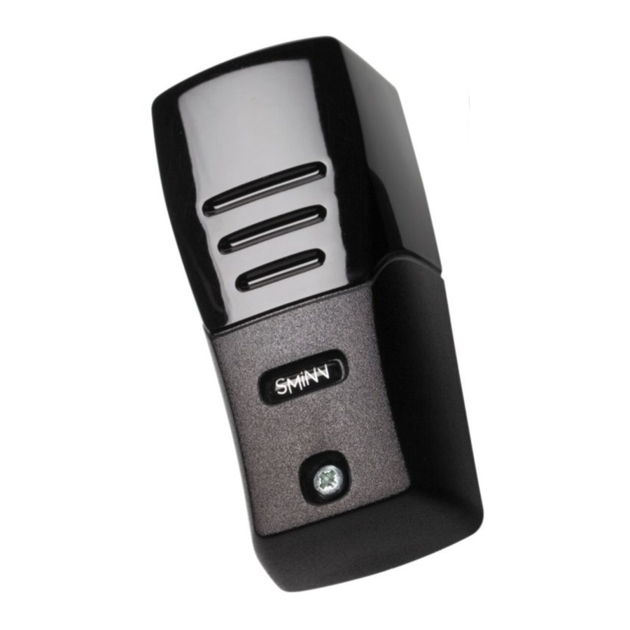
SMINN'S FC330 light barrier is composed by a RX receiver and a TX emitter that can be powered with a 3V6 DC battery.
Devices that are built using high quality materials and components and the latest technology. They are made taking into account the current regulations for usage in residential, commercial and light industry environments.
Figures
Fig. 1
 3 different positions of the lens. 180º horizontal rotation.
Fig. 2
Jumper configuration
 |  | ||
| Feature - Device | Jumper | ON | OFF |
| Gain - RX | J1 (RX) | Normal | High |
| Frequency - TX | J2 | Fast | Slow |
| Resistive Security Edge - TX | J3 (TX) | Not connected | Connected |
NOTE: The fast transmission mode (J2 = ON) halves the battery life. In slow mode (J2 = OFF) batteries can last up to 2 years depending on temperature, humidity and initial charge.
Fig. 3

Fig. 4

Placement
Fig. 5

Security Edge connection
Fig. 6

- PC front case (UV filter)
- Wall sealing O-ring
- Case sealing O-ring
- PA - FG Base
- Wall plug
- Wall screw
- Jumpers
- Lithium batteries
- Front case screw
Fig. 7

Light barrier terminal blocks.
OPERATION
Once the light barrier is correctly installed, the emitter sends a beam of infrared light modulated by pulses to the receiver, setting up a safety barrier. Each time this barrier is blocked, the receiver activates the internal red led and activates the alarm relay. All regulations on security of the installation must be strictly observed.
APPLICATIONS
The FC330 light barrier has been developed for protection in automatic doors, barriers and blinds. Also for access detection in alarm systems and traffic control.
INSTALLATION
Check the integrity of the product to be installed.
All the safety regulations associated with the installation to be carried out must be strictly observed.
- Place it away from heat sources, humidity or excessive radiation and to a minimum height of 30-40 cm from the floor, preventing reflection problems with the light beam.
THE MANUFACTURER IS NOT RESPONSIBLE OF THE DAMAGE CAUSED BY AN INCORRECT INSTALLATION OR IMPROPER OR CARELESS USE. - Avoid GASES or INFLAMMABLE PRODUCTS, as they are a serious danger for security in electric installations.
- Place emitter and receiver one in front the other, in the same axis and the same height. The receiver includes a red LED to make alignment easier and, once the system is powered, to indicate when there is no visibility between the emitter and receiver.
- Select the operating distance with the Jumper J1 placed in the receiver. See Fig.7
| Jumper J1 | ON | Distance < 15 m |
| Jumper J1 | OFF | Distance > 15 m (maximum range) |
NOTE: the operating distance can be reduced because of external, adverse conditions such as dust, excess of light, rain, fog, etc.
The emitter is ready to operate with a 2.4 / 2.8Ah 3.6V Lithium battery AA type or with a 12/24V AC/DC power supply applied to terminals 1 and 2.
- Battery powered
To increase battery life (2 years) you can adjust the frequency modulation using the J2 jumper. See Fig. 7Jumper J2 ON Fast mode Jumper J2 OFF Slow mode - External power supply
The emitter will set the frequency modulation to continuous mode when powered with a 12/24V AC/DC power supply, achieving more range regardless of the J2 jumper (Fig. 7).
Safety edge control
It is possible to connect an 8K2 safety edge assembled on the mobile gate leaf to the terminals 4 and 5. The emitter checks the edge continuously, interrupting the infrared beam when pressed and activating the security relay in the receiver. If we do not connect the safety edge, Jumper J3 must be connected. See Fig. 7.
Safety contact control
The emitter is equipped with a safety NC input in terminals 2 and 3 that deactivates the transmission of the infrared beam when that contact is opened, putting the transmitter in standby mode. If we do not connect this input, Jumper J1 (TX) must be connected. See Fig. 7.
OPERATION VERIFICATION
To verify that the light barrier is operating, interrupt the beam of light and check that the red led and the relay activate in the receiver. Without interrupting the beam and with both emitter and receiver aligned, the led must be off. With the beam interrupted or with the emitter or receiver not aligned, the red led must be on and the relay must activate.
MAINTENANCE
FC330 light barriers do not require any special care, but it is necessary to check their condition from time to time, clean the external casing of dust and dirt making sure it has a nice appearance and operates correctly, contacting a technician if there is any anomaly.
If the light barrier is battery powered, a routine of battery maintenance, checking and replacement every 2 years should be followed to guarantee the system will keep working perfectly.
The Lithium battery (Lithium-thionyl chloride Li-SOCl2) that supplies power to the transmitter is an industrial range (-55ºC / +85ºC) 3V6 AA of 2000 up to 2700 mAh. It is recommended to replace it with a battery of the same kind and quality.
UNDER NO CIRCUMSTANCE IT SHOULD BE DISPOSED WITH THE COMMON WASTE
Note: dead batteries contain pollutant substances and they should be handed in collection points for this kind of products according to the current regulations.
WARRANTY
This product has undergone a complete TEST during its manufacturing process that guarantees its reliability and proper operation.
The manufacturer provides 24 months of warranty to the product from the date printed in the product and against any anomaly that it may present in its appearance or operation.
Any damage caused by third parties, natural causes (flooding, fire, lightning, etc), arising from improper handling or installation, vandalism or any other cause non attributable to the manufacturer will void the warranty.
The warranty only covers repairs or replacement of the damaged device.
Any expenses derived from assembling, travelling, transport, natural wear of parts, etc., and, in general, any expenses that are not part of the repairs or replacement of the damaged element of the system are excluded.
The installer/provider will ask the manufacturer for an RMA number or authorization for transport of the system in warranty. Without this previous requisite, the manufacturer will not be able neither to process nor provide warranty service.

This product must be used in installations which has been conceived for, considering any other as improper use. The packaging and wrapping MUST NOT be dumped in the environment. Keep products, packaging, wrapping, documentation, etc., out of the reach of children.
Follow the current local, national or European regulations.
WASTE ELECTRICAL AND ELECTRONIC EQUIPMENT DIRECTIVE (WEEE)
In accordance with the European Directive 2002/96/EC about waste electrical and electronic equipment (WEEE), the presence of this symbol (see symbol at the bottom of this text) in the product or in the packaging, means that this article shall not be disposed in local non-classified waste streams. It is the user's responsibility to dispose this product taking it to a collection point designed for waste recycling of electrical and electronic devices.
The separate collection of this product helps optimize the waste sorting and recycling of any recyclable material and also decreases the impact on health and the environment.
For more information about the correct wasting of this product, please contact the local authority or the distributor where you acquired this product.

TECHNICAL SPECIFICATIONS
| Nominal range | 10m ( 20 m jumper J1 = OFF ) |
| Maximum range | 15m ( 30 m jumper J1 = OFF ) |
| Technology | Modulated IR |
| IR ray adjustment | Horizontal -90º/0º/+90º (+/-5%) |
| Infrared wavelength | 880 nm |
| Modulation frequency | 600 Hz |
| Receiver Power Supply | 12/24V AC/DC |
| Receiver Power Consumption | < 50mA (100mA with activated relay) |
| Emitter Power Supply | 2 x 3.6V Li batteries or 12/24V AC/DC |
| Transmitter Power Supply | < 500uA |
| Battery Life | 2 years approx. |
| Relay contact | 0.5 Amp |
| Detection delay | < 30 ms |
| Reset delay | < 120 ms |
| Plastic Housing | PA6 + 30% FG PC infrared + UV filter |
| Index of protection | IP65 (Mounted with closure gasket) |
| Dimensions | H112 x W52 x Z33 mm |
| Temperature range | -20/ +55ºC |
Note: the light barrier by itself is not a complete security product; it is only a part of the system. According to the current legislation for an automatic door, regulations that allow to declare conformity on the manufactured product will have to be taken into account.
CE DECLARATION OF CONFORMITY
| The company Declares: | ELSON SISTEMAS, S. L. Pol. Torrelarragoiti, P6 - A3 - 1ª 48170 Zamudio - Vizcaya (SPAIN) |
| The product | FC-330 adjustable IR light barrier |
| Manufactured by: | ELSON ELECTRÓNICA, S.A. |
| Under the trademark: | SMINN |
| For use in: | Residential, commercial or light industry environments. |
| This device meets the adequate provisions as long as its usage is compliant to what was envisaged, having applied the following regulations. | |
| Electromagnetic compatibility: | 89/336/CEE - EN61000-6-2/3 |
| Meeting totally or partially the following regulations: | EN13241-1 2004 / EN12453/5-2002 EN12978 2005 / EN61496-1/2 |
2011.10.14, Zamudio

José Miguel Blanco Pérez
Chief Technical Officer
T. +34 944 525 120
www.sminn.com
info@sminn.com
Pol. Torrelarragoiti, P6 A3 - 1ª
48170 Zamudio Bizkaia
SPAIN

Documents / Resources
References
Download manual
Here you can download full pdf version of manual, it may contain additional safety instructions, warranty information, FCC rules, etc.
Download Sminn FC330 - B LIGHT BARRIER, RX - TX SYNCHRONIZED manual
Advertisement
Need help?
Do you have a question about the FC330 and is the answer not in the manual?
Questions and answers