Table of Contents
Advertisement
Quick Links
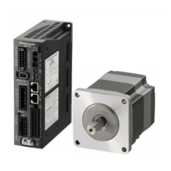
AZ Series / Motorized Actuator
equipped with AZ Series
mini Driver
EtherNet/IP™ Compatible
USER MANUAL
Thank you for purchasing an Oriental Motor product.
This Manual describes product handling procedures and safety precautions.
• Please read it thoroughly to ensure safe operation.
• Always keep the manual where it is readily available.
HM-60447
Introduction
Hardware
Implicit communication
Parameter ID lists
Troubleshooting
Reference materials
Advertisement
Table of Contents

Related Manuals for Oriental motor A Step AZ Series


Summary of Contents for Oriental motor A Step AZ Series
- Page 1 USER MANUAL Troubleshooting Reference materials Thank you for purchasing an Oriental Motor product. This Manual describes product handling procedures and safety precautions. • Please read it thoroughly to ensure safe operation. • Always keep the manual where it is readily available.
-
Page 2: Table Of Contents
Introduction Before using the product ............................6 Operating manuals ..............................7 Related operating manuals ..................................7 How to use operating manuals................................7 Overview of the product ............................. 9 Safety precautions ..............................10 Precautions for use ..............................12 Hardware System configuration ..............................16 Preparation ..................................17 Checking the product ..................................17 How to identify the product model ............................... - Page 3 Implicit communication Flow of Implicit communication ..........................38 Guidance ..................................39 Communication specifications ..........................42 Implicit message.................................43 Implicit message format ..................................43 Input data ........................................ 44 Output data ......................................47 Processing order of Implicit communication ..........................51 Data writing ......................................52 Data reading ......................................53 Example of execution for operation ........................55 Positioning operation..................................
- Page 4 JOG/HOME/ZHOME operation information setting parameters ..................84 8-10 Alarm setting parameters .................................. 85 8-11 Information setting parameters ..............................85 8-12 I/O parameters ....................................... 87 8-13 Direct I/O setting parameters ................................90 8-14 Remote I/O setting parameters ............................... 90 8-15 Virtual input parameters ..................................91 8-16 User output setting parameters ..............................
- Page 5 Introduction This part explains the product overview and safety precautions in addition to the types and descriptions about operating manuals. Table of contents Before using the product ....... 6 Operating manuals ......... 7 2-1 Related operating manuals ......7 2-2 How to use operating manuals ....7 Overview of the product ......
-
Page 6: Before Using The Product
The product described in this document has been designed and manufactured to be incorporated in general industrial equipment. Do not use for any other purpose. Oriental Motor Co., Ltd. is not responsible for any compensation for damage caused through failure to observe this warning. -
Page 7: Operating Manuals
Operating manuals Operating manuals Related operating manuals For operating manuals, download from Oriental Motor Website Download Page or contact your nearest Oriental Motor sales office. • AZ Series / Motorized Actuator equipped with AZ Series mini Driver EtherNet/IP Compatible USER MANUAL (this document) •... - Page 8 Operating manuals Installation and connection Before starting operation Setting of IP address 2 Hardware 1 Before starting operation *1 2 Hardware Setting of parameters Operation 3 Implicit communication 3 Implicit communication 4 Parameter ID lists 2 Operation 4 Parameters 3 I/O signals 7 Address/code lists 8 Measures for various cases 11 Appendix *2...
-
Page 9: Overview Of The Product
The EDS file (Electronic Data Sheets file) is a file that describes the specific information of the EtherNet/IP compatible products. Importing the EDS file to the setting tool of the scanner can perform the settings of EtherNet/IP before the driver is delivered to you. For details, contact your nearest Oriental Motor sales office. -
Page 10: Safety Precautions
Safety precautions Safety precautions The precautions described below are intended to ensure the safe and correct use of the product, and to prevent the user and other personnel from exposure to the risk of injury. Use the product only after carefully reading and fully understanding these instructions. - Page 11 Safety precautions General • Do not use the driver beyond the specifications. Doing so may result in electric shock, injury, or damage to equipment. • Keep your fingers and objects out of the openings in the driver. Failure to do so may result in fire, electrical shock, or injury.
-
Page 12: Precautions For Use
Precautions for use This chapter explains restrictions and requirements the user should consider when using the product. z Always use Oriental Motor cables to connect a motor and a driver. Refer to the cable models on p.34. z When conducting the insulation resistance measurement or the dielectric strength test, be sure to separate the connection between the motor and the driver. - Page 13 Precautions for use z How to fix the cable Fix the cable at two places near the connectors as shown in the figure or fix it with a wide clamp to take measures to prevent stress from being applied to the connectors. In the case of a exible cable, this area is a movable range.
- Page 15 Hardware This part explains names and functions of each part of the driver, installation and connection methods, and so Table of contents System configuration ......16 4-4 Connecting the USB cable ......26 4-5 Connecting input signals (CN5) ....26 Preparation ..........
-
Page 16: System Configuration
System configuration System configuration PC in which the MEXE02 Host controller has been installed EtherNet/IP Driver EtherNet/IP EtherNet/IP compatible compatible product product Control Circuit Noise lter power supply *1 AC power supply breaker *2 Circuit Noise lter Main power supply AC power supply breaker *2 Motor... -
Page 17: Preparation
This chapter explains the items you should check, as well as names and functions of each part. Checking the product Verify that the items listed below are included. Report any missing or damaged items to the Oriental Motor sales office from which you purchased the product. -
Page 18: Information About Nameplate
Preparation Information about nameplate The figure shows an example. Driver model Serial number Manufacturing date Names and functions of parts PWR/ALM LED (Green/red/blue) MS LED (Green/red) Input signal connector (CN5) NS LED (Green/red) USB connector IP address setting switch (IP ADDR ×1) L/A LED (Green) Mounting hole Cutout for mounting... -
Page 19: Indication Of Leds
Preparation Indication of LEDs „ PWR/ALM LED This LED indicates the status of the driver. LED status Description No light The main power supply and the control power supply are not turned on. Green light The main power supply and/or the control power supply are turned on. An alarm is being generated. - Page 20 Preparation „ NS LED This LED indicates the communication status of EtherNet/IP. LED status Description Green • This is in an offline state. No light No light • The main power supply and the control power supply of the driver are not turned on. Blinking No light This is in an online state.
-
Page 21: Installation
Installation Installation This chapter explains the installation location and installation method of the driver. Installation location The driver is designed and manufactured to be incorporated in equipment. Install it in a well-ventilated location that provides easy access for inspection. The location must also satisfy the following conditions: •... - Page 22 Installation „ Dimensions [Unit: mm (in.)] Mass: 0.11 kg (0.24 lb.) 69 [2.72] 4 [0.16] 61 [2.4] 30 [1.18] 2 [0.08]...
-
Page 23: Connection
*3 Motor Connect to CN1 *1 It is an Oriental motor cable. Purchase is required separately. *2 Connecting the control power supply allows you to continue monitoring even if the main power supply is shut off. Connect it as necessary. -
Page 24: Connecting The Main Power Supply And The Control Power Supply (Cn1)
Connection Connecting the main power supply and the control power supply (CN1) Connect a main power supply to the CN1 connector. Connecting the control power supply allows you to continue monitoring even if the main power supply is shut off. Connect it as necessary. - Page 25 Connection „ Internal input circuit The driver can be used with the main power supply and control power supply, or with the main power supply only. When using only the main power supply, the power is supplied from the main power supply to the control power supply circuit inside the driver.
-
Page 26: Connecting The Ethernet/Ip Cable (Cn3, Cn4)
Connection Connecting the EtherNet/IP cable (CN3, CN4) Connect the EtherNet/IP cable to the EtherNet/IP connector (CN3, CN4). „ Pin assignment Signal name Description Transmitted data + Transmitted data − Received data + N.C. N.C. N.C. − N.C. − N.C. N.C. Received data −... -
Page 27: Noise Elimination Measures
• When relays or electromagnetic switches are used, use noise filters or CR circuits to suppress surge generated by them. • Use an Oriental Motor connection cable when extending the wiring distance between the motor and the driver. Refer to p.34 for the model name. This is effective in suppressing the electrical noise emitted from the motor. -
Page 28: Conformity To Emc
The use of the following installation and wiring methods will enable the motor and driver to be compliant with EMC. Oriental Motor conducts EMC testing on its motors and drivers in accordance with “Example of installation and wiring” on p.29. The user is responsible for ensuring the machine’s compliance with EMC, based on the installation and wiring explained below. - Page 29 *1 The driver is grounded by making the heat sink contact directly with the grounded panel. *2 An Oriental Motor cable is used. • The driver uses components that are sensitive to static electricity. Take measures against static electricity since static electricity may cause the driver to malfunction or suffer damage.
-
Page 30: Setting Of Ip Address
Setting of IP address Setting of IP address The IP address, subnet mask, and default gateway are XXX. XXX. XXX. configured respectively as follows. Fourth octet Third octet Second octet First octet Setting method of IP address The following three methods can be used to set the IP address, subnet mask, and default gateway. Set item Specific setting method IP address... -
Page 31: When Setting With Parameters
Setting of IP address • When setting the switch, turn on the main power supply and the control power supply again. The new setting is enabled when the main power supply and the control power supply are turned on again. •... -
Page 32: When Setting With Dhcp Server
Setting of IP address When setting with DHCP server The IP address, subnet mask and default gateway are automatically assigned from the DHCP server. Set the IP address setting switch of the driver to “0” and the “Configuration Control” parameter to “2: DHCP server. ” The parameters and the DHCP server cannot be used in combination. -
Page 33: Inspection And Maintenance
The driver uses semiconductor components. Static electricity may damage the semiconductor components of the driver, so be extremely careful when handling them. Warranty Check on the Oriental Motor Website for the product warranty. Disposal Dispose the product correctly in accordance with laws and regulations, or instructions of local governments. -
Page 34: Cable
Cable Cable Connection cables „ Connection cables/Flexible connection cables (For AZM14, AZM15, AZM24, AZM26) These cables are used when connecting a motor and a driver. Connection cable When installing the motor on a moving part, use a flexible cable. z Connection cables z Flexible connection cables For motor/encoder For motor/encoder... - Page 35 Cable „ Connection cables/Flexible connection cables (For AZM46, AZM48, AZM66, AZM69) These cables are used when connecting a motor and a driver. The figure shows an example when the electromagnetic brake motor is used. Connection cable When installing the motor on a moving part, use a flexible cable. z Connection cables For motor/encoder For motor/encoder/electromagnetic brake...
-
Page 36: Power Supply Cable
Cable „ Extension cables/Flexible extension cables These cables are used when extending a connection cable (add between the driver and connection cable). Use if the length of the connection cable used is not enough when extending the distance between a motor and a driver. - Page 37 Implicit communication This part explains how to control via Implicit communication. Table of contents Flow of Implicit communication ..38 Guidance ..........39 Communication specifications ... 42 Implicit message ........43 4-1 Implicit message format ......43 4-2 Input data ............44 4-3 Output data ............
-
Page 38: Implicit Communication
Flow of Implicit communication Flow of Implicit communication The contents of are explained in this manual. Refer to the AZ Series OPERATING MANUAL Function Edition for the contents of is the title name described in the reference destination. Be sure to turn off the main power supply and control power supply of the driver before setting the switch. -
Page 39: Guidance
• Before operating the motor, check the condition of the surrounding area to ensure safety. • Before starting based on the guidance, import the EDS file to the setting tool of the scanner and register the system configuration in advance. For details, contact your nearest Oriental Motor sales office. - Page 40 *3 Motor Connect to CN1 *1 It is an Oriental motor cable. Purchase is required separately. *2 Connecting the control power supply allows you to continue monitoring even if the main power supply is shut off. Connect it as necessary.
- Page 41 Guidance STEP 4 The scanner starts the motor. As an example, this section explains how to perform the following positioning operation. z Setting example • Operation data number: 1 • Position: 5,000 steps • Other settings: Initial values z Operation processing flow Descriptions are given using the scanner as the subject.
-
Page 42: Communication Specifications
Communication specifications Communication specifications Communication standards EtherNet/IP (conforms to CT18) Vendor ID 187: Oriental Motor Company Device type 43: Generic Device Transmission rate 10/100 Mbps (autonegotiation) Communication mode Full duplex/Half duplex (autonegotiation) Shielded twisted pair (STP) cable Cable specifications straight-through/crossover cable, category 5e or higher is recommended Output (scanner →... -
Page 43: Implicit Message
Implicit message Implicit message Implicit message format This section shows transfer contents of implicit message. The order of data is in little-endian format. Byte Input (driver → scanner) Output (scanner → driver) 0, 1 Remote I/O (R-OUT) Remote I/O (R-IN) 2, 3 Operation data number selection_R Operation data number selection... -
Page 44: Input Data
Implicit message Input data Data transferred from a driver to a scanner is called Input data. „ Input data format Contents of the Input data are as follows. The order of data is in little-endian format. Assembly Instance Attribute Byte Size (byte) Description 0, 1... - Page 45 Implicit message z Operation data number selection_R Name Description M0_R M1_R M2_R M3_R Output in response to an input signal. M4_R M5_R M6_R M7_R 8 to 15 Reserved 0 is returned. z Fixed I/O (OUT) This is the I/O accessed via EtherNet/IP. Assignments of signals cannot be changed. Name Description SEQ-BSY...
- Page 46 Implicit message z Command position Name Description This indicates the present command position. (step) 0 to 31 Command position When the wrap function is enabled, the value on the wrap coordinates is indicated. z Torque monitor Name Description This indicates the torque presently generated as a percentage of the maximum 0 to 15 Torque monitor holding torque.
-
Page 47: Output Data
Implicit message z Assignable monitor Name Description This indicates the value of the parameter set in the “Assignable monitor 0 to 31 Assignable monitor n * address n” parameter. * n: 0 to 3 Output data Data transferred from a scanner to a driver is called Output data. „... - Page 48 Implicit message „ Details of Output data z Remote I/O (R-IN) This is the I/O accessed via EtherNet/IP. The assignments of signals can be changed using the “R-IN input function” parameters. Initial Name Description assignment R-IN0 R-IN1 R-IN2 R-IN3 R-IN4 R-IN5 R-IN6 R-IN7...
- Page 49 Implicit message z Fixed I/O (IN) This is the I/O accessed via EtherNet/IP. Assignments of signals cannot be changed. Initial Name Description value FW-JOG This is used to execute JOG operation in the forward direction. RV-JOG This is used to execute JOG operation in the reverse direction. Reserved A value is disregarded.
- Page 50 Implicit message z Direct data operation position Name Description Initial value This is used to set the target position for direct data operation. Direct data operation 0 to 31 [Setting range] position −2,147,483,648 to 2,147,483,647 steps z Direct data operation operating speed Name Description Initial value...
-
Page 51: Processing Order Of Implicit Communication
Implicit message z Write request Name Description Initial value This is used to set the write request. [Setting range] WR-REQ 0: Disable 1: Write request (ON edge) 1 to 15 Reserved A value is disregarded. z Write parameter ID Name Description Initial value 0 to 15... -
Page 52: Data Writing
Implicit message Data writing This section explains the flow that data is written from the scanner to the driver via Implicit communication. „ Area of Implicit message format used Input (transfer from driver to scanner) Output (transfer from scanner to driver) Byte Description Byte... -
Page 53: Data Reading
Implicit message Data reading This section explains the flow that data is read from the driver to the scanner via Implicit communication. There are the following two methods to read data. • Use an area of “Read data” • Use an area of “Assignable monitor” „... - Page 54 Implicit message „ When an area of assignable monitor is used z Area of Implicit message format used Input (transfer from driver to scanner) Byte Description 40 to 55 Assignable monitor 0 to assignable monitor 3 z Flow that data is read from Scanner Driver Sets the “Assignable monitor address”...
-
Page 55: Example Of Execution For Operation
Example of execution for operation Example of execution for operation This chapter describes operations that operation data is set using the write data area. The method to execute operation is common to fixed I/O and remote I/O. Positioning operation As an example, this section explains how to perform the following positioning operation. z Setting example Speed •... -
Page 56: Continuous Operation
Example of execution for operation Continuous operation As an example, this section explains how to perform the following continuous operation. z Setting example Speed • Operation data number: 0 • Rotation direction: Forward direction • Other settings: Initial values Time FW-POS z Operation processing flow Descriptions are given using the scanner as the subject. -
Page 57: Direct Data Operation
Direct data operation Direct data operation Overview of direct data operation Direct data operation is a mode that allows start of operation at the same time as rewriting of data. It is suitable to frequently change operation data such as the position (travel amount) or the operating speed, or to applications to adjust the position finely. -
Page 58: Output Data And Parameters Required For Direct Data Operation
Direct data operation „ Application example 2 of direct data operation The operating speed should be changed immediately with the touch screen because a large load is inspected at a lower speed. z Setting example • Operating speed: Change as desired •... - Page 59 Direct data operation Byte Name Description Initial value This is used to set the acceleration/deceleration rate or the acceleration/deceleration time for direct data operation. Direct data operation 16 to 19 1,000,000 [Setting range] starting/changing rate 1 to 1,000,000,000 (1=0.001 kHz/s, 1=0.001 s, or 1=0.001 ms/kHz) This is used to set the stopping deceleration rate or the stop time for direct data operation.
- Page 60 Direct data operation „ Data forwarding destination During direct data operation, the stored area when the next direct data is transferred can be selected. z When the forwarding destination is set to “0: Execution memory” If the TRIG is turned from OFF to ON or the data corresponding to the trigger is changed, the data during operation can be rewritten to the next direct data.
-
Page 61: Operation Example
Direct data operation Operation example A condition to execute direct data operation can be selected from the ON edge or ON level of TRIG of fixed I/O (IN). A condition can be selected with the TRIG-MODE of fixed I/O (IN). Before operating the motor, check the condition of the surrounding area to ensure safety. - Page 62 Direct data operation „ When direct data operation is executed at ON level of TRIG This section explains how to execute the following direct data operation with setting the trigger to “position. ” Set the trigger with the “Direct data operation trigger setting” parameter. z Setting example •...
- Page 63 Direct data operation • To execute direct data operation of the operation 2, set a different value from the operation 1 in the “position” of the operation 2. • If a value other than the “position” is changed, direct data operation of the operation 2 will not be executed.
- Page 65 Parameter ID lists This part describes the parameter ID lists to be set via EtherNet/IP. Data and parameters described here can also be set using the MEXE02 software. Table of contents Timing for parameter to update ..66 8-3 Coordinate parameters ......... 82 8-4 Operation parameters ........
-
Page 66: Timing For Parameter To Update
Timing for parameter to update Timing for parameter to update All data used with the driver is 32 bits wide. Parameters are saved in the RAM or non-volatile memory of the driver. Parameters stored in the RAM are erased once the main power supply and control power supply are shut off, however, those stored in non-volatile memory are retained even if these power supplies are shut off. -
Page 67: Maintenance Commands
Maintenance commands Maintenance commands Maintenance commands are used to execute the alarm reset, clear latch information, batch processing of the non- volatile memory and others. Refer to the AZ Series OPERATING MANUAL Function Edition for details about parameters. When checking the AZ Series OPERATING MANUAL Function Edition, use the parameter name instead of the parameter ID. -
Page 68: Monitor Commands
Monitor commands Monitor commands Monitor commands are used to monitor the command position, command speed, alarm and information history and others. All commands are used for read (READ). Refer to the AZ Series OPERATING MANUAL Function Edition for details about parameters. When checking the AZ Series OPERATING MANUAL Function Edition, use the parameter name instead of the parameter ID. - Page 69 Monitor commands Parameter ID Name 0080h Sequence history 1 0081h Sequence history 2 0082h Sequence history 3 0083h Sequence history 4 0084h Sequence history 5 0085h Sequence history 6 0086h Sequence history 7 0087h Sequence history 8 0088h Sequence history 9 0089h Sequence history 10 008Ah...
- Page 70 Monitor commands Parameter ID Name 1292 050Ch Alarm history details (Main power supply time) [min] 1296 0510h Information history 1 1297 0511h Information history 2 1298 0512h Information history 3 1299 0513h Information history 4 1300 0514h Information history 5 1301 0515h Information history 6...
- Page 71 Monitor commands Parameter ID Name 1490 05D2h Latch monitor feedback position (I/O event − High event) 1491 05D3h Latch monitor target position (I/O event − High event) 1492 05D4h Latch monitor operation number (I/O event − High event) 1493 05D5h Latch monitor number of loop (I/O event −...
- Page 72 Monitor commands „ I/O status The arrangement of bits for internal I/O is indicated. z Input signals Parameter ID Description Bit 31 Bit 30 Bit 29 Bit 28 Bit 27 Bit 26 Bit 25 Bit 24 SLIT HOMES RV-LS FW-LS RV-BLK FW-BLK −...
- Page 73 Monitor commands z Output signals Parameter ID Description Bit 31 Bit 30 Bit 29 Bit 28 Bit 27 Bit 26 Bit 25 Bit 24 MAREA − RND-ZERO RV-SLS FW-SLS RND-OVF Bit 23 Bit 22 Bit 21 Bit 20 Bit 19 Bit 18 Bit 17 Bit 16...
-
Page 74: Operation Data R/W Commands
Operation data R/W commands Operation data R/W commands This is a method in which the parameter ID (base address) of the base operation data number is specified to Input data. Refer to “4-3 Setting example” on p.77 for how to use the base address. Base address of each operation data number Base address Base address... - Page 75 Operation data R/W commands Base address Base address Base address Base address Operation Operation Operation Operation data data data data 7936 1F00h No.152 8768 2240h No.178 9600 2580h No.204 10432 28C0h No.230 7968 1F20h No.153 8800 2260h No.179 9632 25A0h No.205 10464 28E0h...
-
Page 76: Parameter Id
Operation data R/W commands Parameter ID The setting item of operation data is set with the operation data R/W command. The parameter ID for the setting item is arranged based on the base address of the operation data number. (Base address p.74) For example, in the case of the setting item "Position,"... -
Page 77: Setting Example
Operation data R/W commands Parameter ID Name Setting range Initial value Update −1: None (−) (High) I/O event Base address +15 0 to 31: Operation I/O event number −1 number (0 to 31) Setting example As an example, this section explains how to set the following operation data to the operation data No.0 to No.2. Setting item Operation data No.0 Operation data No.1... -
Page 78: Operation I/O Event R/W Commands
Operation I/O event R/W commands Operation I/O event R/W commands If a specified event (ON/OFF of I/O) is generated during operation of the motor, another operation can be started. This is called operation I/O event. This chapter explains the address to execute the operation I/O event. Base address of operation I/O event Base address Base address... -
Page 79: Protect Release Commands
Protect release commands Protect release commands The key codes for reading/writing of data from/to the backup area and the key codes for release of function limitation by the HMI input are set. Refer to the AZ Series OPERATING MANUAL Function Edition for details about parameters. When checking the AZ Series OPERATING MANUAL Function Edition, use the parameter name instead of the parameter ID. -
Page 80: Extended Operation Data Setting R/W Command
Extended operation data setting R/W command Extended operation data setting R/W command Parameters for extended operation data setting can be set. Refer to the AZ Series OPERATING MANUAL Function Edition for details about parameters. When checking the AZ Series OPERATING MANUAL Function Edition, use the parameter name instead of the parameter ID. Parameter ID Name Setting range... -
Page 81: Parameter R/W Commands
Parameter R/W commands Parameter R/W commands These commands are used to write or read parameters. Refer to the AZ Series OPERATING MANUAL Function Edition for details about parameters. When checking the AZ Series OPERATING MANUAL Function Edition, use the parameter name instead of the parameter ID. Driver action simulation setting parameter Parameter ID Initial... -
Page 82: Coordinate Parameters
Parameter R/W commands * It is used to set the voltage mode of the main power supply. The voltage mode of the main power supply is discriminated in 50 ms after the main power supply is turned on. Set the “Main power mode” parameter to "0: 24 VDC"... -
Page 83: Abzo Sensor Setting Parameters
Parameter R/W commands ABZO sensor setting parameters Parameter ID Initial Name Setting range Update value 0: Prioritize ABZO setting 2032 07F0h Mechanism settings 1: Manual setting Initial coordinate generation & wrap 0: Prioritize ABZO setting 2034 07F2h coordinate setting 1: Manual setting 0: Follow ABZO setting 2035 07F3h... -
Page 84: Jog/Home/Zhome Operation Information Setting Parameters
Parameter R/W commands z Value that can be set in the "Initial coordinate generation & wrap setting range" parameter Since the internal coordinate of the ABZO sensor is 1,800 rev (or 900 rev), select a value from the table, and set in the “Initial coordinate generation &... -
Page 85: Alarm Setting Parameters
Parameter R/W commands Parameter ID Name Setting range Initial value Update (HOME) Backward steps in 2 sensor 0169h 0 to 8,388,607 steps home-seeking (HOME) Operating amount in uni- 016Ah 0 to 8,388,607 steps directional home-seeking (HOME) Operating current for push- 016Bh 0 to 1,000 (1=0.1 %) 1,000... - Page 86 Parameter R/W commands Parameter ID Name Setting range Initial value Update 0: Disable 01B3h Cumulative load value auto clear 1: Enable 01B4h Cumulative load value count divisor 1 to 32,767 128: 01BCh INFO-USRIO output selection Output signals list p.95 CONST-OFF 0: Not invert 01BDh INFO-USRIO output inversion...
-
Page 87: I/O Parameters
Parameter R/W commands Parameter ID Name Setting range Initial value Update INFO action (I/O test mode information 0: No info reflect 1981 07BDh (INFO-IOTEST)) (Only the bit output is ON.) INFO action (Configuration request 1: Info reflect 1982 07BEh information (INFO-CFG)) (The bit output and the INFO output are ON and the LED INFO action (Reboot request... - Page 88 Parameter R/W commands Parameter ID Initial Name Setting range Update value 0: Feedback speed attainment (speed at feedback position) 1: Speed at command position 1816 0718h VA mode selection (only internal profile) 2: Speed at feedback position & command position (only internal profile) 1817 0719h VA detection speed range...
- Page 89 Parameter R/W commands Parameter ID Initial Name Setting range Update value 1880 0758h AREA0 positioning standard 1881 0759h AREA1 positioning standard 1882 075Ah AREA2 positioning standard 1883 075Bh AREA3 positioning standard 0: Based on feedback position 1: Based on command position 1884 075Ch AREA4 positioning standard...
-
Page 90: Direct I/O Setting Parameters
Parameter R/W commands 8-13 Direct I/O setting parameters Parameter ID Name Setting range Initial value Update 2112 0840h DIN0 input function 5: STOP Input signals list p.94 2113 0841h DIN1 input function 1: FREE 2128 0850h DIN0 inverting mode 0: Not invert 1: Invert 2129 0851h... -
Page 91: Virtual Input Parameters
Parameter R/W commands Parameter ID Name Setting range Initial value Update 2333 091Dh R-OUT13 output function 134: MOVE 2334 091Eh R-OUT14 output function Output signals list p.95 138: IN-POS 2335 091Fh R-OUT15 output function 140: TLC 2352 0930h R-OUT0 OFF delay time 2353 0931h R-OUT1 OFF delay time... -
Page 92: User Output Setting Parameters
Parameter R/W commands 8-16 User output setting parameters Parameter ID Name Setting range Initial value Update 2400 0960h User output (USR-OUT0) source A function Output signals list 128: CONST-OFF p.95 2401 0961h User output (USR-OUT1) source A function 2402 0962h User output (USR-OUT0) source A inverting mode 0: Not invert 1: Invert... - Page 93 Parameter R/W commands z IP address setting parameters These are set using the MEXE02 software. They cannot be read or written via Implicit communication. Parameter ID Name Description Setting range Initial value Update Sets how to obtain the IP 0: Parameter −...
-
Page 94: I/O Signals Assignment List
I/O signals assignment list I/O signals assignment list To assign signals via industrial network, use the "assignment numbers" in the table instead of the signal names. Input signals Assignment Assignment Assignment Signal name Signal name Signal name number number number Not used SSTART RV-PSH... -
Page 95: Output Signals
I/O signals assignment list Output signals Assignment Assignment Assignment Signal name Signal name Signal name number number number Not used FW-POS_R ABSPEN FREE_R RV-POS_R ELPRST-MON C-ON_R FW-SPD_R PRST-DIS CLR_R RV-SPD_R PRST-STLD STOP-COFF_R FW-PSH_R ORGN-STLD STOP_R RV-PSH_R RND-OVF PAUSE_R M0_R FW-SLS BREAK-ATSQ_R M1_R RV-SLS... - Page 96 I/O signals assignment list Assignment Assignment Signal name Signal name number number D-END1 INFO-START D-END2 INFO-ZHOME D-END3 INFO-PR-REQ D-END4 INFO-EGR-E D-END5 INFO-RND-E D-END6 INFO-FW-OT D-END7 INFO-RV-OT INFO-USRIO INFO-CULD0 INFO-POSERR INFO-CULD1 INFO-DRVTMP INFO-TRIP INFO-MTRTMP INFO-ODO INFO-OVOLT INFO-DSLMTD INFO-UVOLT INFO-IOTEST INFO-OLTIME INFO-CFG INFO-SPD INFO-RBT...
- Page 97 Troubleshooting This part explains alarm and information functions. Table of contents Detection of communication errors .. 98 1-1 Communication timeout ......98 1-2 IP address conflict ........... 98 Alarms ............99 2-1 Alarm reset ............99 2-2 Alarm history ............ 99 2-3 Generation condition of alarms ....
-
Page 98: Detection Of Communication Errors
Detection of communication errors Detection of communication errors This chapter explains a function to detect that an error occurred in EtherNet/IP. Communication timeout If Implicit communication is interrupted due to disconnection of the EtherNet/IP cable or other reasons, the communication timeout is detected. When the communication timeout is detected, the NS LED on the driver blinks in red. -
Page 99: Alarms
Alarms Alarms This driver has the alarm function to protect from temperature rise, poor connection, error in operation, and the like. If an alarm is generated, the ALM-A output is turned ON and the ALM-B output is turned OFF to stop the motor. At the same time, the PWR/ALM LED blinks in red. -
Page 100: Alarm List
Contact your nearest Oriental Motor sales office. The internal temperature of the Main circuit Reconsider the ventilation Any of reset Non-... - Page 101 If the alarm has still not reset, the driver may be damaged. Contact your nearest Oriental Motor sales office. Turn off the main power supply Turn on the and the control power supply, and...
- Page 102 Execute either of the following operations. If the same alarm is still generated, the ABZO sensor has been damaged. Contact your Turn on the nearest Oriental Motor sales main power Encoder EEPROM The data stored in the ABZO Non- office.
- Page 103 Alarms Number of Alarm Motor times LED Alarm type Cause Remedial action How to reset code excitation * blinks • Reconsider the connection status of the load and the position of the HOME sensor so that these signals should be ON None of the TIM output, the while the HOMES input is ON.
- Page 104 Alarms Number of Alarm Motor times LED Alarm type Cause Remedial action How to reset code excitation * blinks Implicit communication of Check the connection with the Exclusive Owner connection Any of reset Network bus error scanner and the condition of the Excitation was disconnected during operations...
-
Page 105: Timing Chart
Alarms Timing chart „ When the motor remains in an excitation state even if an alarm is generated 1. If an error occurs, the ALM-B output and the MOVE output are turned OFF. At the same time, the motor stops instantaneously. 2. - Page 106 Alarms „ When the motor puts into a non-excitation state if an alarm is generated 1. If an error occurs, the ALM-B output and the MOVE output are turned OFF. At the same time, the motor stops instantaneously. 2. When resetting the alarm, turn the operation command OFF, If the alarm is reset while the operation command is input, the motor may start suddenly, causing injury or damage to equipment.
-
Page 107: Information
Information Information The driver is equipped with a function to generate information output before an alarm is generated. This function can be utilized for periodic maintenance of equipment by setting a suitable value in the parameter of each information. For example, utilizing the “Motor temperature information” parameter can prevent equipment malfunction or production stoppage due to motor overheat. - Page 108 Information Parameter ID Parameter name Description Initial value Sets the condition in which the undervoltage information (INFO-UVOLT) is generated. Undervoltage information (INFO- 01ACh UVOLT) [Setting range] 140 to 630 (1=0.1 V) Sets the condition in which the tripmeter information (INFO-TRIP) is generated. 01AFh Tripmeter information (INFO-TRIP) [Setting range]...
- Page 109 Information Parameter ID Parameter name Description Initial value INFO action (Assigned I/O status 1952 07A0h information (INFO-USRIO)) INFO action (Position deviation 1953 07A1h information (INFO-POSERR)) INFO action (Driver temperature 1954 07A2h information (INFO-DRVTMP)) INFO action (Motor temperature 1955 07A3h information (INFO-MTRTMP)) INFO action (Overvoltage 1956 07A4h...
-
Page 110: Information History
Information Information history Up to 16 generated information items are stored in the RAM in order of the latest to the oldest. Information items stored as the information history are the information code, generation time, and contents of information. The information history stored in the RAM can be read or cleared if one of the following is performed. •... - Page 111 Information Information bit output Information item Cause Reset condition signal • The operation start signal in the direction having been stopped by the FW-BLK input or RV-BLK input was turned ON. • The operation start signal in the direction having been stopped by the FW-LS input or RV-LS input was turned ON.
- Page 112 Information Information bit output Information item Cause Reset condition signal After the following operation was performed, the cumulative travel distance (Odometer) of the motor The cumulative travel distance of the motor fell below the value set in the Odometer INFO-ODO exceeded the value set in the "Odometer "Odometer information”...
-
Page 113: Troubleshooting And Remedial Actions
In motor operation, the motor or the driver may not operate properly due to an improper setting or wrong connection. When the motor operation cannot be performed properly, refer to the contents provided in this chapter and take an appropriate remedial action. If the problem persists, contact your nearest Oriental Motor sales office. Phenomenon Possible cause Remedial action Connection error of the motor •... - Page 114 Troubleshooting and remedial actions Phenomenon Possible cause Remedial action Lower the current with the "Base current" parameter. If The load is small. the motor output torque is too large with respect to a load, vibration will increase. The “Main power mode” parameter Check the setting of the "Main power mode"...
- Page 115 Reference materials Table of contents Timing chart .........116 Specifications ........118 2-1 Product specifications .........118 2-2 General specifications .........118 Regulations and standards ....119...
-
Page 116: Timing Chart
Timing chart Timing chart „ Power activation z When a control power supply is used 10 s or more Control power supply 2 s or less 1 s or less SYS-RDY (ready to read output, Ready ready to accept input) Not ready 4 s or less 1 s or less... - Page 117 Timing chart z When a control power supply is not used 10 s or more Main power supply 2 s or less 1 s or less SYS-RDY (ready to read output, Ready ready to accept input) Not ready 4 s or less 1 s or less EtherNet/IP communication Completed...
-
Page 118: Specifications
Specifications Specifications Product specifications 24 VDC±5 % Rated voltage 48 VDC±5 % Main power Input current 0.4 to 3.7 A *1 supply Allowable operating 24 VDC input: 20 to 32 VDC (22.8 to 32 VDC) *2 voltage 48 VDC input: 40 to 55 VDC 24 VDC±5 % Rated voltage 48 VDC±5 %... -
Page 119: Regulations And Standards
Regulations and standards Regulations and standards „ UL Standards, CSA Standards This product is recognized by UL under the UL and CSA Standards. Check the“ APPENDIX UL Standards for AZ Series” for recognition information about UL Standards. „ CE Marking / UKCA Marking This product is affixed with the marks under the following directives/regulations. - Page 120 If a new copy is required to replace an original manual that has been damaged or lost, please contact your nearest Oriental Motor sales office. • Oriental Motor shall not be liable whatsoever for any problems relating to industrial property rights arising from use of any information, circuit, equipment or device provided or referenced in this manual.
Need help?
Do you have a question about the A Step AZ Series and is the answer not in the manual?
Questions and answers