Table of Contents
Advertisement
Quick Links
Advertisement
Table of Contents

Related Manuals for Makita DLS713NZ


Summary of Contents for Makita DLS713NZ
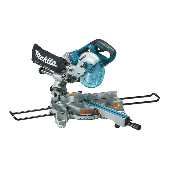
- Page 1 Questo manuale d’istruzione è fornito da trovaprezzi.it. Scopri tutte le offerte per Makita DLS713 DLS713NZ o cerca il tuo prodotto tra le migliori offerte di Elettroutensili INSTRUCTION MANUAL Cordless Slide Compound Miter Saw DLS713 011234 IMPORTANT: Read Before Using.
-
Page 2: Specifications
ENGLISH (Original instructions) SPECIFICATIONS Model DLS713 Blade diameter 190 mm Hole (arbor) diameter 20 mm Max. Miter angle Left 47° , Right 57° Max. Bevel angle Left 45°, Right 5° Max. Cutting capacities (H x W) with blade 190 mm in diameter. Bevel angle Miter angle 45°... -
Page 3: General Power Tool Safety Warnings
GEA006-2 medication. A moment of inattention while operating power tools may result in serious General Power Tool Safety personal injury. Warnings Use personal protective equipment. Always wear eye protection. Protective equipment such WARNING Read all safety warnings and all as dust mask, non-skid safety shoes, hard hat, or instructions. - Page 4 22. Keep cutting tools sharp and clean. Properly Wear hearing protection to reduce the risk of maintained cutting tools with sharp cutting edges hearing loss. are less likely to bind and are easier to control. Wear gloves for handling saw blade (saw 23.
- Page 5 29. Be careful not to damage the arbor, flanges WARNING: (especially the installing surface) or bolt. Damage to DO NOT let comfort or familiarity with product these parts could result in blade breakage. (gained from repeated use) replace strict adherence 30.
-
Page 6: Installation
Charge battery cartridge with room FUNCTIONAL DESCRIPTION temperature at 10 ゚ C - 40 ゚ C (50 ゚ F - 104 ゚ F). Let a hot battery cartridge cool down before charging it. Charge the battery cartridge once in every six WARNING: months if you do not use it for a long period of Always be sure that the tool is switched off and... -
Page 7: Blade Guard
The tool will automatically stop during operation if the tool For European countries and/or battery are placed under one of the following 1. Blade guard A conditions: 2. Blade guard B Overloaded: • The tool is operated in a manner that causes it to draw an abnormally high current. - Page 8 Do not remove spring holding blade guard. If 2. Guide fence guard becomes damaged through age or UV light 3. Turn base exposure, contact a Makita service center for a new guard. DO NOT DEFEAT OR REMOVE GUARD. Positioning kerf board 1. Thumb screw 2.
- Page 9 Stopper arm 1. Pointer 2. Bevel scale 1. Adjusting screw 3. Arm 2. Stopper arm 011301 To adjust the bevel angle, loosen the lever at the rear of 011241 the tool counterclockwise. The lower limit position of the blade can be easily Push the handle to the left to tilt the saw blade until the adjusted with the stopper arm.
- Page 10 • in unintentional operation and serious personal tool, always check to see that the switch trigger injury. Return tool to a Makita service center for actuates properly and returns to the "OFF" proper repairs BEFORE further usage. position when released. Do not pull the switch...
- Page 11 CAUTION: blade mounting part on the other side. Choose a correct Use only the Makita hex wrench provided to install • side on which blade mounting part fits into the saw blade or remove the blade.
-
Page 12: Securing Workpiece
Return the blade guard and center cover to its original 1. Support position. Then tighten the hex socket bolt clockwise to 2. Turn base secure the center cover. Release the handle from the raised position by pulling the stopper pin. Lower the handle to make sure that the blade guard moves properly. -
Page 13: Operation
Horizontal vise (optional accessory) 1. Holder assembly 1. Vise knob 2. Rod 12 2. Projection 3. Vise shaft 4. Base 002246 WARNING: 011305 The horizontal vise can be installed on the left side of the Always support a long workpiece so it is level •... - Page 14 Workpieces up to 52 mm high and 97 mm wide can Never attempt to perform a slide cut by pulling the • be cut in the following manner. carriage towards you. Pulling the carriage towards you Push the carriage toward the guide fence fully and while cutting may cause unexpected kickback resulting in tighten two clamp screws which secure the slide possible serious personal injury.
-
Page 15: Compound Cutting
come to rest against the blade. If the blade is raised 1. Inside corner while it is rotating the cut-off piece maybe ejected by the 2. Outside corner blade causing the material to fragment which may result in serious personal injury. NOTICE: When pressing down the handle, apply pressure in •... - Page 16 Lay crown molding with its broad back • (hidden) surface down on the turn base Over 15mm (5/8") Over 420mm (16-1/2") with its CEILING CONTACT EDGE against the guide fence on the saw. 50mm-60mm The finished piece to be used will (2"-2-3/8") •...
-
Page 17: Carrying Tool
Make sure that the battery cartridge is removed. Secure Groove cutting the blade at 0° bevel angle and the turn base at the full right miter angle position. Secure the slide poles so that 1. Cut grooves with the lower slide pole is locked in the position of the carriage blade fully pulled to operator and the upper poles are locked in the position of the carriage fully pushed forward to the... - Page 18 1. Lever 1. Guide fence 2. Arm holder 2. Hex socket bolt 3. 0 ゚ degree bevel angle adjusting bolt 4. Arm 5. Release button 012589 012585 Loosen the lever at the rear of the tool. Loosen the hex socket bolt securing the guide fence Turn the 0°...
-
Page 19: Replacing Carbon Brushes
Misuse of an accessory or Replacing carbon brushes attachment may result in serious personal injury. If you need any assistance for more details regarding 1. Limit mark these accessories, ask your local Makita Service Center. Carbide-tipped saw blades • Vise assembly (Horizontal vise) •... - Page 20 Makita Corporation www.makita.com 885295A4...