Table of Contents
Advertisement
Quick Links
Advertisement
Table of Contents

Related Manuals for Canon VarioPrint MICR i Series


Summary of Contents for Canon VarioPrint MICR i Series
- Page 1 VarioPrint i-series MICR Operation guide © 2015 - 2019 Canon Production Printing...
- Page 2 No part of this publication may be copied, modified, reproduced or transmitted in any form or by any means, electronic, manual or otherwise, without the prior written permission of Canon Production Printing. Illustrations and printer output images are simulated and do not necessarily apply to products and services offered in each local market.
-
Page 3: Table Of Contents
Contents Contents Chapter 1 Introduction.........................9 About the VarioPrint i-series MICR....................... 10 Information in this operation guide......................12 Users of the printer............................14 Notes for the reader............................15 Chapter 2 Safety and Environment Information................17 Chapter 3 Explore the printer......................25 Main hardware parts............................26 Paper Input ..............................29 Print Process.............................. - Page 4 Contents Define default job processing......................... 90 Download account log files........................92 Define the handling of media attributes in JDF ticket................94 Chapter 6 Job media handling......................97 Media in a central role........................... 98 Assign media from media catalog to paper trays..................99 Load media via the schedule........................101 Unpack the media............................102 Load media into the paper module......................104...
- Page 5 Contents Delete print jobs............................. 199 Duplicate a job............................200 Create a variable data job........................201 Create a note for the operator.......................203 Make changes to the job..........................205 Explore the realistic preview.........................205 Explore the pixel-precise preview......................208 Explore the layout functions......................... 215 Edit a job..............................219 Change job name, number of sets or print range.................219 Change use of special pages in job properties................
- Page 6 Contents Define color mapping...........................348 Spot color management..........................353 Learn about spot colors.........................353 Create a spot color on the control panel....................355 Create and edit a spot color in Settings Editor..................362 Read the spot color patch chart......................366 Define a spot color library........................368 Create a trapping preset..........................
- Page 7 Contents Clean the SZ-rollers in the paper path module................464 Clean the SZ-rollers in the registration input module..............467 Clean the SZ-rollers in the print module..................470 Clean the SZ-rollers in the registration output module with system tray........473 Clean the SZ-rollers in the registration output module without system tray......476 Clean the SZ-rollers in the high capacity stacker................479 Clean print belt............................
- Page 8 Contents VarioPrint i-series MICR...
-
Page 9: Chapter 1 Introduction
Chapter 1 Introduction... -
Page 10: About The Varioprint I-Series Micr
About the VarioPrint i-series MICR About the VarioPrint i-series MICR The VarioPrint i-series MICR are sheet-fed inkjet color production printers printing at 300 ipm or 200 ipm. The printer platform combines new reliable applications with proven inkjet productivity, and premium quality output. The VarioPrint i-series MICR steered by PRISMAsync Print Server offers digital workflows—black and white, highlight color, and full color—into one effective and productive platform. - Page 11 • The controller PRISMAsync Print Server ensures you to get the most out of your printer. PRISMAsync Print Server is used for a wide range of Canon color and black and white sheet- fed printers.
-
Page 12: Information In This Operation Guide
Information in this operation guide Information in this operation guide Content This operation guide helps you to achieve your business purposes while you prepare and print jobs with the VarioPrint i-series MICR. Read this operation guide to learn what the VarioPrint i-series MICR can do for you: how to operate, maintain, evaluate, and configure the printer and how to use it in a safe way. - Page 13 Increased simplex speed Other product information The following other guides are available for the VarioPrint i-series MICR. You find these guides on the downloads site http://downloads.cpp.canon. • PRISMAprofiler User guide • PRISMAlytics Dashboard Quick Reference Guide • PRISMAsync Remote Control Quick Reference Guide •...
-
Page 14: Users Of The Printer
Users of the printer Users of the printer Target group with respect to safety information A user of the printer is with respect to safety an "ordinary person." The roles of the ordinary person with respect to the printer can be different. The roles of the target group are described below. -
Page 15: Notes For The Reader
Names of options to be used in a fixed order Safety symbols Before you use this product, make sure you read and understand the safety information that "http://downloads.cpp.canon" belongs to the product. Find the safety information on . Also be sure to follow all warnings and instructions marked on the product. - Page 16 Notes for the reader Symbol Type of symbol Indicates CAUTION Laser beam Indicates a caution concerning operations that may lead to in- jury to persons if not performed correctly. To use the ma- chine safely, always pay attention to these cautions. IMPORTANT Indicates an operational requirement or restriction.
-
Page 17: Safety And Environment Information
Chapter 2 Safety and Environment Information... - Page 18 The websites of the regional Canon sales offices are listed on the cover of the User Documentation. There you can find the addresses of the local Canon sales offices.
- Page 19 CE Declaration of Conformity is part of the User Documentation. You may also "http://downloads.cpp.canon/" download it from the support site of your product at Canon Production Printing shall not be liable for damages from: • Failure to comply with the User Documentation; • Work performed incorrectly on the machine;...
- Page 20 This User Documentation describes safeguards for the protection of an ordinary person. Ordinary person is the term applied to all persons other than skilled persons. Ordinary persons include not only users of the equipment, but also all persons who may have access to the equipment or who may be in the vicinity of the equipment.
- Page 21 Power plug WARNING • If the machine is connected via a wall socket, place the machine close to a wall socket that is easily accessible. The power plug serves as a disconnecting device. • If the machine is connected via a fixed connection to the electricity grid, the power supply systems must be easily accessible.
- Page 22 Installation WARNING • The machine may only be transported, assembled, installed and repaired by an authorized service representative. • The installation of accessories and options not permitted for the machines may constitute a violation of the Safety Regulations and Directives, and may also damage the machine. •...
- Page 23 Disassemble and modification WARNING • Do not remove covers and panels that are fixed to the machine. Some machines have an electrical component or a laser beam source inside that could cause an electrical shock or injuries. • Do not modify the machine, because this can cause a fire, an electrical shock, a malfunction or injuries.
- Page 24 Disposal of parts WARNING • All parts are produced according to the sustainability policy of Canon. You can discard all used parts into a common dustbin, or follow your local or national sustainability and waste disposal procedures.
-
Page 25: Chapter 3 Explore The Printer
Chapter 3 Explore the printer... -
Page 26: Main Hardware Parts
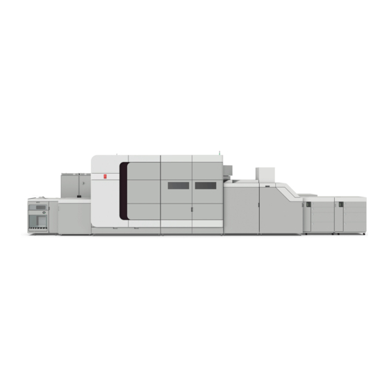
Main hardware parts Main hardware parts The VarioPrint i-series MICR is a modular printer. The modules in the front position are mainly used for the job production. The modules in the rear position give access to the consumables, service units, and control units. The VarioPrint i-series MICR can have up to three paper input modules and one or two high capacity stackers. - Page 27 Main hardware parts Description of main hardware parts The print module holds the ink printheads and the print belt. The print belt in the print module uses the suction air technique to ensure that sheets re- main flat under the printheads. Sheet cooling decreases the temperature of sheets printed on one side.
- Page 28 Main hardware parts Description of main hardware parts The fixation module with the fixation drum dries the prints with heated air. The power module is responsible for the power management. Chapter 3 - Explore the printer VarioPrint i-series MICR...
-
Page 29: Paper Input
Paper Input Paper Input The VarioPrint i-series MICR can handle a wide range of media sizes and media weights, for coated and uncoated media. The very accurate print process and the small gap between a sheet and the printheads require that sheets are in optimal shape and correctly positioned on the paper path. - Page 30 Paper Input Description paper path For duplex prints, the prints go for a second pass through the input registration unit and the print module. The paper path module interweaves sheets that were printed on one side with blank sheets. The sentry examines all sheets. The registration input module positions the sheets precisely on the paper path before they enter the print module.
- Page 31 Paper Input [6] Open (1) a paper tray and unassign (2) its media Chapter 3 - Explore the printer VarioPrint i-series MICR...
-
Page 32: Print Process
Print Process Print Process The VarioPrint i-series MICR has a drop-on-demand piezoelectric ink technology. In the print module the print belt transfers the sheets under the printheads. The nozzles of the printheads eject the ink drops. The drum of the fixation module dries the printed sheets. The printer cleans the printheads on a regular base. - Page 33 Print Process Description The sheets move in a single-pass way under the ink printheads where the nozzles eject the ink. When the printer has the MICR option, there is an extra set of printheads. The heated, fanned air dries the prints in the fixation drum. Thanks to the air separation technique the prints move from the print belt to the paper path in the fixation module.
- Page 34 Print Process [11] Nozzle receives an electric signal (A) and ejects an ink drop (B) Drop size modulation The VarioPrint i-series MICR printhead nozzles can produce drops of five different sizes. This mechanism is called drop size modulation. The largest drop size is only used to compensate for a failure of an adjacent nozzle.
-
Page 35: Paper Output
Paper output Paper output The VarioPrint i-series MICR collects the prints in one or two high capacity stackers. When additional finishing takes place, the prints are transported via the high capacity stacker to the third-party finisher. Location of the paper output process There are two models of the registration output module. - Page 36 Paper output Transport of the prints during the paper output process [16] Transport of prints during the paper output process (model without system tray) [17] Transport of prints during the paper output process (model with system tray) Description paper path The registration output module receives the prints.
- Page 37 Paper output [18] High capacity stacker Description The front door gives access to the registration unit and the paper path. The front cover gives access to the flip rings and the paper path. The slide door protects the stacks. The top cover gives access to the paper path. The control panel shows the filling level and has a button to eject the stack manually.
- Page 38 Paper output Description control panel The full tray indicator indicates the status of the stack tray. [20] 1. Stack is ejected soon. 2. Stack is ejected. The stack height indicator indicates the filling level of the stack tray. [21] 1. Stack tray is filled. 2. Stack tray is full. The eject button enables a manual stack eject.
-
Page 39: Print Quality Aspects
Print quality aspects Print quality aspects The VarioPrint i-series MICR offers flexibility to make the optimal media choices for your applications and print business. In practice, the job workflow of the VarioPrint i-series MICR is based around the use of the media catalog. -
Page 40: Optional Finishers And Other Devices
Optional finishers and other devices Optional finishers and other devices Dual paper tray Introduction The dual paper tray enables you to load 2 stacks of the same media in one paper tray. When the first stack of media becomes empty, the printing stops. The second stack is moved to the left- hand side and printing continues. - Page 41 Dual paper tray Icon Description The left-hand stack of the dual paper tray is partly filled. NOTE Each line of the left-hand stack indicates the presence of about 100 sheets. The right-hand stack of the dual paper tray is partially or completely fil- led.
-
Page 42: Paper Module Flex Xl
Paper module Flex XL Paper module Flex XL The paper module Flex XL is the same as the standard paper module. The only difference is that the two large paper trays are replaced by Flex XL trays. A Flex XL tray can contain media until media size 350 mm x 508 mm. -
Page 43: Integrated Camera Mounting Unit Icmu
Integrated camera mounting unit ICMU Integrated camera mounting unit ICMU The integrated camera mounting unit ICMU is a unit that can contain a camera system. With the camera system you can compare the actual printed sheets with the digital original. When the printed image and the original do not match the print job is aborted. - Page 44 Integrated camera mounting unit ICMU Chapter 3 - Explore the printer VarioPrint i-series MICR...
-
Page 45: Chapter 4 Getting Started
Chapter 4 Getting started... -
Page 46: Interfaces To Access The Printer
Interfaces to access the printer Interfaces to access the printer There are several starting points to use the VarioPrint i-series MICR. Whether you access the printer via the control panel or remotely via PRISMAsync Remote Manager, you quickly find your way while operating the VarioPrint i-series MICR. - Page 47 Interfaces to access the printer [24] Control panel The table below describes the main parts of the control panel and their functions. Description The sleep button brings the printer into the sleep mode or awakes the printer from the sleep mode. The stop button stops the print process, after a set, after a record, or as soon as possible.
- Page 48 Interfaces to access the printer [25] Remote printer driver The table below describes the main parts of the printer driver and their functions. Use the online help of the printer driver when you need more information. Parts Description Printer configuration Finishing options of the printer.
- Page 49 Interfaces to access the printer Parts Description Job template The template bundles the current job properties. Save a tem- plate to use later for other jobs. Submit job The job is submitted when you click the OK button. PRISMAsync Remote Manager PRISMAsync Remote Manager is a multi-printer schedule and remote management console to control PRISMAsync Print Server-driven printers.
- Page 50 Interfaces to access the printer Description The lists of scheduled jobs on the selected printer. The toolbars have buttons to move, add, edit, and print jobs. The lists of waiting jobs on the selected printer. The DocBox and list of printed jobs. PRISMAsync Remote Control The PRISMAsync Remote Control app helps the central operator to stay informed about the print production on the available PRISMAsync Print Server printers.
- Page 51 Interfaces to access the printer [29] Settings Editor Description The settings are grouped in main and sub tabs. Use the search box to quickly find a setting. Use the link to start PRISMAsync Remote Manager. Click the user name to log in to the Settings Editor, log out or change the password. A red exclamation mark indicates that a default password is used.
-
Page 52: Log In, Log Out, And Change Passwords
Log in, log out, and change passwords Log in, log out, and change passwords Log in to the printer This topic contains the following instructions. 1. Access the printer without login 2. Log in with a domain user account 3. Log in with a factory defined user account 4. - Page 53 Log in to the printer [31] Log in with domain user account 1. Select the domain from the [Domain] drop-down list. 2. Enter your username and password. 3. Touch or click [OK]. Log in with a factory defined user account When you use a factory defined user account, you can select the user account from a list.
- Page 54 Log in to the printer Log in with a custom user account When you use a custom user account, you need to log in with a username. [34] Log in with custom user account 1. When the [Domain] drop-down list is displayed, select the hostname or IP address of the printer.
- Page 55 Log in to the printer [37] Password Chapter 4 - Getting started VarioPrint i-series MICR...
-
Page 56: Log Out Or Switch Roles
Log out or switch roles Log out or switch roles This topic contains the following instructions. 1. End the session 2. Log out on the control panel and the Settings Editor 3. Log out on control panel when you use a PKI smart card 4. - Page 57 Log out or switch roles Switch roles to change settings When you are logged in to the Settings Editor or to the control panel and you want to perform a task for which you do not have sufficient rights, you can log in again with the appropriate credentials.
-
Page 58: Change Password
Change password Change password When do you need to change your password You are strongly recommended to follow the security guidelines of your organization. The definition of your password is part of these security guidelines. You are warned when your password no longer meets the guidelines. - Page 59 Change password [44] Change password 4. Enter your new password and confirm the new password. NOTE It depends on the security guidelines of your organization if you can reuse a previously used password. 5. Touch or click [OK]. Chapter 4 - Getting started VarioPrint i-series MICR...
-
Page 60: Recover Password
Recover password Recover password This topic contains the following instructions. 1. Recover password from control panel 2. Recover password from Settings Editor or PRISMAsync Remote Manager What is a password recovery mail If you have lost your password, you can define a new password via a password recovery email. The email that holds the link to define a new password, is sent to the email address that belongs to your user account. - Page 61 Recover password [46] Recover password 4. Touch [Forgot password?]. Recover password from Settings Editor or PRISMAsync Remote Manager 1. Click [Recover password] at the login window. [47] Recover password 2. Click [OK]. Chapter 4 - Getting started VarioPrint i-series MICR...
-
Page 62: Learn About The Printer Status
Learn about the printer status Learn about the printer status Power states of theVarioPrint i-series MICR The VarioPrint i-series MICR has four power states. • Active: The printer is printing jobs, processing jobs or performing maintenance tasks. • Ready: The printer is ready to accept user comments or to accept print jobs. •... - Page 63 Learn about the printer status [49] The status bar on the dashboard (1), the control panel (2) and the operator attention light (3) Color Action required Green informs that there is no upcoming event. Orange warns that there is an upcoming event, such as loading paper trays or re- moving prints from the output trays.
- Page 64 Learn about the printer status [50] Schedule Required maintenance The dashboard shows messages and symbols when a maintenance action is expected soon or must be done immediately. When the printer cannot continue printing because supplies need to be refilled, or waste must be removed, an action required window with instructions appears. To prevent the printer from stopping, check the filling levels of supplies and waste on a regular base.
-
Page 65: Chapter 5 Define Defaults
Chapter 5 Define defaults... -
Page 66: Adjust Control Panel And Warning Time
Adjust control panel and warning time Adjust control panel and warning time There are several options to adjust the control panel. Go to the control panel adjustment functions 1. Go to the control panel. 2. Touch [System]→[Setup]. Change the display language of the control panel 1. - Page 67 Adjust control panel and warning time Improve the readability of the control panel [53] Control panel settings 1. Touch [Control panel settings]. 2. Touch [Auto adjust] to use the automatic adjustment. 3. Use the [Brightness] function to increase or decrease the brightness. Touch the field or use the + or - buttons.
-
Page 68: Define Printer Defaults
Define printer defaults Define printer defaults Define the accessibility Go to the accessibility settings [55] [System settings] tab Open the Settings Editor and go to: [Preferences]→[System settings]→[Accessibility]. Enable a beep sound during toggling [56] Beep sound 1. Use the [Beep sound] function to enable or disable the beep sound. 2. - Page 69 Define the accessibility Enable the use of the mouse to operate the control panel [58] Use of mouse 1. Use the [Mouse usage] function to enable or disable the use of the mouse. 2. Click [OK]. Chapter 5 - Define defaults VarioPrint i-series MICR...
-
Page 70: Define The Regional Settings
Define the regional settings Define the regional settings You can set the regional settings. The system administrator can adjust the time and time zone. 1. Open the Settings Editor and go to: [Preferences]→[System settings]→[Regional settings]. [59] [System settings] tab 2. Use the [Region] to select the media format. •... -
Page 71: Define System Of Measurement
Define system of measurement Define system of measurement 1. Open the Settings Editor and go to: [Preferences]→[System settings]→[Regional settings]. [61] [System settings] tab 2. Use the [System of measurement] function to select the system of measurement. • [Metric]: work with g/m2 and mm. •... -
Page 72: Keep Few Sheets In Empty Paper Tray
Keep few sheets in empty paper tray Keep few sheets in empty paper tray tray empty status. This can Indicate if you want to keep some sheets in a paper tray that has the be helpful to see which media were loaded. [64] Keep remaining sheets in empty tray 1. -
Page 73: Define Storage Of Printed Jobs
Define storage of printed jobs Define storage of printed jobs You can define if printed jobs are displayed on the control panel. This allows operators to re-print printed jobs. When printed jobs are visible, you can define their storage time. [66] Storage of printed jobs 1. -
Page 74: Define Job Defaults
Define job defaults Define job defaults Define default font of page numbers Page numbering can be selected in the job properties. You can set the default font in the Settings Editor. [68] Font settings 1. Open the Settings Editor and go to: [Preferences]→[Print job defaults]→[Page numbering]. [69] [Print job defaults] tab 2. -
Page 75: Define Default Use Of Special Pages
Define default use of special pages Define default use of special pages Banner pages, trailer pages and separator sheets are special pages that can be added to a job. The Settings Editor has functions to configure the use of special pages. •... - Page 76 Define default use of special pages 4. Use the [Media of banner / trailer pages] function to define how the media of banner pages are selected. • [Use job media]: the banner pages are printed on job media. • [Use default media]: the banner pages are printed on default media. [73] Media of banner pages 5.
- Page 77 Define default use of special pages [76] Default media of trailer pages 5. Click [OK]. 6. When you have selected [Use default media], then define the default media. Define the default media of banner and trailer pages Define the default media of banner and trailer pages when you have selected [Use default media] in the [Media of banner / trailer pages] function.
- Page 78 Define default use of special pages [80] Default media of separator sheets 3. Click [OK]. 4. Use the [Separator sheets] function to select the sheet orientation of the separation sheets. • [Short-edge feed]: separator sheets are delivered in the output tray with short-edge feed direction.
-
Page 79: Define Default Media For Job Tickets And Covers
Define default media for job tickets and covers Define default media for job tickets and covers Define the default media of job tickets 1. Open the Settings Editor and go to: [Preferences]→[Print job defaults]. [82] [Print job defaults] tab 2. Use the [Media of banner pages, trailer pages, and tickets] function to select the default media of job tickets. - Page 80 Define default media for job tickets and covers [86] Default media of back covers 5. Click [OK]. More information Define default use of special pages on page 75 • Change use of special pages in job properties on page 223 •...
-
Page 81: Import And Export Definitions Of Special Pages
Import and export definitions of special pages Import and export definitions of special pages Special pages are banner pages, trainer pages, job tickets, separator sheets and covers. You can define the default media and media print modes of special pages. It is also possible to import or export the media definitions of special pages. - Page 82 Import and export definitions of special pages More information Define default media for job tickets and covers on page 79 • Define default use of special pages on page 75 • Chapter 5 - Define defaults VarioPrint i-series MICR...
-
Page 83: Define Postscript, Pdf, And Ppml Job Defaults
Define PostScript, PDF, and PPML job defaults Define PostScript, PDF, and PPML job defaults [90] Default [PDF] functions Go to the [PostScript], [PPML] or [PDF] defaults 1. Open the Settings Editor and go to: [Preferences]. [91] [PostScript], [PPML] and [PDF] tabs 2. - Page 84 Define PostScript, PDF, and PPML job defaults Define the default media (PostScript, PPML, PDF) 1. Use the [Media color] function to define the color of the default media. When you enter the color name in the English language, a sample of the color is automatically displayed in the media catalog.
- Page 85 Define PostScript, PDF, and PPML job defaults [94] PDF CropBox Define the default delivery of prints (PostScript, PPML, PDF) • Use the [Offset stacking] function to indicate if stacking occurs with or without an offset. [95] Offset stacking • Use the [Tumble] function to tumble two-sided documents that are bound at the top or the bottom edge.
- Page 86 Define PostScript, PDF, and PPML job defaults [98] Output location • Use the [Print sides] function to define if jobs are printed one- or two-sided. [99] Print sides Define the substitution of a missing font (PostScript, PPML, PDF) [100] Font substitution Use the [PDF font substitution], [PPML font substitution], and [PostScript font substitution] functions to indicate if a missing font is replaced by the Courier font.
-
Page 87: Define Default Stacking In The High Capacity Stacker
Define default stacking in the high capacity stacker Define default stacking in the high capacity stacker There can be one or two high capacity stackers. [101] High capacity stacker defaults 1. Open the Settings Editor and go to: [Preferences]→[Print job defaults]. [102] [Print job defaults] tab 2. - Page 88 Define default stacking in the high capacity stacker 4. Use the [Top tray - Header orientation] and [Stack tray - Header orientation] functions to indicate if the header of the prints points to the front side of the printer or to the back side of the printer by default.
- Page 89 Define default stacking in the high capacity stacker [108] Minimum filling level 8. Use the [Maximum stack height] function to define the maximum stack height in the stack tray. The default stack height is 302 mm / 11.9". The minimum stack height is 10 mm / 0.39". The maximum stack height is 345 mm / 13.58".
-
Page 90: Define Default Job Processing
Define default job processing Define default job processing Go to the printing workflow settings 1. Open the Settings Editor and go to: [Preferences]→[System settings]. [110] [System settings] tab Define the processing of jobs submitted via LPD/LPR The printer protocol LPD can be enabled by the system administrator. The print protocol LPR must be installed on the workstation that submits the jobs. - Page 91 Define default job processing [112] Socket printing 2. Click [OK]. Define the location of the RIP process 1. Use the [Location RIP process] function to indicate where the RIP processes jobs when they arrive in the print queue. • [All locations]: the RIP can process jobs in all job destinations. •...
-
Page 92: Download Account Log Files
Download account log files Download account log files What are account log files Account log files store details of all printed jobs. The printer generates account log files that can be downloaded for job cost calculation. Every record in the file represents a single job. The record consists of job properties and usage of inks and media. - Page 93 Download account log files [116] Download account log file 3. Select one of the available account log files. 4. Click [Download account log file]. 5. Click [OK]. Chapter 5 - Define defaults VarioPrint i-series MICR...
-
Page 94: Define The Handling Of Media Attributes In Jdf Ticket
Define the handling of media attributes in JDF ticket Define the handling of media attributes in JDF ticket It can occur that not all media attributes in a JDF job ticket are specified. When you allow that not all media attributes in the JDF ticket are specified, media matching is used to find values for these attributes. - Page 95 Define the handling of media attributes in JDF ticket 3. Click [OK]. Chapter 5 - Define defaults VarioPrint i-series MICR...
- Page 96 Define the handling of media attributes in JDF ticket Chapter 5 - Define defaults VarioPrint i-series MICR...
-
Page 97: Chapter 6 Job Media Handling
Chapter 6 Job media handling... -
Page 98: Media In A Central Role
Media in a central role Media in a central role Paper is both physically and chemically a complex substrate. The properties of paper have a big influence on ink, the print process, and therefore the look and quality of your prints. Although it takes only seconds, the trip of a sheet through the printer subjects it to many demands. -
Page 99: Assign Media From Media Catalog To Paper Trays
Assign media from media catalog to paper trays Assign media from media catalog to paper trays To let the printer know which media are loaded, you assign the media to a paper tray. In case you want to load media in advance for one or more jobs you select media from the media catalog and assign the media to one or more available paper trays. - Page 100 Assign media from media catalog to paper trays [120] Paper tray button 1. Press the paper tray button at the right-hand side of the control panel. 2. Select a paper tray in which you want to load the media and touch [Open]. 3.
-
Page 101: Load Media Via The Schedule
Load media via the schedule Load media via the schedule The schedule shows which media the job needs. When a scheduled job needs media that are not loaded or when one of the paper trays is almost empty, it is easy to load via the schedule. When the paper tray with the media is empty, the printer automatically uses the media from an other paper tray in which the media are loaded and assigned. -
Page 102: Unpack The Media
When you have a stack of loose sheets, con- Black Label Zero tinue with step 6. Canon When you have a carton, open the carton. IMPORTANT When you use a knife to open a carton, be careful not to touch the media. - Page 103 Unpack the media Action Place a ream of media on a flat surface. The direction of the arrow on the label indicates the preferred side for printing. For two-sided printing this side indicates the front side which is printed first. Fold out the short sides of the packaging.
-
Page 104: Load Media Into The Paper Module
Load media into the paper module Load media into the paper module Media must be loaded in optimal condition and according to load instructions. A job also needs media to print nozzle failure detection sheets. These media can be job media, or alternative media if the job media are not appropriate for nozzle failure detection sheets. - Page 105 Load media into the paper module Load media Action Open the paper tray via the schedule, the trays view or the button on the control panel of the paper module. Only one tray can be open at the same time. You can open a paper tray when the printer is printing.
- Page 106 Load media into the paper module Action Slowly turn the knob clockwise until the side sliders touch the stack without damaging it. Squeeze the green handle of the front slider to move the trailer-edge sliders carefully against the stack without damaging it. Take the next stack of media.
- Page 107 Load media into the paper module More information Define usage of quality control sheets on page 400 • Learn about energy save modes on page 258 • Unpack the media on page 102 • Many sheets arrive in the sentry tray (sentry rejects) on page 498 •...
-
Page 108: Learn About Stacking Behavior
Learn about stacking behavior Learn about stacking behavior One or two high capacity stackers collect the prints and automatically eject a stack of prints. Below you find three stack and eject scenarios (A, B, C) for transaction and document print jobs that you configure on the VarioPrint i-series MICR. - Page 109 Learn about stacking behavior B. Keep the sets of document print jobs together [127] B. Keep the sets of document print jobs together 1. The stack tray of the first high capacity stacker collects the sets from the first job until the maximum stack height has been reached.
- Page 110 Learn about stacking behavior 3. The stack tray of the first high capacity stacker collects the remaining prints from the first job and the first prints from the second job. 4. The stack tray of the second high capacity stacker collects the remaining prints of the second job, because the linking of output trays is enabled.
-
Page 111: Remove Prints
Remove prints Remove prints The high capacity stacker ejects a stack of prints according to your requirements. The high capacity stacker control shows the filling levels and indicates when an stack eject is prepared. [130] Location of the high capacity stacker CAUTION •... - Page 112 Remove prints • Press the eject button twice to eject the stack as soon as possible. The green attention light blinks fast. The eject tray automatically moves back to its original position after you removed the stack. Chapter 6 - Job media handling VarioPrint i-series MICR...
-
Page 113: Manage The Media From Control Panel
Manage the media from control panel Manage the media from control panel The system administrator decides if media management via the control panel is possible. Media and all other media elements are managed in the Settings Editor. [132] Media management from the control panel 1. - Page 114 Manage the media from control panel Chapter 6 - Job media handling VarioPrint i-series MICR...
-
Page 115: Transaction Printing
Chapter 7 Transaction printing... -
Page 116: Job Workflow In Transaction Printing Mode
Job workflow in transaction printing mode Job workflow in transaction printing mode The transaction printing mode fits print environments that print large numbers of business critical data, such as invoices, checks, and salary slips. The VarioPrint i-series MICR uses the IPDS or PJL/PCL protocol to communicate between the data submitting system and the printer. - Page 117 Job workflow in transaction printing mode 2. Job planning One or more jobs are part of a data stream submitted to the printer during a connection session. When the data stream includes job separators, the printer can distinguish the separate jobs. In the job monitor of PRISMAproduction you can manage the jobs and define the job order.
-
Page 118: Work With The Schedule In Transaction Printing Mode
Work with the schedule in transaction printing mode Work with the schedule in transaction printing mode The schedule in transaction printing mode, shows less job information compared with the schedule in document printing mode. The schedule does not show colored media bars or production times for the transaction print jobs. - Page 119 Work with the schedule in transaction printing mode More information Learn about the printer status on page 62 • Control panel of the high capacity stacker on page 37 • Control panel of the paper module on page 30 • Adjust control panel and warning time on page 66 •...
-
Page 120: Activate The Transaction Printing Mode
Activate the transaction printing mode Activate the transaction printing mode When the transaction printing mode is active, the data stream enters the printer via a separate IPDS or PCL port. Meanwhile, all submitted document print jobs come in the list of waiting jobs. The printer begins to process these jobs, after you leave the transaction printing mode and return to the document printing mode. - Page 121 Activate the transaction printing mode Bring transaction printing online or offline in Settings Editor 1. Open the Settings Editor and go to: [Transaction printing]→[Settings]. [137] [Settings] tab 2. Read the [Printer status] value to know the status of transaction printing. [138] Bring transaction printing online of offline 3.
-
Page 122: Switch The Printer Control Language (Pdl)
Switch the Printer Control Language (PDL) Switch the Printer Control Language (PDL) Only one transaction printing Printer Control Language (PDL) can be active at the printer: IPDS or PCL. The control panel shows the active PDL. [140] Active PDL on control panel When your printer has the IPDS and the PCL licenses then the you can change the PDL. - Page 123 Switch the Printer Control Language (PDL) NOTE You can only change the PDL if the printer is licensed for two transaction printing protocols. 3. Click [Bring transaction printing online or offline] to put transaction printing offline. [142] Bring transaction printing online or offline in Settings Editor 4.
-
Page 124: Monitor Or Stop Transaction Print Jobs
Monitor or stop transaction print jobs Monitor or stop transaction print jobs PRISMAproduction provides a single point of control to proof, spool, interrupt, reprint, and monitor transaction print jobs. Use the Stop button on the control panel to stop printing and remove transaction print jobs from the list of scheduled jobs. -
Page 125: Work With Transaction Setups
Work with transaction setups Work with transaction setups Learn about transaction setups What are transaction setups A transaction printing setup is a set of attributes that is used for transaction printing. You can create different setups, but only one setup can be loaded, which means it is active. The attributes of the active transaction setup define the media, color, print delivery, and other properties of the transaction print job. - Page 126 Learn about transaction setups Status [Opened] There is only one transaction setup with the status [Opened]. This transaction setup attrib- utes are visible when you click the [IPDS trans- action setup] and [PCL transaction setup] tab. You can also open a transaction setup with the status: [Loaded].
-
Page 127: Define A New Transaction Setup
Define a new transaction setup Define a new transaction setup You can define a new transaction setup or change the name and description of a current transaction setup. To define the attributes, you first need to open the transaction setup. Go to the transaction setups Open the Settings Editor and go to: [Transaction printing]→[Transaction setups]. - Page 128 Define a new transaction setup [152] Edit a transaction setup 3. Click [OK]. Delete a transaction setup You cannot delete an active transaction setup and a transaction setup that is open. At least one transaction setup must remain available in the list. 1.
-
Page 129: Load A Transaction Setup
Load a transaction setup Load a transaction setup When you load a transaction setup, you make it active. You can only load a transaction setup when transaction printing is offline (PCL and IPDS) or when you press the Stop button on the control panel (only IPDS). - Page 130 Load a transaction setup [156] [Transaction setups] menu 5. Bring transaction printing online. The status of the transaction setup is [Loaded]. More information Learn about transaction setups on page 125 • Activate the transaction printing mode on page 120 • Chapter 7 - Transaction printing VarioPrint i-series MICR...
-
Page 131: Open A Transaction Setup To Change Attributes
Open a transaction setup to change attributes Open a transaction setup to change attributes You open a transaction setup to check or change its attributes. 1. Open the Settings Editor and go to: [Transaction printing]→[Transaction setups]. [157] [Transaction setups] tab 2. -
Page 132: Define The Attributes Of An Ipds Transaction Setup
Define the attributes of an IPDS transaction setup Define the attributes of an IPDS transaction setup A transaction setup with the status [Opened], can be adjusted. 1. Open the Settings Editor and go to: [Transaction printing]→[Transaction setups]. [159] [Transaction setups] tab 2. - Page 133 Define the attributes of an IPDS transaction setup [IPDS] attributes Description [Font capture] Indicate if fonts and other resources can be captured to the printer disk. [Extend the logical page When you want to print with a slightly larger page size, you can (millipoints)] increase the logical page size with the entered number of milli- points (unit of angle measurement).
- Page 134 Define the attributes of an IPDS transaction setup NOTE Click [Edit] in the title bar to adjust the attributes in one dialog. [164] Media selection for tray-to-media mode Define the tray-to-tray mapping You link logical trays (indicated by a number from 1 to 16) to physical paper trays. The printer uses media that are assigned to these physical paper trays.
- Page 135 Define the attributes of an IPDS transaction setup PDF attributes Description [Black Point Compensation Use this function applies to the relative colorimetric rendering in- algorithm] tent. Details in dark regions of the document can be lost with the standard color conversion. The Black Point Compensation aligns the darkest level of black achievable (black point) of the source to the darkest level of black achievable on the printer.
- Page 136 Define the attributes of an IPDS transaction setup Color management attrib‐ Description utes [Black preservation] Use the function to apply pure black preservation when possible. Pure black preservation means that the color black is composed of 100% K ink. When pure black preservation is not possible or disa- bled, the color black is composed of a mixture of two or more C, M, Y, and K inks.
- Page 137 Define the attributes of an IPDS transaction setup Error recovery modes Description [Normal] recovery The printer recovers the output from the point the error occurred, like the printer behavior in the document printing mode. At least one source file page is printed. This may result in double prints. [Suppressed Mode], [Nor- The host recovers the print process from the point the error occur- mal] recovery...
- Page 138 Define the attributes of an IPDS transaction setup Open a transaction setup to change attributes on page 131 • Validate a transaction setup on page 145 • Load a transaction setup on page 129 • Define the resources on page 150 •...
-
Page 139: Define The Attributes Of An Pcl Transaction Setup
Define the attributes of an PCL transaction setup Define the attributes of an PCL transaction setup Define the transaction setup attributes A transaction setup with the status [Opened], can be adjusted. 1. Open the Settings Editor and go to: [Transaction printing]→[Transaction setups]. [171] [Transaction setups] tab 2. - Page 140 Define the attributes of an PCL transaction setup [PCL] attributes Description [Tray selection mecha- A transaction printing job always uses the media definitions as nism] specified in Settings Editor. Select [Tray to tray] or [Tray to media]. The PCL data stream contains a reference to a logical tray. There are 36 logical trays that can be assigned to a physical paper tray ([Tray to tray]) or to media of the media catalog ([Tray to media]).
- Page 141 Define the attributes of an PCL transaction setup [PCL image shift] attrib‐ Description utes [Image shift in feed direc- Use these attributes to define the image shift. When you use pre- tion of side 1] printed media with marked areas for specific text, misalignments [Image shift in cross-feed can occur.
- Page 142 Define the attributes of an PCL transaction setup [177] Tray selection for tray-to-tray mode Define the tray-to-media mapping You link logical trays (indicated by a number from 1 to 36) to media of the media catalog. The printer maps the logical tray to the physical paper trays that hold these media. The schedule shows the media the job uses.
- Page 143 Define the attributes of an PCL transaction setup More information Learn about transaction setups on page 125 • Define the error recovery on page 136 • Open a transaction setup to change attributes on page 131 • Validate a transaction setup on page 145 •...
-
Page 144: Import, Export, Or Restore Transaction Setups
Import, export, or restore transaction setups Import, export, or restore transaction setups You can import, export, and restore transaction setups. Go to the transaction setups Open the Settings Editor and go to: [Transaction printing]→[Transaction setups]. [178] [Transaction setups] tab [179] [Transaction setups] menu Import transaction setups 1. -
Page 145: Validate A Transaction Setup
Validate a transaction setup Validate a transaction setup What is transaction setup validation When you have defined, changed, or imported a transaction setup, you can validate the transaction setup to check its media definitions. The validation procedure is performed for the active PDL. -
Page 146: Validate All Transaction Setups
Validate all transaction setups Validate all transaction setups You can validate all available transaction setups. The validation procedure is performed for the active PDL. The report displays the number of valid and invalid trays per transaction setup. When the report shows invalid transaction setups, use the [Validate] function to examine the problems per tray. -
Page 147: Read The Transaction Setup Validation Report
Read the transaction setup validation report Read the transaction setup validation report Example: Validation in [Tray to media] mode for IPDS A transaction setup has the following attributes. [182] Tray 1 media attributes [181] IPDS attributes [184] Tray 3 media attributes [183] Tray 2 media attributes The validation report found that the transaction setup is not valid. - Page 148 Read the transaction setup validation report Example: Validation in [Tray to tray] mode for IPDS The transaction setup has the following attributes. [186] IPDS attributes The validation report found that the transaction setup is not valid. [187] Example of validation report in tray-to-tray mode Valid paper tray: 1 •...
- Page 149 Read the transaction setup validation report Example: Validation report of all transaction setups for IPDS [188] Example of validation report for all transaction setups Chapter 7 - Transaction printing VarioPrint i-series MICR...
-
Page 150: Define The Resources
Define the resources Define the resources Type of resources There are several types of resources that you can manage and use for transaction printing: 1. Fonts 2. Code pages 3. Color mapping tables 4. Data objects, such as font files, image types or color management resources The VarioPrint i-series MICR uses the following types of resources. - Page 151 Define the resources Resource management Use the table below to see what can be done for each type of resource. Tasks Fonts Fonts for Code pages Color map‐ Data objects embedded ping table Import resource file Install imported re- source ** Delete imported re- source ** Delete installed re-...
-
Page 152: Use The Advanced Transaction Printing Functions
Use the advanced transaction printing functions Use the advanced transaction printing functions You can set some general transaction printing settings. [191] Advanced settings transaction printing 1. Open the Settings Editor and go to: [Transaction printing]→[Settings]. [192] [Settings] tab 2. Use the [Remote diagnostics protocol] function to enable the remote diagnostics protocol. 3. -
Page 153: Overrule The Set Image Shift For Transaction Print Jobs
Overrule the set image shift for transaction print jobs Overrule the set image shift for transaction print jobs The transaction setup has attributes to define the image shift. From the control panel you can overrule the image shift definition of a transaction setup. This is useful when you notice that variable data, such as names or addresses, must be better aligned on the page. - Page 154 Overrule the set image shift for transaction print jobs Chapter 7 - Transaction printing VarioPrint i-series MICR...
-
Page 155: Chapter 8 Document Printing
Chapter 8 Document printing... -
Page 156: Learn About Workflow Profiles
Learn about workflow profiles Learn about workflow profiles The printer provides workflow profiles to manage your workload from the control panel. A workflow profile determines the following: • Destination of document print jobs: the list of scheduled jobs or the list of waiting jobs. •... - Page 157 Learn about workflow profiles [Check and print] workflow profile • The check-and-print workflow profile Job planning fits an environment for which every document print job needs attention. Waiting You check the print quality and layout jobs setting of the first set before printing Print production the entire job.
- Page 158 Learn about workflow profiles More information Choose a workflow profile on page 159 Chapter 8 - Document printing VarioPrint i-series MICR...
-
Page 159: Choose A Workflow Profile
Choose a workflow profile Choose a workflow profile The printer provides workflow profiles to manage your workload from the control panel. You select one of the available standard workflow profiles and, if required, change one or more attributes so it fits the print production requirements. Only one custom workflow profile can be active at the same time. - Page 160 Choose a workflow profile [200] Confirm start of job 1. Select the workflow profile. 2. Use the [Confirm start of job] function to select the one of the following values. • [On]: Confirm that a job can start. • [Confirm start of job: In case of conflicting settings]: Confirm that a job can start with default settings in case the job has conflicting settings.
- Page 161 Choose a workflow profile • [When stacker is full]: tray linking occurs when the first high capacity stacker tray is full. • [After each stack]: tray linking occurs by switching to the other high capacity after the delivery of a stack. 3.
-
Page 162: Job Workflow In Document Printing Mode
Job workflow in document printing mode Job workflow in document printing mode [202] Document print jobs Collaterals, books, and manuals are typical applications of the document printing mode. The document printing mode fits print environments with a wide range of PDF print applications. When the printer is in the document printing mode there are several locations from where you can submit jobs to the printer: the remote printer driver, PRISMAprepare, PRISMAsync Remote Manager, hotfolders, and the LPR channel. - Page 163 Job workflow in document printing mode sufficient supplies of consumables in the printer. Printed jobs come in the list of printed jobs from where they can be reprinted. Below you find an overview of the print production tasks. Choose workflow profile Waiting Waiting Waiting...
- Page 164 Job workflow in document printing mode Job preparation PRISMAprepare Adobe Hotfolder PRISMAsync driver Waiting jobs Scheduled Job planning jobs Waiting Waiting jobs jobs Scheduled Scheduled jobs jobs Waiting jobs Print production Scheduled jobs PRISMAsync PRISMAsync Remote Manager Remote Control In addition to the basic workflow, PRISMAsync Remote Manager and PRISMAsync Remote Control offer the following.
-
Page 165: Activate The Document Printing Mode
Activate the document printing mode Activate the document printing mode In case the transaction printing mode is active and you want to go to the document printing mode, follow this instruction. As long as the document printing mode is active, the printer cannot accept transaction print jobs. -
Page 166: Work With The Schedule In Document Printing Mode
Work with the schedule in document printing mode Work with the schedule in document printing mode When you work in document printing mode, the schedule predicts the job production time and offers a daily up to eight-hour plan board. The schedule provides all information of the scheduled jobs on a moving timeline, so you are able to intervene in time and keep your printer running. - Page 167 Work with the schedule in document printing mode 6. The zoom function changes the scale of the timeline. 7. The maintenance area of the dashboard shows symbols of the upcoming or immediate maintenance actions. More information Adjust control panel and warning time on page 66 •...
-
Page 168: Work With Automated Workflows
Work with automated workflows Work with automated workflows Learn about automated workflows Automated workflows are managed in the Settings Editor. An automated workflow bundles a series of pre-set attributes to define job and workflow properties. You can apply an automated workflow when you submit one or more PDF jobs. - Page 169 Learn about automated workflows [206] Select jobs with a certain label Factory default automated workflow (default) . The name of this automatic The printer has one factory defined automated workflow: workflow is an empty string and cannot be changed. It is not possible to delete this automated workflow.
-
Page 170: Define A New Automated Workflow
Define a new automated workflow Define a new automated workflow An automated workflow bundles a series of pre-set attributes to define jobs. Go the automated workflows Open the Settings Editor and go to: [Workflow]→[Automated workflows]. [207] [Automated workflows] tab Add a new automated workflow 1. - Page 171 Define a new automated workflow 3. Define the attributes. 4. Click [OK]. Delete an automated workflow (default) . You cannot delete the automated workflow: 1. Select one or more automated workflows. 2. Click [Delete]. More information Define the attributes of an automated workflow on page 173 •...
-
Page 172: Restore The Default Automated Workflow
Restore the default automated workflow Restore the default automated workflow An automated workflow bundles a series of pre-set attributes to define jobs. (default) , you When you want to restore the values of the attributes of the automated workflow use the [Restore] function. IMPORTANT Be aware that this function removes all custom automated workflows. -
Page 173: Define The Attributes Of An Automated Workflow
Define the attributes of an automated workflow Define the attributes of an automated workflow An automated workflow bundles a series of preset attributes to define jobs. Define the attributes 1. Open the Settings Editor and go to: [Workflow]→[Automated workflows]. [212] [Automated workflows] tab 2. - Page 174 Define the attributes of an automated workflow [General] attributes Description [Note for operator] Create a print or finishing instruction for the operator. [Number of sets] Enter the number of sets. [Sorting] Select if sorting occurs by set or by page. [Variable data job (pages Use this function to indicate that the job is a variable data job.
- Page 175 Define the attributes of an automated workflow [Layout] attributes Description [Margin Shift] Select this function to define the margin shift of the front side and the back side in two directions. Enter: '0' to indicate that there is not shift required. [Image shift] Select this attribute to define the image shift of the front side and the back side in two directions.
- Page 176 Define the attributes of an automated workflow [Finishing] attributes Description [Feed edge] Select the orientation of the prints in the output tray. [Header orientation] Select the header orientation of the prints in the output tray. [Offset stacking] Indicate if the stacking occurs with or without an offset. [Offset after N sets] Indicate if a group of sets is delivered with an offset.
- Page 177 Define the attributes of an automated workflow [Color and information Description bars] attributes [Color bar], [Location], When you want to print a color bar, select one of the available col- [Alignment] or bars. You can also select the location and the alignment. [Information bar], [Loca- When you want to print an information bar, select one of the avail- tion], [Alignment]...
- Page 178 Define the attributes of an automated workflow [Print range], [Accounting], and [Page numbering] attributes (5) [215] [Print range], [Accounting], and [Page numbering] attributes (5) [Print range] attributes Description [First page of print range] When you want to print a part of the document, enter the first page number of the print range.
- Page 179 Define the attributes of an automated workflow More information Explore the layout functions on page 215 • Learn about automated workflows on page 168 • Create a trapping preset on page 370 • Define a color bar on page 303 •...
-
Page 180: Submit Jobs Via Lpr
Submit jobs via LPR Submit jobs via LPR PDF files can be submitted to the printer with an LPR command. When you print via LPR the queue name is the name of an automated workflow. Jobs submitted via LPR take over the attributes of the automated workflow. -
Page 181: Submit Jobs Via Hotfolders
Submit jobs via hotfolders Submit jobs via hotfolders What are hotfolders Hotfolders enable you to submit print jobs by simply drag & drop ready-to-print PDF files onto a shortcut on your desktop. The job properties are taken over from the automated workflow that is part of the hotfolder definition or from the JDF ticket that you put in the hotfolder. - Page 182 Submit jobs via hotfolders http(s)://<IPaddress>/<hotfolder name> or http(s)://<hostname>/<hotfolder name> 4. Click [Connect]. 5. Enter your username and password. After the authentication of the credentials, the Finder automatically opens the mounted drive with the hotfolder name. Use a JDF ticket Default_ticket.jdf in the ticket editor. 1.
-
Page 183: Use The Job Ticket Editor
Use the job ticket editor Use the job ticket editor What is the job ticket editor The JDF ticket is a file that contains the instructions to handle and print a job. The Settings Editor has a ticket editor to create, load and save JDF tickets. Job Definition Format (JDF) is a standard format to automate the print production between different applications. - Page 184 Use the job ticket editor [220] Job ticket editor Load a JDF ticket 1. Click [Load job ticket]. 2. Browse to the JDF ticket. 3. Click [Open]. Save a JDF ticket 1. Define the job properties you want to include into the JDF ticket. 2.
-
Page 185: Apply An Automated Workflow In Job Destination
Apply an automated workflow in job destination Apply an automated workflow in job destination You can apply an automated workflow when you submit one or more PDF jobs. It is also possible to apply an automated workflow to jobs that are visible on the control panel. You can apply an automated workflow to jobs on the control panel in the following situations: •... - Page 186 Apply an automated workflow in job destination [222] Select automated workflow NOTE (default) automated workflow to restore the original job properties. Select the 4. Press [OK]. NOTE You can filter jobs based on job label. The [Job label] field is the name of the automated workflow that has been applied.
-
Page 187: Plan The Jobs
Plan the jobs Plan the jobs Learn about DocBox The DocBox is a job destination to collect jobs before printing. DocBox folders make it easy to group jobs according to a job owner or a department. There can also be DocBox folders for jobs that must be printed according to specific requirements. - Page 188 Learn about DocBox [224] DocBox PIN Destination of DocBox jobs The active workflow profile defines where jobs arrive when they are printed from the DocBox. [225] Destination of DocBox jobs More information Learn about workflow profiles on page 156 Chapter 8 - Document printing VarioPrint i-series MICR...
-
Page 189: Find, Select, And Filter Jobs
Find, select, and filter jobs Find, select, and filter jobs There are three destinations where print jobs can arrive: the list of waiting jobs, the list of scheduled jobs, or in one of the DocBox folders. When there are many jobs in the same location, you can use the select, filter and search functions to find the jobs you want. - Page 190 Find, select, and filter jobs [227] Jobs in the print queue The jobs show information about: • [Job]: job name and sender name. • [Pages]: number of source file pages. • [Sets]: number of sets. • [Submitted]: date and time of job submission. •...
- Page 191 Find, select, and filter jobs [228] Selection options in a DocBox folder [229] Selection options for waiting jobs [230] Job label as selection option Selection options Description Scheduled jobs / DocBox Waiting jobs / Printed jobs [All jobs] Select all jobs [Jobs with loaded me- Select the jobs that dia]...
- Page 192 Find, select, and filter jobs Selection options Description Scheduled jobs / DocBox Waiting jobs / Printed jobs [Invert selection] Select the unselected jobs and unselect the selected jobs. [None] Unselect all jobs. [New jobs] Select new jobs. [Printed jobs] Select printed jobs. Filter jobs Job filtering is useful when you want to limit the amount of jobs to select from.
- Page 193 Find, select, and filter jobs Filter options Description [Output tray] Show only jobs that use a certain output tray. [Loaded media] Show only jobs that use media that are assigned to paper trays. [Job label] Show only jobs that have a certain job label. [None] Remove the filter and show all jobs.
-
Page 194: Move Jobs To Another Location
Move jobs to another location Move jobs to another location The destination of a print job is defined during the job preparation. After arrival, you can decide to move one or more jobs to another location. For example, because you want to print a job later or want to store a job. - Page 195 Move jobs to another location [236] Copy printed job to DocBox or waiting jobs Function Scheduled Waiting jobs DocBox Printed jobs jobs [Copy to waiting jobs] [Copy to DocBox] Forward a job to another printer When there are remote printers configured in the Settings Editor, you can forward jobs to these printers.
-
Page 196: Combine Jobs
Combine jobs Combine jobs To increase the print productivity, you can combine several waiting jobs or DocBox jobs into a single job. You can change some properties of the combined job and the job order. The original jobs are no longer visible in the location. However, you can always recover the original jobs with the [Split] function. - Page 197 Combine jobs [240] Bundle Combine DocBox jobs 1. Go to a DocBox folder. 2. Tap the jobs, or use an option from the [Select] menu. [241] Combine DocBox jobs 3. Touch [Build]. 4. If required, you can change the job name, the job order, and other properties. [242] Properties of combined DocBox jobs 5.
- Page 198 Combine jobs [243] Build Split a combined job into the original jobs 1. Select the combined job. 2. Touch [Split]. More information Find, select, and filter jobs on page 189 Chapter 8 - Document printing VarioPrint i-series MICR...
-
Page 199: Delete Print Jobs
Delete print jobs Delete print jobs You can remove print jobs before or after they are printed. For security reasons, the system administrator can enable the E-shredding option. E-shredding overwrites the deleted job data and prevents the data recovery of a removed job. When the control panel shows the printed jobs, you can reprint jobs. -
Page 200: Duplicate A Job
Duplicate a job Duplicate a job When you want to use different print settings for the same source file, you can duplicate a job. [245] Duplicate jobs Function Scheduled Waiting jobs DocBox Printed jobs jobs [Duplicate] 1. Go to the destination of the jobs. 2. -
Page 201: Create A Variable Data Job
Create a variable data job Create a variable data job What is a variable data job Variable data printing is used for direct marketing, advertising, and personalized letters. PRISMAprepare and other document authoring tools allow for building personalized documents. Variable data, for example names and addresses, are merged with fixed elements and saved as multi-record documents Olaf NR. - Page 202 Create a variable data job [248] Change job type 4. Specify the structure of the job. [249] Variable data print job 5. Touch [OK], and again [OK] to start the conversion. icon indicates the new variable data job. More information PRISMAsync Print Server RIP (raster image processor) on page 536 Chapter 8 - Document printing VarioPrint i-series MICR...
-
Page 203: Create A Note For The Operator
Create a note for the operator Create a note for the operator You can create a note for the operator on several locations. A job that has a note for the operator has the following symbol. Function Scheduled Waiting jobs DocBox Printed jobs jobs... - Page 204 Create a note for the operator 5. Touch [OK]. Chapter 8 - Document printing VarioPrint i-series MICR...
-
Page 205: Make Changes To The Job
Make changes to the job Make changes to the job Explore the realistic preview The [Edit job] dialog provides the job properties and a realistic preview of the document. When a job is ready to print, you want to be sure that the set job properties guarantee the print quality you require. - Page 206 Explore the realistic preview 2. Touch to go to the document view. The document view shows two opposite pages. 3. Touch to display the scroll bar. Use the scroll bar or swipe to go to another page in the same view. 4.
- Page 207 Explore the realistic preview Pixel-precise preview Continue with the tour to explore the pixel-precise preview. More information Find, select, and filter jobs on page 189 • • Explore the pixel-precise preview on page 208 Chapter 8 - Document printing VarioPrint i-series MICR...
-
Page 208: Explore The Pixel-Precise Preview
Explore the pixel-precise preview Explore the pixel-precise preview The [Adjust image] tile of the job properties provides the pixel-precise preview. When a job is ready to print, you want to be sure that the set job properties guarantee the print quality you require. - Page 209 Explore the pixel-precise preview • Touch to hide the CMYK editor. • Touch to rotate the pages. • Select a page to examine. 2. 2. Press Chapter 8 - Document printing VarioPrint i-series MICR...
- Page 210 Explore the pixel-precise preview • Use the zoom bar to zoom in or out. • Touch to hide the zoom bar again. • You can swipe the page to find the area you need. 3. Touch the color picker tool Chapter 8 - Document printing VarioPrint i-series MICR...
- Page 211 Explore the pixel-precise preview • Move the color picker tool to a page location. When you select a black text area, it is possible to check if the text color is pure or rich black. • The input density (%) and output density (%) of the CMYK colors are displayed. 4.
- Page 212 Explore the pixel-precise preview 5. Touch to show the CMYK curves editor. • The [Basic mode] allows for simple CMYK editing with sliders for quick and easy adjustments. • The [Advanced mode] allows for precise and reproducible adjustments. Chapter 8 - Document printing VarioPrint i-series MICR...
- Page 213 Explore the pixel-precise preview [252] CMYK curves editor in basic mode [253] CMYK curves editor in advanced mode Chapter 8 - Document printing VarioPrint i-series MICR...
- Page 214 Explore the pixel-precise preview More information Learn about CMYK curves on page 310 • Adjust CMYK curves of a media print mode on page 312 • Adjust CMYK curves of a job on page 322 • Settings Editor options for CMYK curves presets on page 332 •...
-
Page 215: Explore The Layout Functions
Explore the layout functions Explore the layout functions The [Edit job] dialog provides the job properties and a realistic preview of the document. When a job is ready to print, you want to be sure that the set job properties guarantee the print quality you require. - Page 216 Explore the layout functions Tour to explore the layout functions 1. The [Booklet] imposition realizes a docu- 2. Use [Fit to page] to fit the source page size ment that can be half-folded to create a book- to the document size. let.
- Page 217 Explore the layout functions 5. The [Zoom] function creates more or less 5. The [Align] function aligns the source file white space around the source file page or pa- page or pages on the document page accord- ges. ing to the required position. This position re- flects the direction when you hold the docu- ment in a readable way.
- Page 218 Explore the layout functions 8. The [Margin erase] function erases the mar- gin of the source file page or pages. More information Explore the realistic preview on page 205 • Change the layout of the job on page 230 • Chapter 8 - Document printing VarioPrint i-series MICR...
-
Page 219: Edit A Job
Edit a job Edit a job Change job name, number of sets or print range Go to the job properties [254] Edit job 1. Touch the job. 2. Press [Edit]. Change number of sets 1. In the [Job] option group, touch [Number of sets]. Chapter 8 - Document printing VarioPrint i-series MICR... - Page 220 Change job name, number of sets or print range [255] [Number of sets] 2. Enter the number of sets (maximum 65,000). 3. Touch [OK]. Change the print range The print range indicates which source file pages are printed. For variable data jobs, you can select the records you want to print.
- Page 221 Change job name, number of sets or print range 2. Select one of the following options: • [All]: to print the complete page or record range. • [Page range]: to print a part of the source file pages. Then, enter the first and last page. •...
- Page 222 Change job name, number of sets or print range 2. Enter a new name of the job. 3. Touch [OK]. More information Explore the realistic preview on page 205 • Define the display of job names on page 66 • Chapter 8 - Document printing VarioPrint i-series MICR...
-
Page 223: Change Use Of Special Pages In Job Properties
Change use of special pages in job properties Change use of special pages in job properties What are special pages Banner pages, trailer pages and separator sheets are special pages that can be added to a job. [256] Two jobs (white and yellow sheets) with banner pages (1), a trailer page (2) and separator sheets (3) •... - Page 224 Change use of special pages in job properties 2. Press [Edit]. 3. On the [Job] tab, touch [Special pages]. 4. Indicate [Overrule default banner / trailer page settings] if you want to overrule the default banner page settings and trailer page settings. In the screen that appears, you can indicate the banner page settings and the trailer page settings.
- Page 225 Change use of special pages in job properties 5. If you want to add a separator sheets after multiple (N) sets, enter a number or use the + button in the [Separator sheet after N sets] field. 6. Use the [Media of separator sheets] drop-down list to select the media for the separator sheets.
-
Page 226: Check First Set
Check first set Check first set Especially for jobs with many sets, it is useful to check the first printed set, before all remaining sets are printed in one run. The [Check first set] function is available when the active workflow profile allows this function. For that, the [Check first set] attribute of the workflow profile has to be set to [As in job]. -
Page 227: Change Job Media And Job Media Print Modes
Change job media and job media print modes Change job media and job media print modes The job can change the media and media print mode of the job. The media and media print modes of the document are defined during the job preparation. [259] Edit job Go to the job properties 1. - Page 228 Change job media and job media print modes [261] Select media in basic and advanced mode 3. Touch [OK]. Change the cover media Media for covers can be changed in the [Cover] function. Change the media print mode When the job has covers, you can select the media print mode of the body pages, the front cover and the back cover.
- Page 229 Change job media and job media print modes 1. Press [Media print mode]. [262] Media print mode 2. Select the media print mode of the following document parts. • [Body]: select the media print mode of the body pages. • [Front cover]: when the document uses a front cover, select the media print mode of the front cover.
-
Page 230: Change The Layout Of The Job
Change the layout of the job Change the layout of the job The print layout is defined during the job preparation. When jobs arrive in the list of waiting jobs or in a DocBox folder, there is time to check the layout in the realistic preview. [263] Job properties Go to the job properties 1. - Page 231 Change the layout of the job [264] Adjust the binding edge 1. Press [Binding edge]. 2. The document orientation ([Orientation]) is the orientation when you hold the document pages to present it in a readable way. The document orientation ([Orientation] is taken over from the source file and cannot be changed.
- Page 232 Change the layout of the job NOTE You select the media print mode of the covers in the [Media print mode] tile. Use the [Multiple up] function The [Multiple up] imposition realizes that subsequent source file pages are printed on one document page.
- Page 233 Change the layout of the job Use the [Same up] option The [Same up] imposition realizes that the same source file page is printed multiple times on a document page. [268] Select the Same-up imposition 1. Touch [Layout]. 2. Use the [Same up] drop-down list to select the number of source file pages that are printed on a document page.
- Page 234 Change the layout of the job [270] Select the alignment 1. Touch [Align]. 2. Touch one of the available alignment positions. 3. Touch [OK]. Use the [Margin shift] option The [Shift] function shifts the source file page or pages on the document page to create more space at the binding edges.
- Page 235 Change the layout of the job [271] Adjust the margins 1. Press [Shift]. 2. Use the [Margin shift] option in horizontal direction ( ) or vertical direction ( ). 3. Touch the [Front ({0})] field to enter a value or use the - and + buttons. This value is also displayed in the [Back side ({0})] field.
- Page 236 Change the layout of the job [272] Adjust the margins 1. Press [Shift]. 2. Use the [Image shift] function in horizontal direction ( ) or vertical direction ( ). 3. Touch the [Front ({0})] field to enter a value or use the - and + buttons. This value is also displayed in the [Back side ({0})] field.
- Page 237 Change the layout of the job [273] Define Margin erase 1. Touch [Margin erase]. 2. Touch the sheet edge (top, bottom, left, right) where you want to erase the margin. 3. Touch the [Binding edge] field to enter a value or use the - and + buttons. 4.
- Page 238 Change the layout of the job 5. Check the trim marks in the realistic preview. More information Explore the layout functions on page 215 • Explore the realistic preview on page 205 • Chapter 8 - Document printing VarioPrint i-series MICR...
-
Page 239: Change Print Quality Options For The Job
Change print quality options for the job Change print quality options for the job The print quality settings are defined during the job preparation. When jobs arrive in the list of waiting jobs, there is time to check the print quality properties. The [Adjust image] tile gives access to the pixel-precise editor and the CMYK curve editor. - Page 240 Change print quality options for the job [276] Print quality properties 1. Use the [Color preset] to select one of the available color presets. [277] Adjust color preset 2. Touch [Edit color settings]. [278] Adjust color settings 3. Use the [Input profile] drop-down list to select one of the available DeviceCMYK or DeviceRGB input profiles.
- Page 241 Change print quality options for the job [279] Adjust DeviceRGB input profile [280] Adjust DeviceCMYK input profile 4. Use the [Overruling] function to indicate if the RGB or CMYK embedded input profile and rendering intent must be overruled or not. [281] Overruling of embedded input profile or rendering intent •...
- Page 242 Change print quality options for the job [283] Adjust printing in black and white or in color 9. Use the [PDF overprint simulation] function to make opaque objects look transparent. Underlying objects become visible. If this function is disabled, the colors on top will knock out all underlying colors.
- Page 243 Change print quality options for the job [285] Adjust BPC 14. When you want to save the changes in a color preset, touch [Save color preset] and enter a name. 15. Touch [OK] to save the changes for the job. Use the [Color bar] function When you want to print a color bar, select one of the available color bars.
- Page 244 Change print quality options for the job Use the [Image smoothing] function [288] Use the quality adjustments functions 1. Open the [Quality adjustments] group. 2. Use the [Image smoothing] function to prevent unsmooth lines and image blocks in the document. This occurs when source objects have a lower resolution than the printer. The [Image smoothing] interpolation method only affects images below 300 dpi.
- Page 245 Change print quality options for the job [290] Use a trapping preset 3. Touch [OK] to save the changes. More information Define a color bar on page 303 • • Explore the pixel-precise preview on page 208 Define default font of page numbers on page 74 •...
-
Page 246: Change The Prints Delivery For The Job
Change the prints delivery for the job Change the prints delivery for the job The prints delivery settings can be defined during the job preparation. When jobs arrive in the list of waiting jobs, there is time to check the prints delivery. [291] Edit job 1. - Page 247 Change the prints delivery for the job [293] Change the way of sorting 6. Use the [Offset stacking] to indicate if you want to apply offset stacking for each delivered set or per group of sets. [294] Change the way of stacking 7.
- Page 248 Change the prints delivery for the job [295] Change the sheet order 9. Use the [Sheet orientation] to define the sheet orientation in the output tray. • [Header up LEF]: long-edge feed direction, header of printed document pages points to the back side of printer.
- Page 249 Change the prints delivery for the job [296] Change the sheet orientation 10. Use the [Print order] function to define which source file page is printed first. [297] Change the print order • [First sheet first]: the first source file page is printed first. •...
- Page 250 Change the prints delivery for the job [298] Rotate the imposition 12. Touch [OK] to save the changes. More information Learn about stacking behavior on page 108 • Explore the realistic preview on page 205 • Chapter 8 - Document printing VarioPrint i-series MICR...
-
Page 251: Print A Job
Print a job Print a job This topic describes the functions to print one or more jobs from the control panel. Most functions are available in several job locations. Make a proof When you make a proof, the printer prints one set of the job. A proof print is an addition to the regular job. - Page 252 Print a job Print a job ticket You can read the job settings by printing a job ticket. The job ticket is printed in the printer language and shows the job properties. [301] Print job ticket [302] An example of a job ticket print Properties of The job ticket job is printed as soon as possible.
- Page 253 Print a job [303] Print now Function Scheduled Waiting jobs DocBox Printed jobs jobs [Print now] Move to top Use the [Move to top] function to move a job to the first position of the list of scheduled jobs so that it is printed as soon as possible.
- Page 254 Print a job [305] Print files on a USB device 1. Insert the USB device into the USB port at the left-hand side of the control panel. 2. Touch [Jobs]→[USB]. 3. Touch the directory that stores the files, if needed. 4.
-
Page 255: Stop Printing
Stop printing Stop printing There are three different methods to stop or delay the printing of jobs. [306] Stop button Stop after a completed set or record Stop printing after the next set or next record has been completed. 1. Press the [Stop] button once. The printer stops when the print buffer is empty and a complete set or record has been printed. - Page 256 Stop printing Stop after job Stop printing after a certain job has been completed. 1. Select the job in the list of scheduled jobs. 2. Touch [Stop after job]. Stop to load a transaction setup You can also use the [Stop] button to load a transaction setup in transaction printing mode. More information Load a transaction setup on page 129 Chapter 8 - Document printing...
-
Page 257: Chapter 9 Save Energy
Chapter 9 Save energy... -
Page 258: Learn About Energy Save Modes
Learn about energy save modes Learn about energy save modes Power states of theVarioPrint i-series MICR The VarioPrint i-series MICR has four power states. • Active: The printer is printing jobs, processing jobs or performing maintenance tasks. • Ready: The printer is ready to accept user comments. •... - Page 259 Learn about energy save modes [309] Sleep button What is the sleep mode timer You can define the period of inactivity before the printer automatically enters the sleep mode. The default value of the sleep mode timer is 40 minutes. When the printer is ready, the sleep mode is entered immediately.
- Page 260 Learn about energy save modes More information Learn about the printer status on page 62 • Configure the sleep mode on page 264 • Configure automatic shutdown on page 266 • Configure the sleep mode on page 264 • Chapter 9 - Save energy VarioPrint i-series MICR...
-
Page 261: Put Printer In Sleep Mode
Put printer in sleep mode Put printer in sleep mode When you do not operate the printer, you can reduce the energy consumption with the sleep mode. The printer is using a very small amount of power in the sleep mode. The sleep mode is activated when you press the sleep button or when the sleep-mode timer expires. -
Page 262: Shut Down The Printer
Shut down the printer Shut down the printer When you do not operate the printer, you can reduce the energy consumption with the sleep mode. You can also shut down the printer to further reduce the energy consumption. After the printer has been shut down the PRISMAsync controller, the control panel, the print engine, and the attached modules are switched off. - Page 263 Shut down the printer More information Put printer in sleep mode on page 261 • Learn about energy save modes on page 258 • Configure automatic shutdown on page 266 • Configure the sleep mode on page 264 • Configure automatic wake-up on page 265 •...
-
Page 264: Configure The Sleep Mode
Configure the sleep mode Configure the sleep mode When you do not operate the printer, you can reduce the energy consumption with the sleep mode. The sleep mode is activated when you press the sleep button or when the sleep-mode timer expires. -
Page 265: Configure Automatic Wake-Up
Configure automatic wake-up Configure automatic wake-up When do you use automatic wake-up The sleep mode is activated when you press the sleep button or when the sleep-mode timer expires. Automatic wake-up awakes the printer from sleep mode at the configured times. You can also use the sleep button to awake the printer from sleep mode. -
Page 266: Configure Automatic Shutdown
Configure automatic shutdown Configure automatic shutdown When do you use automatic shutdown Use automatic shutdown to reduce the energy consumption during longer periods that the printer is not active, such as overnight or during weekends. You define the days and times that the printer automatically shuts down. The printer leaves the shutdown mode when you press the sleep button . - Page 267 Configure automatic shutdown [322] Automatic shutdown time More information Learn about energy save modes on page 258 • Put printer in sleep mode on page 261 • Configure the sleep mode on page 264 • Chapter 9 - Save energy VarioPrint i-series MICR...
-
Page 268: Prepare Printer For A Long Shut-Down Period
Prepare printer for a long shut-down period Prepare printer for a long shut-down period When the printer is in shut-down mode, the printer needs time to perform the automatic printhead maintenance and to warm up. The time the printer needs to warm up depends on the print room temperature. -
Page 269: Manage Media Definitions
Chapter 10 Manage media definitions... -
Page 270: Learn About Media Substrates
Learn about media substrates Learn about media substrates The VarioPrint i-series MICR can handle a range of media substrates. Offset uncoated Inkjet treated Offset coated Inkjet coated Offset uncoated paper Inkjet treated paper is Offset coated paper is Inkjet coated paper is is commodity paper for printers that use for conventional off-... - Page 271 Learn about media substrates Pre-punched Pre-punched media can be used for man- uals, handbooks, and other documents that are bound at a later moment. Chapter 10 - Manage media definitions VarioPrint i-series MICR...
-
Page 272: Learn About Media Elements
Learn about media elements Learn about media elements What is a media definition A media definition is a set of related media elements that belongs to a media entry in the media catalog. The VarioPrint i-series MICR has three types of media elements: media, media families, and media print modes. - Page 273 Learn about media elements Media Families Media families bundle a series of media that have the same physical characteristics and media weight. Media which only differ in size belong to the same media family. [325] Media families sorted by search filter Media print modes A media family has one or two factory-defined media print modes.
- Page 274 Properties of media elements Media elements that came from an imported media pack have attributes and parameters with factory-defined values. The values of the properties are determined by the Canon organization to achieve the best print performance. The illustration and table below shows which types of attributes and parameters the media elements have.
- Page 275 Learn about media elements Media properties Description Media attributes Media attributes describe the general properties of the me- dia and the media substrate. Some attributes can be changed, for example the media name and the media size. Media optimization parame- Media optimization parameters determine how the printer ters handles and prints the media.
-
Page 276: Define Media Elements
Define media elements Define media elements Import a media pack A media pack is a ZIP file that contains one or more media definitions. The printer only imports media elements and output profiles that are not available. 1. Open the Settings Editor and go to: [Media]→[Media]. [329] [Media] tab 2. -
Page 277: Define Media In The Media Catalog
Define media in the media catalog Define media in the media catalog What is the media catalog The media catalog lists all media entries that can you can select for jobs. [332] [Media catalog] menu Go to the media catalog 1. - Page 278 Define media in the media catalog [336] Copy media 4. Click [OK]. Edit media settings 1. Select a media entry. 2. Click [Edit]. [337] [Media catalog] menu 3. Change one or more media properties. NOTE Not all fields are editable. Chapter 10 - Manage media definitions VarioPrint i-series MICR...
- Page 279 Define media in the media catalog [338] Edit media settings 4. Click [OK]. Delete media You cannot delete media that are used in job definitions. 1. Select one or more media entries. 2. Click [Delete]. [339] [Media catalog] menu Define the media settings The table below describes the settings that you can change.
- Page 280 Define media in the media catalog Media properties Description [Custom type name] This field shows information of the media definition. [Tab] Indicate if the media are tab paper. [Insert] Indicate if the media are inserts. [Cycle length] Enter the cycle length in case the media are tab paper. [Punch holes] Enter the number of holes in case the media are pre-punched.
-
Page 281: Define Media Optimization Parameters
Define media optimization parameters Define media optimization parameters What are media optimization parameters Media optimization parameters determine how the printer handles and prints the media. Most media optimization parameters are not editable. This topic describes how you can adjust the [General parameters] settings. How you can adjust the [Registration parameters] settings, see section 'More information'. - Page 282 Define media optimization parameters Media optimization param‐ Description eters • [Enable detection of noz- Indicate if the front and back sides of the media are suitable for nozzle failure detection sheets. When a media side is not appro- zle failures on front side] •...
-
Page 283: Define A Media Family
Define a media family Define a media family What is a media family All media entries of the media catalog belong to a media family. A media family has one or more media print modes that are also listed in the list of media families. - Page 284 Define a media family [347] [Media families] menu 3. Enter a unique name. [348] Copy media family 4. Click [OK]. Edit a media family 1. Select a media family. 2. Click [Edit]. [349] [Media families] menu Define media family properties on page 3.
- Page 285 Define a media family [351] [Media families] menu Print a color reference chart Print a color reference chart to visually evaluate the print quality of the media family. 1. Select the media family. 2. Click [Print]. 3. Select the target media. 4.
-
Page 286: Define A Media Print Mode
Define a media print mode Define a media print mode What is a media print mode A media print mode defines how the printer must print the media. Media print modes allow to print the same media with a different sets of print parameters. It depends on the job which media print mode the operator selects. - Page 287 Define a media print mode Copy a media print mode 1. Select the media print mode. [354] [Media families] menu 2. Click [Copy media print mode]. 3. Define the media print mode options. [355] Copy a media print mode 4. You can read the values of the media print mode parameters. NOTE The Tunable Inkjet Performance license allows for adjusting a set of tunable media print parameters.
- Page 288 Define a media print mode 4. You can read the values of the media print mode parameters. NOTE The Tunable Inkjet Performance license allows for adjusting a set of tunable media print parameters. 5. Click [OK]. NOTE Ensure you calibrate a changed media print mode before you use it in a job. Edit a custom media print mode A custom media print mode is a media print mode that has been created with the [Copy media print mode] function.
- Page 289 Define a media print mode 4. You can read the values of the media print mode parameters. 5. Click [OK]. NOTE Ensure you calibrate a changed media print mode before you use it in a job. Delete a media print mode You cannot delete media print modes that came from a media pack or the default media print mode.
- Page 290 Define a media print mode [Calibration information] Description options [Output profile] Select one of the output profiles that are in the list. NOTE The printer stores the maximum C, M, Y and K color val- ues (expressed in ∆E) defined in the new output profile. When defining a new output profile new calibration curves are calculated automatically when media family calibration measurements are available.
-
Page 291: Learn About The Print Gap Parameter
Learn about the print gap parameter Learn about the print gap parameter Print gap and printhead height The printheads can move up and down in vertical direction above the print belt. The print gap is the distance between the top of the sheet and the nozzle plate. The printhead height is the distance between the printheads and the print belt. - Page 292 Learn about the print gap parameter MICR Media 1 Thickness: 100 µm Print gap 1000 Min. print gap: 1000 H 1100 Max. print gap: 1800 MICR Print gap H 1100 Media 2 Thickness: 200 µm Min. print gap: 1000 Max. print gap: 1800 MICR Print gap 1000...
- Page 293 Learn about the print gap parameter • Reduce the sentry rejects. Check if the larger print gap causes streaks. Check also if frequent printhead adjustments cause productivity problems in the print environment. This can occur when you print jobs with mixed media or print jobs with different media in one run.
-
Page 294: Adjust The Minimum Print Gap
Adjust the minimum print gap Adjust the minimum print gap You can adjust the minimum print gap parameter of a custom media print mode. A custom media print mode is a media print mode that has been created with the [Copy media print mode] function. - Page 295 Adjust the minimum print gap Learn about the print gap parameter on page 291 • Chapter 10 - Manage media definitions VarioPrint i-series MICR...
- Page 296 Adjust the minimum print gap Chapter 10 - Manage media definitions VarioPrint i-series MICR...
-
Page 297: Manage Color Definitions
Chapter 11 Manage color definitions... -
Page 298: Define Color Defaults
Define color defaults Define color defaults Go to the color defaults Open the Settings Editor and go to: [Color]→[Color defaults]. [367] [Color defaults] tab Define the color defaults [368] Color defaults 1. Use the [Print black & white] option to indicate how jobs are printed: in black and white or in color. - Page 299 Define color defaults 6. Use the [Spot color matching] option to enable or disable spot color matching. If a source file contains a spot color, the printer must know the spot color definition to exactly print the required color. Use this option 7.
- Page 300 Define color defaults intent, the printer by default maps pure (100%) C, M, Y and K input colors into pure C, M, Y and K output colors. However, it can be required that the standard ICC color management rules must be used without an improvement of the color management of the printer. More information Define an input profile on page 338 Chapter 11 - Manage color definitions...
-
Page 301: Define An Information Bar
Define an information bar Define an information bar What is an information bar An information bar contains printer and job information. It can be selected as a job property. The bar is printed in the trim area of a page. Two-sided printed sheets get the bar at both sides and simplex sheets at the print side. - Page 302 Define an information bar 4. Click [OK]. Edit an information bar 1. Select an information bar. 2. Click [Edit]. [371] [Information bars] menu 3. Select for each field the information you want to display. Select [Custom value] for a fixed text that you can enter.
-
Page 303: Define A Color Bar
Define a color bar Define a color bar What is a color bar Color bars are color control strips to verify the color quality of the prints. The color bar uses the print settings of the media definition. The bar is printed in the trim area of a page. Duplex sheets get the bar at both sides and simplex sheets at the print side. - Page 304 Define a color bar 2. Click [Delete]. [375] [Color bars] menu Import a color bar 1. Click [Import]. [376] [Color bars] menu 2. Select the EPS file that represents the color bar. 3. Click [OK]. Export a color bar You can only export previously imported color bars. 1.
-
Page 305: Define A Color Preset
Define a color preset Define a color preset What is a color preset A color preset consists of a series of pre-defined color settings. Color presets help to easily select the correct color settings during the job definition. The list of color presets is available in PRISMAprepare, automated workflows, Remote Manager, the remote printer driver and on the control panel. - Page 306 Define a color preset [380] Add a color preset 3. Click [OK]. Edit a color preset 1. Select a color preset. 2. Click [Edit]. [381] [Color presets] menu 3. Define the attributes of the color preset. Click [OK]. Delete a color preset You cannot delete the default color preset.
- Page 307 Define a color preset Define the color preset attributes [383] Color preset attributes Color preset attributes Description [Name] Enter a unique name of the color preset. [Description] Enter a description of the color preset. [DeviceRGB input profile] Use this function to select the DeviceRGB input profile. [DeviceRGB rendering in- Use this function to select the DeviceRGB rendering intent.
- Page 308 Define a color preset Color preset attributes Description [Standard rules CMYK sat- Use this function to indicate if the standard ICC color management uration intent] rules of the CMYK saturation intent must be applied. For the CMYK saturation intent, the printer by default maps pure (100%) C, M, Y and K input colors into pure C, M, Y and K output colors.
- Page 309 Define a color preset More information Change print quality options for the job on page 239 Define the color preset attributes on page 307 Chapter 11 - Manage color definitions VarioPrint i-series MICR...
-
Page 310: Use Cmyk Curves
Use CMYK curves Use CMYK curves Learn about CMYK curves The VarioPrint i-series MICR color management and the print engine ensure an optimal color reproduction on the media you use. Media family calibration CMYK Print Input profiles Output profiles curves engine CMYK Calibration... - Page 311 Learn about CMYK curves More information Adjust CMYK curves of a media print mode on page 312 • Adjust CMYK curves of a job on page 322 • Settings Editor options for CMYK curves presets on page 332 • Chapter 11 - Manage color definitions VarioPrint i-series MICR...
-
Page 312: Adjust Cmyk Curves Of A Media Print Mode
Adjust CMYK curves of a media print mode Adjust CMYK curves of a media print mode PRISMAsync Print Server offers a CMYK editor with a pixel-precise preview to adjust the color density for a specific media print mode. You can emphasize colors or other elements for images in a job that use the media print mode. - Page 313 Adjust CMYK curves of a media print mode 4. Touch [Edit]. The [Basic mode] window opens. [385] CMYK editor in basic mode Chapter 11 - Manage color definitions VarioPrint i-series MICR...
- Page 314 Adjust CMYK curves of a media print mode Adjust the CMYK curves in basic mode 1. Select the page you want to edit. When you select multiple pages, the last page of the selection is shown. You cannot edit the CMYK curves when the selected pages have different CMYK curves. To undo the selection, touch and hold a single page.
- Page 315 Adjust CMYK curves of a media print mode [386] Correction with the CMYK sliders • Touch and move the [Yellow] slider. You can also use the + and - buttons. • The combined control, below the [Black] slider, changes all sliders at the same time. Touch the + and - buttons to adjust the combined control.
- Page 316 Adjust CMYK curves of a media print mode [387] Correction with the contrast slider • Touch and move the [Contrast] slider. • Touch [OK] to apply the adjustment or touch [Reset] to restore the original CMYK curves. Adjust the CMYK curves in advanced mode 1.
- Page 317 Adjust CMYK curves of a media print mode [388] CMYK editor in advanced mode 2. Plot anchor points. • Select one of the CMYK curves. In this example, [M] is selected. • Touch a location on the curve. • When you touch an anchor point it shows: •...
- Page 318 Adjust CMYK curves of a media print mode The [Input] field represents the input density (%) of the selected anchor point on the curve. The [Output] field represents the output density (%) of the selected anchor point on the curve. •...
- Page 319 Adjust CMYK curves of a media print mode • Plot also anchor points on the [C] and [Y] curves. • Press • Touch the contrast slider to adjust the contrast. • Touch [OK] to apply the adjustment or touch [Reset] to restore the original CMYK curves. 5.
- Page 320 Adjust CMYK curves of a media print mode • Select [Y]. • Touch a clipping control and drag it to a new position. • Touch the other clipping control and drag it to a new position. • Select [C] and move the clipping controls. •...
- Page 321 Adjust CMYK curves of a media print mode 1. Press [Save]. 2. Enter a name for the preset. 3. Press [Save]. More information Calibrate a media family on page 378 • Learn about CMYK curves on page 310 • Adjust CMYK curves of a job on page 322 •...
-
Page 322: Adjust Cmyk Curves Of A Job
Adjust CMYK curves of a job Adjust CMYK curves of a job This topic contains the following instructions. Open the CMYK curves editor with pixel precise preview 1. Touch [Jobs]. 2. Go to the list of waiting jobs. 3. Select the job you want to change. 4. - Page 323 Adjust CMYK curves of a job [390] CMYK curves editor in basic mode Adjust the CMYK curves in basic mode 1. Select the page you want to edit. When you select multiple pages, the last page of the selection is shown. You cannot edit the CMYK curves when the selected pages have different CMYK curves.
- Page 324 Adjust CMYK curves of a job [391] Correction with a preset • Press [Load]. The list of presets contains standard and custom presets. You can also use a standard preset as a starting point to create new presets. • Select one of the standard presets. •...
- Page 325 Adjust CMYK curves of a job [392] Correction with the CMYK sliders • Touch and move the [Yellow] slider. You can also use the + and - buttons. • The combined control, below the [Black] slider, changes all sliders at the same time. Touch the + and - buttons to adjust the combined control.
- Page 326 Adjust CMYK curves of a job [393] Correction with the contrast slider • Touch and move the [Contrast] slider. • Touch [OK] to apply the adjustment or touch [Reset] to restore the original CMYK curves. Adjust the CMYK curves in advanced mode 1.
- Page 327 Adjust CMYK curves of a job [394] CMYK editor in advanced mode 2. Plot anchor points. • Select one of the tone curves. In this example, [M] is selected. • Touch a location on the curve. • When you touch an anchor point it shows: •...
- Page 328 Adjust CMYK curves of a job The [Input] field represents the input density (%) of the selected anchor point on the curve. The [Output] field represents the output density (%) of the selected anchor point on the curve. • Use the + and - buttons of the [Input] and [Output] fields to change the position of an anchor point .
- Page 329 Adjust CMYK curves of a job • Plot also anchor points on the [C] and [Y] curves. • Press • Touch the contrast slider to adjust the contrast. • Touch [OK] to apply the adjustment or touch [Reset] to restore the original CMYK curves. 5.
- Page 330 Adjust CMYK curves of a job • Select [Y]. • Touch a clipping control and drag it to a new position. • Touch the other clipping control and drag it to a new position. • Select [C] and move the clipping controls. •...
- Page 331 Adjust CMYK curves of a job 1. Press [Save]. 2. Enter a name for the preset. 3. Press [Save]. More information Calibrate a media family on page 378 • Learn about CMYK curves on page 310 • Adjust CMYK curves of a job on page 322 •...
-
Page 332: Settings Editor Options For Cmyk Curves Presets
Settings Editor options for CMYK curves presets Settings Editor options for CMYK curves presets Go to the CMYK curves presets 1. Open the Settings Editor and go to: [Color]→[CMYK curves presets]. [395] [CMYK curves presets] tab [396] Color Presets Edit a CMYK curves preset 1. - Page 333 Settings Editor options for CMYK curves presets 5. Use the [Overwrite duplicates] option to overwrite an existing CMYK curves preset. 6. Click [OK]. Export a CMYK curves preset 1. Select a CMYK curves preset from the list. 2. Click [Export]. 3.
-
Page 334: Input Profiles And Output Profiles
Input profiles and output profiles Input profiles and output profiles Learn about input and output profiles Color spaces Devices as monitors and printers create colors in a different way. Because of these differences colors are described differently for each device. The different methods of describing colors are called color spaces. - Page 335 Learn about input and output profiles Input profiles Output profiles Input profile Output profile CMYK color space RGB color space PCS (CIELAB) color space Separation The process where the output profile converts the colors from the Profile Connection Space (PCS) color space into the CMYK color space is called separation.
- Page 336 Learn about input and output profiles A CMYK color value is often expressed as four percentages. Each C, M, Y, and K color channel has the potential of printing at 100%. Input profiles on the printer The color values of an image can be described in the RGB or CMYK color space. The Settings Editor has a list of input profiles that can be selected.
- Page 337 Learn about input and output profiles [400] Output profiles The list of output profiles can contain composite output profiles and Device Link profiles for device simulation. You can create new output profiles with PRISMAprofiler. The maximum C, M, Y, and K color values (expressed in ∆E) are used as calibration target during the media family calibration.
-
Page 338: Define An Input Profile
Define an input profile Define an input profile What is an input profile Input and output profiles are used to link the CMYK or RGB input color spaces to the color space of the printer. The input profile is used to convert the source color space to the universal Profile Connection Space (PCS) color space. - Page 339 Define an input profile 4. Click [OK]. Delete an input profile You cannot delete input profiles that are in use or factory defined. 1. Select one or more input profiles. 2. Click [Delete]. [405] [Input profiles] menu Import an input profile 1.
- Page 340 Define an input profile [408] [Input profiles] menu 2. Browse to the location to store the ICC file. 3. Click [OK]. More information Learn about input and output profiles on page 334 • Chapter 11 - Manage color definitions VarioPrint i-series MICR...
-
Page 341: Define An Output Profile
Define an output profile Define an output profile What is an output profile Output profiles are elements that are part of media packs. All media print modes have a link to one of the available output profiles. [409] Output profiles Status of output profiles •... - Page 342 Define an output profile 4. Use the options [Production profile], [Simulation profile] and [Paper simulation] when you want to create a composite output profile. 5. Click [OK]. Delete an output profile You cannot delete output profiles that are factory-defined or part of a media definition. 1.
- Page 343 Define an output profile [415] Import an output profile 5. Enter a name and description 6. When the [Production profile] field keeps the [None] value, device simulation is turned off and a normal output profile is created without device simulation. 7.
-
Page 344: Create Composite Output Profiles
Create composite output profiles Create composite output profiles This topic contains the following instructions. • Import a production profile or simulation profile • Create a composite output profile • Create a Device Link profile Which composite output profiles can you create When you use device simulation one or more output profiles of the simulated printer are used to translate the input color data into the CMYK color space of the printer. - Page 345 Create composite output profiles Create a composite output profile 1. Open the Settings Editor and go to: [Color]→[Output profiles]. 2. Click [Import]. 3. The [Import output profile] dialog box appears. 4. Browse to the storage location of the output profile (ICC file) of this printer. [419] Select the output profile 5.
- Page 346 Create composite output profiles 9. Select the [Use paper simulation] check box to enable paper simulation. When paper simulation is enabled, the color of the media on the simulated printer is simulated. If paper simulation is enabled, the absolute colorimetric rendering intent is applied. Otherwise, the relative colorimetric rendering intent is applied.
- Page 347 Create composite output profiles [421] Select the Device Link (ICC) file 5. Define a name and description for the composite output profile. 6. Select the production profile from the list of input profiles. 7. Click [OK]. 8. The Device Link is added to the list of output profiles. More information Learn about input and output profiles on page 334 •...
-
Page 348: Define Color Mapping
Define color mapping Define color mapping What is color mapping A color mapping is an element that maps (transforms) a source color value into a new target color value. Color mapping is applied during the job RIP process. Color mapping also applies to color bars and information bars. - Page 349 Define color mapping 3. Define a name and description. 4. Click [OK]. Copy a color mapping group 1. Select a color mapping group. 2. Click [Copy]. [426] [Color mappings] menu 3. Define a name and description. 4. Click [OK]. Add a color mapping 1.
- Page 350 Define color mapping Copy a color mapping 1. Select a color mapping. 2. Click [Copy]. [428] [Color mappings] menu 3. Define the color mapping attributes. () 4. Click [OK]. Delete a color mapping or color mapping group 1. Select one or more color mappings or color mapping groups. 2.
- Page 351 Define color mapping Attributes Description [Source color type] Use the [Source type] drop-down list to select the type of source color. • RGB color value • CMYK color value • Spot color of a spot color library • Spot color of a custom spot color library CMYK colors and spot colors are specified as percentages (0-100).
- Page 352 Define color mapping More information Define a color preset on page 305 • Define the color mapping attributes on page 350 • Learn about spot colors on page 353 • Chapter 11 - Manage color definitions VarioPrint i-series MICR...
-
Page 353: Spot Color Management
Spot color management Spot color management Learn about spot colors [430] Spot color definitions Spot colors realize a consistent color and are often used in logos and house style colors. The printer provides a spot color editor and a set of pre-defined spot color libraries, such as PANTONE libraries and HKS libraries. - Page 354 Learn about spot colors Spot color library The printer provides pre-defined spot color libraries, such as PANTONE libraries and HKS libraries. [432] Spot color libraries in the Settings Editor The Settings Editor can store three types of spot color libraries: •...
-
Page 355: Create A Spot Color On The Control Panel
Create a spot color on the control panel Create a spot color on the control panel This topic contains the following instructions. • Create a new [CMYK] spot color • Create a new [CIELAB] spot color • Measure [CIELAB] spot color values •... - Page 356 Create a spot color on the control panel 2. To find a spot color, touch the [Search] button and enter a search string. Create a new [CMYK] spot color 1. Press [Add]. 2. Enter a name for the spot color [435] Add a spot color 3.
- Page 357 Create a spot color on the control panel 6. Enter the C, M, Y, and K values in the [CMYK value] fields. 7. Touch [OK]. The spot color definition is stored in the custom spot color library. Create a new [CIELAB] spot color With the spot color measurement procedure, you measure three locations of a sample of the spot color.
- Page 358 Create a spot color on the control panel [436] Measure Lab value 3. Press [Start]. 4. Follow the wizard instructions how to measure the color. IMPORTANT If ∆E is larger than 3, you are advised to measure the spot color again. 5.
- Page 359 Create a spot color on the control panel 2. Select the spot color and touch [Edit]. 3. Press [Add]. 4. Use the [Media family] drop-down list to select the media family - media print mode combination. 5. Use the [Tint] option to enter a tint value (%). Chapter 11 - Manage color definitions VarioPrint i-series MICR...
- Page 360 Create a spot color on the control panel 6. Enter the C, M, Y, and K values in the [CMYK value] fields. 7. Select a new media family - media print mode combination. The new combination is listed. The [Old] color patch is the color rendering of the Lab definition. The [New] color patch shows the rendering of the CMYK values for the media family - media print mode combination.
- Page 361 Create a spot color on the control panel More information Learn about spot colors on page 353 • Create and edit a spot color in Settings Editor on page 362 • Define a spot color library on page 368 • Chapter 11 - Manage color definitions VarioPrint i-series MICR...
-
Page 362: Create And Edit A Spot Color In Settings Editor
Create and edit a spot color in Settings Editor Create and edit a spot color in Settings Editor What are spot colors Spot colors realize a consistent color and are often used in logos and house style colors. Below you find the instructions for creating a spot color in the Settings Editor. Go to the spot colors Open the Settings Editor and go to: [Color]→[Spot colors]. - Page 363 Create and edit a spot color in Settings Editor 5. Enter a value (%) in the [Tint] field. 6. Enter values in the [C], [M], [Y], and [K] fields. 7. Click [OK]. The spot color definition is stored in the custom spot color library. Create a new [CIELAB] spot color 1.
- Page 364 Create and edit a spot color in Settings Editor [442] Lab values of a spot color 4. Click [Add CMYK value]. 5. Select a new media family - media print mode combination. The new combination is listed. 6. Enter a value (%) in the [Tint] field. 7.
- Page 365 Create and edit a spot color in Settings Editor NOTE You can only delete custom spot colors. Print a test chart To evaluate the CMYK values, use the [Test print] options. [443] Print patch chart 1. Use the [Step size] option to define the degree of patch variations. 2.
-
Page 366: Read The Spot Color Patch Chart
Read the spot color patch chart Read the spot color patch chart When you add or edit a spot color definition, you can print a patch chart to check how the set CMYK values and small variations on these values appear on media. The printed colors and the CMYK values of the patches give the best visual match to fine-tune the spot color for the given media family. - Page 367 Read the spot color patch chart Patches with red text When a CMYK value comes below 0% or above 100%, the value is clipped. This new CMYK value is printed in red text and the patch has a dotted line. More information Learn about spot colors on page 353 •...
-
Page 368: Define A Spot Color Library
Define a spot color library Define a spot color library What are spot color libraries The printer provides predefined spot color libraries, such as PANTONE libraries and HKS libraries. The Settings Editor can store three types of spot color libraries: •... - Page 369 Define a spot color library [447] [Spot color libraries] menu Import a spot color library You can only import a Named color profile. 1. Click [Import]. [448] [Spot color libraries] menu 2. Select the ICC file that contains the named color profile. 3.
-
Page 370: Create A Trapping Preset
Create a trapping preset Create a trapping preset What is a trapping preset When you notice white edges between color planes, you can add a trapping preset to your job. Use the trapping editor on the control panel to create a trapping preset. [450] Effect of use of a trapping preset [451] Color adjustments 1. - Page 371 Create a trapping preset • [Trap width] which controls the overlap for each trap. • [Trap appearance] which controls the shape of the trap joins. • [Images] options which control the trapping of images. • [Trap thresholds] which are conditions to create a trap. [452] Trapping preset editor 4.
- Page 372 Create a trapping preset Chapter 11 - Manage color definitions VarioPrint i-series MICR...
-
Page 373: Chapter 12 Print What You Expect
Chapter 12 Print what you expect... -
Page 374: Media Family Calibration
Media family calibration Media family calibration Learn about media family calibration What is media family calibration Output profiles describe how source colors (in Lab) are mapped to the color space (in CMYK) of the printer. They contain information about the color boundaries a printer can reproduce. The actual ink amounts to print the CMYK values defined by the output profile slightly change over time. - Page 375 Learn about media family calibration [453] Media family calibration needed for one media family Media on the control panel show the calibration symbol when the media family needs calibration. [454] Calibration needed symbol Calibration status of media family and media print mode A media family gets the status: calibrated when all media print modes of this media family have been calibrated.
- Page 376 Learn about media family calibration [456] Media print mode that need calibration Calibration charts The media family calibration wizard informs you how you must perform the procedure. The media family procedure prints calibration charts on target media. The charts represent the actual color behavior on the front side and the back side of the media.
- Page 377 Learn about media family calibration Read media family calibration feedback on page 382 • Learn about input and output profiles on page 334 • Learn about calibration curves on page 542 • Measure charts with the i1 spectrophotometer on page 389 •...
-
Page 378: Calibrate A Media Family
Calibrate a media family Calibrate a media family The goal of the media family calibration is to ensure that the color reproduction of media remains stable over time. Media families and media print modes that need calibration have this symbol: [458] Media family calibration 1. - Page 379 Calibrate a media family [459] Color adjustments 3. Select the media family and the media print mode. 4. Use the default media or touch the [Calibration media] drop-down list to select other target media. 5. Touch [OK]. 6. Take the set of printed charts and remove the first charts that are not marked with a number. One sheet is printed on the front side, the other sheet is printed on the back side.
- Page 380 Calibrate a media family [460] Calibration chart 7. Measure the charts. 8. Read the feedback information. • When the differences with the previous media family calibration are negligible, you can decide to reject the new calibration values. • When calibration measurements seem to be inaccurate, calibration charts could have been printed with artifacts or on the wrong media.
- Page 381 Calibrate a media family Measure charts with the i1 spectrophotometer on page 389 • Read media family calibration feedback on page 382 • Chapter 12 - Print what you expect VarioPrint i-series MICR...
-
Page 382: Read Media Family Calibration Feedback
Read media family calibration feedback Read media family calibration feedback After you measured the charts, the feedback window shows the results of the performed procedure. Depending on a setting in the Settings Editor you see a basic feedback window or a detailed feedback window (default). - Page 383 Read media family calibration feedback NOTE For the first calibration of the media print mode there are no reference values and thus no feedback information. Measurement of paper white and primary colors The feedback on the measured paper white and primary colors window shows how far the measurements deviate from the reference values.
- Page 384 Read media family calibration feedback • When you touch the summary area, you see more information. Every measured patch of both calibration charts are represented in the heatmap. The heatmap indicates how accurate the measurements of the patches were performed. When the feedback shows that the measurements were not accurate enough according to the configured tolerance levels, perform the media family calibration again.
- Page 385 Read media family calibration feedback 2. When you touch a green heatmap patch the color difference falls within the set tolerance level. [461] Meeting tolerance level 3. When you touch a red patch, the color difference (6.11) falls outside the set tolerance level (5). [462] Exceeding tolerance level More information Read tolerance levels for the media family calibration on page 386...
-
Page 386: Read Tolerance Levels For The Media Family Calibration
Read tolerance levels for the media family calibration Read tolerance levels for the media family calibration The evaluation of media family calibration results are based on set tolerance levels. Color evaluation methods use metrics to decide if printed colors are close enough to their reference colors or not. - Page 387 Read tolerance levels for the media family calibration [463] Color menu 2. Select the required tolerance level. 3. Click [Edit]. More information Learn about color differences on page 412 • Overview of color validation metrics on page 538 • Chapter 12 - Print what you expect VarioPrint i-series MICR...
-
Page 388: Restore Calibration Curves
Restore calibration curves Restore calibration curves About restoring calibration curves It can be necessary to restore the calibration curves. For example, when you notice that the previous calibration has been performed on incorrect media. Restore options. • Restore and use calibration measurements for calibration target The default linear calibration curves are created. -
Page 389: Measure Charts With The I1 Spectrophotometer
Measure charts with the i1 spectrophotometer Measure charts with the i1 spectrophotometer For the media family calibration and the color validation you use an i1 spectrophotometer to measure charts. You can use the ruler that belongs to the equipment to prevent that you touch the ink layer on the chart with the i1 spectrophotometer. -
Page 390: Print Quality Control
Print quality control Print quality control Learn about ink drop jetting VarioPrint i-series MICR ink drop jetting The VarioPrint i-series MICR printheads can produce five drop sizes. [467] Five different drop sizes Drop size modulation The printheads use different drop sizes for job printing. It depends on the media and the print speed which drop sizes are used. - Page 391 Learn about ink drop jetting [469] Example of a quality control sheet Nozzle failure compensation The largest drop size is used for nozzle failure compensation. Nozzle failure compensation is a fully automated mechanism to compensate failing nozzles. [470] Productive nozzles (A) and the production of extra-large ink drops when a nozzle fails to eject ink (B) When the printer detects failing nozzles on the quality control sheets, the nozzle failure compensation mechanism can result in the following actions.
- Page 392 Learn about ink drop jetting and print sides that are defined as printable. In stead of refresh dots refresh lines can be used. Refresh lines are printed at the leading edge of a sheet. Two-sided printed sheets get the refresh lines at both sides and simplex sheets at the print side.
-
Page 393: Learn About Printhead Maintenance
Learn about printhead maintenance Learn about printhead maintenance Well maintained printheads are important for keeping the image quality high and keeping the printer productive. Moreover, printheads are expensive to replace. The print module keeps the printheads in optimal condition before, during and after printing. The printhead unit moves to the rear of the print module when a maintenance procedure begins or when the printer is idle. - Page 394 Learn about printhead maintenance [474] Purging of a nozzle (A) and wiping the drops with dry tissue (B) • Printing of refresh dots or refresh lines: small ink drops or lines are jetted on the sheets. Tissue ribbons A role of tissue ribbon is enclosed in a cassette. For each ink two cassettes (labeled L and R) are available to clean the nozzle plate.
- Page 395 Learn about printhead maintenance Media 2 SRA3 210 x x 464 mm x 420 mm Media 1 297 mm > 40 seconds SRA3 x 464 mm x 420 mm 210 x 297 mm [476] Extra printhead maintenance before printing wider media The following scheme shows for which media size switches the printer schedules a purge with dry tissue wipe.
- Page 396 Learn about printhead maintenance Summary: printhead maintenance To understand how the printhead maintenance procedures of the printer are organized, use the scheme below where six printer scenarios are described. 04:00 05:00 06:00 07:00 08:00 09:00 10:00 18:00 19:00 18:00 19:00 05:00 07:00 09:00...
- Page 397 Learn about printhead maintenance Printhead maintenance to solve nozzle failures on page 403 • Printhead maintenance to solve nozzle failures on page 403 • Chapter 12 - Print what you expect VarioPrint i-series MICR...
-
Page 398: Learn About Quality Control Sheets
Learn about quality control sheets Learn about quality control sheets What are quality control sheets Quality control sheets are extra sheets that are used during a job to detect nozzle failures and to clean the nozzles. Nozzle failure detection The printer prints quality control sheets to examine if nozzles work properly. Printed quality control sheets contain thin lines and solid areas. - Page 399 Learn about quality control sheets • Pre-punched media: The punch holes cause print belt pollution. • Expensive media: The cost to print quality control sheets on expensive media can be avoided. • color media: The printer cannot detect nozzle failures on color media. •...
-
Page 400: Define Usage Of Quality Control Sheets
Define usage of quality control sheets Define usage of quality control sheets What are quality control sheets Quality control sheets are extra sheets that are used during a job to detect nozzle failures and to clean the nozzles. Configure nozzle failure detection 1. - Page 401 Define usage of quality control sheets [481] Nozzle failure detection interval 6. Click [OK]. Indicate if media are suitable for quality control sheets The media definition includes an optimization parameter that indicates if media and media sides are suitable for quality control sheets. [482] Media optimization parameters If the printer prints a job on media that cannot be used for quality control sheets, alternative media are used for quality control sheets.
- Page 402 Define usage of quality control sheets X’ X’ Z’ > = Z Z’ X’ < = X [483] Use and load the correct media size of alternative media Example: When you print jobs on A3 / Ledger and A4 / Letter media that are not suitable for quality control sheets, you can configure A4 / Letter for the alternative media size.
-
Page 403: Printhead Maintenance To Solve Nozzle Failures
Printhead maintenance to solve nozzle failures Printhead maintenance to solve nozzle failures The printer can perform the printhead maintenance procedure to repair nozzle failures that cannot be solved by nozzle failure compensation alone. 1. Open the Settings Editor and go to: [Preferences]→[System settings]. [486] [System settings] tab 2. - Page 404 Printhead maintenance to solve nozzle failures • [Never]: the printer never acts when the number of nozzle failures exceeds a threshold value. 5. Use the [Priority mode for nozzle failure detection] option to define how the printer must behave after printhead maintenance. •...
-
Page 405: Make Intermediate Check Prints
Make intermediate check prints Make intermediate check prints What are intermediate check prints An intermediate check print is a print sample of a job sheet. Intermediate check prints are printed according to a set interval and arrive in a tray that collects the system prints. In addition, you can use the intermediate check print option on the control panel to check a single sheet of the current job. -
Page 406: Define Usage Of Intermediate Check Prints
Define usage of intermediate check prints Define usage of intermediate check prints What are intermediate check prints An intermediate check print is a print sample of a job sheet. You can use these sheets to check the print quality. Intermediate check prints are printed according to a set interval, but can also be printed on demand. - Page 407 Define usage of intermediate check prints More information Make intermediate check prints on page 405 Chapter 12 - Print what you expect VarioPrint i-series MICR...
-
Page 408: Color Validation
Color validation Color validation Learn about color validation tests VarioPrint i-series MICR color validation tests and the output profile accuracy test provide you an objective method to evaluate the color reproduction for the media and media print modes you use. The reference printing conditions of the default color validation tests are already defined, as well as their quality levels and tolerance levels. - Page 409 Learn about color validation tests Digital print certification The available pre-defined, industry standard color validation tests meet one or the following digital print certifications. 1. DPC: IDEAlliance Digital Press Certification 2. VPC: FOGRA Validation Printing System Certification 3. PSD: FOGRA Print Standard Digital Certification Evaluation methods The traditional side-by-side evaluation method checks if printed colors exactly match the colors of the reference printing condition.
- Page 410 Learn about color validation tests Example Description A composite gray patch is a patch where K ink is not used. Instead, Y, M and C are used to darken the colors. M and Y have the same value. An RGB overprint patch is a patch where equal amounts of two inks are used: Y and M, Y and C, C and M.
- Page 411 Learn about color validation tests [495] Example: Feedback window of a color validation test More information Learn about color differences on page 412 • Overview of color validation metrics on page 538 • Read color validation results on page 423 •...
-
Page 412: Learn About Color Differences
Learn about color differences Learn about color differences What are color differences When you have printed a specific source color or a spot color, it can be required to check if the reproduced color is the close enough to the source color. Or, you maybe want to know how accurate the printer reproduces colors on specific media in general. - Page 413 Learn about color differences • a* - the red - green component, where +a* indicates red, and -a* indicates green, ranges from -128 to +127. • b* - the yellow - blue component, where +b* indicates yellow, and -b* indicates blue, ranges from -128 to +127.
- Page 414 Learn about color differences ∆E [498] Difference between two colors in CIELAB The following Delta E range illustrates how the values of Delta E may be interpreted for a specific color evaluation. • Delta E smaller than 1 is not visible by the human eye. •...
- Page 415 Learn about color differences ∆L △Ch (Delta Ch) Close to the gray axis, in other words for near neutral colors, the usage of Delta H is not appropriate enough. Instead, the usage of the △Ch (Delta Ch) metric is proposed. The metric that is called chromaticness can reveal gray balance errors.
-
Page 416: Create A Color Validation Test
Create a color validation test Create a color validation test You can create your own VarioPrint i-series MICR color validation test to check the color reproduction on selected media. Then you create a custom test printing condition. 1. Open the Settings Editor and go to: [Color]→[Color validation & verification]. [499] [Color validation &... - Page 417 Create a color validation test More information Learn about color differences on page 412 • Learn about color validation tests on page 408 • Overview of color validation metrics on page 538 • Read color validation results on page 423 •...
-
Page 418: Perform A Color Validation Test
Perform a color validation test Perform a color validation test VarioPrint i-series MICR color validation tests provide an objective method to check the color reproduction of the printer on the selected media. You perform the test with media that have been calibrated just before the color validation. The target charts are printed on these media. - Page 419 Perform a color validation test [505] Perform the color validation test 6. Use the [Media print mode] option to select the media print mode. 7. Use the [Color validation test] option to select a validation test. [506] Print target 8. Select [Only print target]. 9.
- Page 420 Perform a color validation test [507] Measure target 7. Measure the charts with the i1 spectrophotometer. 8. Finish the procedure. 9. Read the feedback information. More information Calibrate a media family on page 378 • Measure charts with the i1 spectrophotometer on page 389 •...
-
Page 421: Read Tolerance Levels For Color Validation Tests
Read tolerance levels for color validation tests Read tolerance levels for color validation tests Evaluation tests can have different quality levels based on different tolerance levels for the same metric. You cannot change the metrics and tolerance levels for the pre-defined FOGRA and IDEAlliance color validation tests. - Page 422 Read tolerance levels for color validation tests More information Tolerance levels on page 410 Chapter 12 - Print what you expect VarioPrint i-series MICR...
-
Page 423: Read Color Validation Results
Read color validation results Read color validation results The color validation test results show if the color reproduction of the printer is according to the selected digital print certifications or the custom defined printing condition. Color validation tests have metrics and tolerance levels to evaluate if printed colors are close enough to their reference colors or not. - Page 424 Read color validation results The report lists all test details: the printing condition, the achieved quality levels and the measured and evaluated color patch values (name, CMYK values, reference Lab values, measured Lab values, color differences (△E, △DTW, △L, △H, △Ch). 1.
-
Page 425: Chapter 13 Maintain The Printer
Chapter 13 Maintain the printer... -
Page 426: Learn About Printer Maintenance
Learn about printer maintenance Learn about printer maintenance VarioPrint i-series consumables Only use media that are part of the media catalog. These media are approved for use on the VarioPrint i-series. CAUTION Do not store media in places exposed to open flames, as this may cause the media to ignite, resulting in burns or a fire. - Page 427 Material Safety Data Sheet VarioPrint i-Series MICR ink- MICR ink MSDS 1051 All related safety data sheets can be found on the website of Canon Production Printing in the download section. Therefore, use the following link. "http://downloads.cpp.canon/ProductDownloads/Index/555" Other consumables Consumable...
-
Page 428: Ink And Maintenance Liquid Supplies In The Printer
Ink and maintenance liquid supplies in the printer Ink and maintenance liquid supplies in the printer The cyan, magenta, yellow, black, and MICR ink containers are stored in the ink cabinet. This is also the storage location of process maintenance liquid (PML). NOTE In order to keep your hands clean, it is advised to use nitrile gloves when you work with ink, MICR ink, and PML. - Page 429 Ink and maintenance liquid supplies in the printer Storage of inks and PML containers Inks and PML are stored in replaceable containers. The inks and liquids are pumped from the containers into buffers. From there, the printer uses what it needs for printing and maintenance processes.
- Page 430 Ink and maintenance liquid supplies in the printer A new container has been placed. To refill the empty buffer, liquid is being pumped from the container. The container icon is showing the pump symbol. Filling levels and status information on control panel for MICR ink Below you find an explanation how the actual MICR ink supply is related to the status information on the control panel.
-
Page 431: Replace Or Add Consumables
Replace or add consumables Replace or add consumables Replace a CMYK ink container or PML container The dashboard indicates when you must prepare the replacement of an empty container. ( Filling levels of supplies and waste on page 544) One of the containers (CMYK ink or PML) is empty. To know which container is empty, touch the empty container symbol to go to the [Supplies] pane. - Page 432 Replace a CMYK ink container or PML container Procedure Action Open the doors of the ink cabinet. 1. Take out the empty container. The LEDs of containers that are empty are off. 2. Place the full container next to the empty container.
- Page 433 Replace a CMYK ink container or PML container Action Press the green button to confirm that you placed a full container. The LED blinks slowly for about 10 seconds while the RFID tag of the container is read. Then the LED remains on. NOTE When the LED continues to blink fast, there is important information that you...
-
Page 434: Replace The Micr Ink Container
Replace the MICR ink container Replace the MICR ink container Filling The dashboard indicates when you must prepare the replacement of an empty container. ( levels of supplies and waste on page 544) The MICR ink container is empty. NOTE Only replace the MICR ink container when the dashboard also indicates the orange or red MICR drop symbol. - Page 435 Replace the MICR ink container Action 1. Take out the empty container. The LEDs of containers that are empty are off. 2. Place the full container next to the empty container. Unscrew, swap, and fasten the caps of both con- tainers.
- Page 436 Replace the MICR ink container Action Press the green button to confirm that you placed a full container. The LED blinks slowly for about 10 seconds while the RFID tag of the container is read. Then the LED remains on. NOTE When the LED continues to blink fast, there is important information that you...
-
Page 437: Replace The Cmyk Ink Waste Container
Replace the CMYK ink waste container Replace the CMYK ink waste container The dashboard indicates when you must prepare the replacement of a full ink waste container. Filling levels of supplies and waste on page 544) The CMYK ink waste container is full. The CMYK ink waste container is full and the buffer is nearly full. - Page 438 Replace the CMYK ink waste container Action Press the connector of the full container and dis- connect the supply tube from the cap. NOTE The supply tube can drip liquid. Use cleaning cloths to clean the tube. Take out the full container. Unscrew the caps of the full and empty container, swap the caps and fasten them.
-
Page 439: Replace The Micr Ink Waste Container
Replace the MICR ink waste container Replace the MICR ink waste container The dashboard indicates when you must prepare the replacement of a full MICR waste container. Filling levels of supplies and waste on page 544) The MICR ink waste container is full. The MICR ink waste container is full and the buffer is nearly full. - Page 440 Replace the MICR ink waste container Action Press the connector of the full container and dis- connect the supply tube from the cap. NOTE The supply tube can drip liquid. Use cleaning cloths to clean the tube. Take out the full container. Unscrew the caps of the full and empty container, swap the caps and fasten them.
-
Page 441: Replace The Waste Water Container
Replace the waste water container Replace the waste water container There are two types of conditioning modules. A conditioning module with a waste water container and a conditioning module without a waste water container. This topic describes the replacement of the waste water container. The dashboard indicates when you must prepare the replacement for a full waste water Filling levels of supplies and waste on page container. - Page 442 Replace the waste water container Action Touch [Container replacement]→[Replace waste water container]. Touch [Unlock] to unlock the door of the waste water compartment. 1. Open the door of the waste water compartment. 2. Open the lid. Take the cap from the holder and screw it on the full container.
- Page 443 Replace the waste water container Action Place the empty container in the waste water com- partment. Unscrew the cap of the empty container and place the cap in the holder. Close the lid. To close the lid completely, slightly move the funnel backwards and forwards. Close the door of the waste water compartment.
-
Page 444: Refill The Conditioning Liquid In The Paper Module
Refill the conditioning liquid in the paper module Refill the conditioning liquid in the paper module To keep the relative humidity optimal, the paper module needs conditioning liquid. There are printers with paper module containers to supply conditioning liquid and printers without these containers. - Page 445 Refill the conditioning liquid in the paper module Action 1. Turn the ring to unlock the drop catcher. 2. Pull out the drop catcher from the container. NOTE Ensure that the drop catcher does not touch the floor. Carefully pour the demineralized water into the container.
-
Page 446: Replace Printer Parts
Replace printer parts Replace printer parts Replace the flip rings of the high capacity stacker The dashboard indicates when you must prepare the replacement of the four flip rings. The print system notices that maintenance is needed and shows the message that flip rings must be replaced in high capacity stacker 1 or 2. - Page 447 Replace the flip rings of the high capacity stacker Action Open the front cover high ca- pacity stacker 1 or 2. Rotate the flip wheel to ac- cess to the flip rings. Put a large-format sheet on the stack tray, so that loose flip rings cannot fall into the high capacity stacker.
-
Page 448: Replace The Tissue Cassettes
Replace the tissue cassettes Replace the tissue cassettes Printheads are automatically cleaned with tissue ribbon according to a cleaning scheme. A roll of tissue ribbon is enclosed in a cassette. For each ink color and the MICR liquid two cassettes (labeled L and R) with ribbon are available. - Page 449 Replace the tissue cassettes Action Because of ink pollution store the tissue cas- settes in a cardboard box or in the optional un- wind tool. 1. Use one hand to squeeze the shafts of the first cassette of the series of left-hand or right-hand cassettes (L or R).
-
Page 450: Replace A Tissue Ribbon
Replace a tissue ribbon Replace a tissue ribbon Printheads are automatically cleaned with wet tissue ribbon according to a cleaning scheme. A roll of tissue ribbon is enclosed in a cassette. For each ink color and the MICR ink two cassettes (labeled L and R) with ribbon are available. - Page 451 Replace a tissue ribbon Action 1. Push and hold the bracket to the outside to un- lock the tissue ribbon holder. 2. Lift the holder out of the cassette. 1. Remove the shaft. 2. Remove the core of the tissue ribbon. Remove the sticker and glue from the core in the cassette.
- Page 452 Replace a tissue ribbon Action 1. Put the tissue cassette flat on the table. 2. Because of pollution put a large sheet of paper underneath the tissue cassette. 3. Moisten a cleaning cloth with PML and clean the top roller thoroughly. Pay special attention to the area in between the teeth.
-
Page 453: Clean Printer Parts
Clean printer parts Clean printer parts Clean Z-sensors Clean the Z-sensors in the paper path module When the Z-sensors in the paper path module are polluted, an action required window appears on the control panel. [527] Location of the paper path module Before you begin You need cleaning cloths to clean the Z-sensors (Alphawipe pads Texwipe TX1004). - Page 454 Clean the Z-sensors in the paper path module Action Use the green handle to open and hold the Z- sensor unit. Take a cleaning cloth and move the cloth three times over the lower sensors. Take a new cleaning cloth and move the cloth three times over the upper sensors.
-
Page 455: Clean The Z-Sensors In The Registration Input Module (Z1)
Clean the Z-sensors in the registration input module (Z1) Clean the Z-sensors in the registration input module (Z1) When the Z-sensors in the registration input module are polluted, an action required window appears on the control panel. [528] Location of the registration input module Before you begin You need cleaning cloths to clean the Z-sensors (Alphawipe pads Texwipe TX1004). - Page 456 Clean the Z-sensors in the registration input module (Z1) Action Take a cleaning cloth and move the cloth three times over the lower sensors. Take a new cleaning cloth and move the cloth three times over the upper sensors. Gently close the Z-sensor unit. Use the green handle to close the paper guide.
-
Page 457: Clean The Z-Sensors In The Registration Input Module (Z2)
Clean the Z-sensors in the registration input module (Z2) Clean the Z-sensors in the registration input module (Z2) When the Z-sensors in the registration input module are polluted, an action required window appears on the control panel. [529] Location of the registration input module Before you begin You need cleaning cloths to clean the Z-sensors (Alphawipe pads Texwipe TX1004). - Page 458 Clean the Z-sensors in the registration input module (Z2) Action 1. Take five cleaning cloths and fold the cloths in half. 2. Move the folded cloths over the lower sen- sors three times. NOTE You cannot easily access the lower Z- sensors.
-
Page 459: Clean The Z-Sensors In The Registration Output Module Without System Tray
Clean the Z-sensors in the registration output module without system tray Clean the Z-sensors in the registration output module without system tray There are two registration output modules: with or without a system tray. This topic describes the cleaning of Z-sensors in the registration output module without a system tray. When the Clean the Z-sensors in the registration output registration output module has a system tray, see module with system tray on page... - Page 460 Clean the Z-sensors in the registration output module without system tray Action Use the green handle to open and hold the Z- sensor unit. 1. Take a cleaning cloth and move the cloth three times over the lower sensors. 2. Take a new cleaning cloth and move the cloth three times over the upper sensors.
-
Page 461: Clean The Z-Sensors In The Registration Output Module With System Tray
Clean the Z-sensors in the registration output module with system tray Clean the Z-sensors in the registration output module with system tray There are two registration output modules: with or without a system tray. This topic describes the cleaning of Z-sensors in the registration output module with a system tray. When the registration Clean the Z-sensors in the registration output module output module has no system tray, see without system tray on page... - Page 462 Clean the Z-sensors in the registration output module with system tray Action Take a cleaning cloth and move the cloth three times over the lower sensors. Take a new cleaning cloth and move the cloth three times over the upper sensors. Gently close the Z-sensor unit.
-
Page 463: Clean Sz-Rollers
Clean SZ-rollers Clean SZ-rollers Learn about clean SZ-rollers Advised is to clean the SZ-rollers once a week. Dependent on the used media, used ink and print production it can be necessary to adjust the clean frequency. When the SZ-rollers are very polluted registration and image quality problems may occur. -
Page 464: Clean The Sz-Rollers In The Paper Path Module
Clean the SZ-rollers in the paper path module Clean the SZ-rollers in the paper path module When the SZ-rollers in the paper path module are polluted, registration and image quality problems may occur. [532] Location of the paper path module Before you begin You need the following items: •... - Page 465 Clean the SZ-rollers in the paper path module Action Pull one leaf spring towards the front side and at the same time push the other leaf spring towards the back side to open the SZ-unit. 1. Moisten a cleaning cloth with PML.
- Page 466 Clean the SZ-rollers in the paper path module Action 1. Wait for about 10 seconds to let the rollers absorb the PML. 2. Clean the upper and lower pair of rollers. Rub the moist cloth across the rollers from the side until all pollution is gone.
-
Page 467: Clean The Sz-Rollers In The Registration Input Module
Clean the SZ-rollers in the registration input module Clean the SZ-rollers in the registration input module When the SZ-rollers in the registration input module are polluted, registration and image quality problems may occur. [533] Location of the registration input module Before you begin You need the following items: •... - Page 468 Clean the SZ-rollers in the registration input module Action Pull one leaf spring towards the front side and at the same time push the other leaf spring towards the back side to open the SZ-unit. 1. Moisten a cleaning cloth with PML.
- Page 469 Clean the SZ-rollers in the registration input module Action 1. Wait for about 10 seconds to let the rollers absorb the PML. 2. Clean the upper and lower pair of rollers. Rub the moist cloth across the rollers from the side until all pollution is gone.
-
Page 470: Clean The Sz-Rollers In The Print Module
Clean the SZ-rollers in the print module Clean the SZ-rollers in the print module When the SZ-rollers in the print module are polluted, registration and image quality problems may occur. [534] Location of the print module Before you begin You need the following items: •... - Page 471 Clean the SZ-rollers in the print module Action To open the paper guide. 1. Turn the green knob 1. 2. Turn and lift the green knob 2. 1. Moisten a cleaning cloth with PML. 2. Use the cloth to moisten the upper and lower rollers.
- Page 472 Clean the SZ-rollers in the print module Action 1. Wait for about 10 seconds to let the rollers absorb the PML. 2. Clean the upper and lower pair of rollers. Rub the moist cloth across the rollers from the side until all pollution is gone.
-
Page 473: Clean The Sz-Rollers In The Registration Output Module With System Tray
Clean the SZ-rollers in the registration output module with system tray Clean the SZ-rollers in the registration output module with system tray When the SZ-rollers in the registration output module are polluted, image quality and registration problems may occur. [535] Location of the registration output module with system tray Before you begin You need the following items: •... - Page 474 Clean the SZ-rollers in the registration output module with system tray Action Pull one leaf spring towards the front side and at the same time push the other leaf spring towards the back side to open the SZ-unit. 1. Moisten a cleaning cloth with PML.
- Page 475 Clean the SZ-rollers in the registration output module with system tray Action 1. Wait for about 10 seconds to let the rollers absorb the PML. 2. Clean the upper and lower pair of rollers. Rub the moist cloth across the rollers from the side until all pollution is gone.
-
Page 476: Clean The Sz-Rollers In The Registration Output Module Without System Tray
Clean the SZ-rollers in the registration output module without system tray Clean the SZ-rollers in the registration output module without system tray When the SZ-rollers in the registration output module are polluted, image quality and registration problems may occur. [536] Location of the registration output module without system tray Before you begin You need the following items: •... - Page 477 Clean the SZ-rollers in the registration output module without system tray Action Push the leaf springs outward at the front and rear side to open the SZ-unit. Moisten a cleaning cloth with PML and moisten the upper and lower rollers with the cloth. •...
- Page 478 Clean the SZ-rollers in the registration output module without system tray Action Push firmly against the middle of the unit to close the SZ-unit. Make sure the unit is also locked at the rear side. • Hold the paper guide with one hand and turn the knob to un- lock the guide with the other hand.
-
Page 479: Clean The Sz-Rollers In The High Capacity Stacker
Clean the SZ-rollers in the high capacity stacker Clean the SZ-rollers in the high capacity stacker When the SZ rollers in the high capacity stacker are polluted, registration and image quality problems may occur. [537] Location of the high capacity stackers Before you begin You need the following items: •... - Page 480 Clean the SZ-rollers in the high capacity stacker Action Use the socket wrench to loosen the screw and open the black cover. Open the two retaining clips and disconnect the flat cable. Chapter 13 - Maintain the printer VarioPrint i-series MICR...
- Page 481 Clean the SZ-rollers in the high capacity stacker Action IMPORTANT Do not pull the flat cable. Pull out the registration unit and place it on a clean flat surface. Pull one leaf spring towards the front side and at the same time push the other leaf spring towards the back side to open the SZ-unit.
- Page 482 Clean the SZ-rollers in the high capacity stacker Action 1. Moisten a cleaning cloth with PML. 2. Use the cloth to moisten the upper and lower rollers. Turn the rollers to moisten the complete surface. 1. Wait for about 10 seconds to let the roll- ers absorb the PML.
- Page 483 Clean the SZ-rollers in the high capacity stacker Action IMPORTANT Do not twist the flat cable. Connect the flat cable and close the two re- taining clips. Close the cover and use the socket wrench to fasten the screw. Close the front door of the high capacity stacker. After you finish Dispose the used cleaning cloths.
-
Page 484: Clean Print Belt
Clean print belt Clean print belt Clean the inner side of the print belt When the inner side of the print belt is dirty, a message on the dashboard and the orange maintenance key symbol appear. Clean the inner side of the print belt within 12 hours after the control panel shows the message. - Page 485 Clean the inner side of the print belt Action 1. Touch the maintenance key symbol on the dashboard. 2. Touch [Print belt cleaning]→[Clean print belt]. Touch [Start] to unlock the door of the print module. Open the lower and upper doors of the print module. Hold the side with the foam strips up and slide a cleaning cloth over the cleaning plate.
- Page 486 Clean the inner side of the print belt Action Fasten the two bolts to lock the cleaning plate. Close the upper and lower doors of the print module. The print belt starts to run for ap- proximately 3 minutes. When the control panel indicates that the print belt has stopped, open the lower and upper front doors of the print module.
-
Page 487: Clean The Surface Of The Print Belt
Clean the surface of the print belt Clean the surface of the print belt When the surface of the print belt is dirty, you see a message on the control panel that you must clean the print belt surface. [539] Location of the print belt Before you begin •... - Page 488 Clean the surface of the print belt Action 1. Use a dry cleaning cloth to clean the print belt surface. 2. Manually move the print belt aside to clean the entire surface. 3. If the print belt is still dirty, moisten a new cleaning cloth with PML and clean the print belt surface again.
-
Page 489: Chapter 14 Problem Solving
Chapter 14 Problem Solving... -
Page 490: Job Settings Are Not Correct
Job settings are not correct Job settings are not correct Conflicting settings The job properties window shows when the job has settings that do not match. When you print a job with conflicting settings, the printer can show a dialog to confirm the start of the job. The workflow profile determines how the printer behaves when the job has conflicting settings. -
Page 491: Use Remote Assistance
Use remote assistance Use remote assistance When you have a question or a problem you can use remote assistance. The Service organization or the support helpdesk can provide support via a remote connection. Remote assistance can be used for all kind of questions you have. The Service organization cannot access or retrieve job or account information via the remote connection. -
Page 492: Create, Print And Download A Report Or Log File
Create, print and download a report or log file Create, print and download a report or log file There are several logging and reports to inform you about the configuration of the printer or about printer events. [542] Logging and reports [543] Color configuration Go to the reports •... - Page 493 Create, print and download a report or log file [545] Logging and reports on the control panel NOTE You can also touch [System configuration] at the start screen of the control panel. [546] Start screen of control panel Logging and reports Below you find an overview of the files you can create, download and print.
- Page 494 Create, print and download a report or log file Loggings and reports Description Control panel Settings Editor [Create configuration re- The configuration report provides port] an overview of the configuration of the printer. You can print the current configuration report. Create and download a The ZIP file with loggings con- ZIP file with loggings...
- Page 495 Create, print and download a report or log file Color configuration Description Control panel Settings Editor [Print color configura- The color configuration report tion report] provides an overview of the color configuration of the printer. You can print the current report. It contains the following color con- figuration items.
-
Page 496: Restart The Printer
Restart the printer Restart the printer You can restart the printer to solve a problem or to implement adjustments. The printer informs you when it is necessary to restart the printer to implement adjustments. The system administrator can restart the printer from the Settings Editor. 1. - Page 497 Restart the printer NOTE You can also touch the [Shut down printer] button from the start screen of the control panel. [548] Shut down the printer Chapter 14 - Problem Solving VarioPrint i-series MICR...
-
Page 498: Many Sheets Arrive In The Sentry Tray (Sentry Rejects)
Many sheets arrive in the sentry tray (sentry rejects) Many sheets arrive in the sentry tray (sentry rejects) What are sentry rejects Sentry rejects are the delivery of sheets in the sentry tray. The printer detects that one or more sheets have deformations that may cause damage to the print engine. - Page 499 Many sheets arrive in the sentry tray (sentry rejects) [551] Second pass sentry rejects Correct media handling Correct media handling has been explained in this operation guide and remains the most important advice to prevent sentry rejects. • Unpack the media just before loading into a paper tray. •...
- Page 500 Many sheets arrive in the sentry tray (sentry rejects) Instructions First pass re‐ Second pass jects rejects When the relative humidity of the packaging deviates from the relative humidity of the storage room or paper module paper malformations can occur. The default relative humidity of the paper module can be set in the Settings Editor.
- Page 501 Many sheets arrive in the sentry tray (sentry rejects) [552] Print delivery Edit the CMYK curves 1. Touch [System]→[Color adjustment]. 2. Touch [Edit CMYK curves]. 3. Select the media family, halftone, and media print mode combination. 4. Reduce the output densities. More information Read the sentry rejects overview on page 502 •...
-
Page 502: Read The Sentry Rejects Overview
Read the sentry rejects overview Read the sentry rejects overview Read the sentry rejects overview on control panel 1. Go to the control panel. 2. Press the paper tray button at the right-hand side of the control panel or touch [Trays]. 3. - Page 503 Read the sentry rejects overview [553] Sentry rejects overview Information Description Time Date and time of the sentry reject. Pass First pass sentry reject. Second pass sentry reject. Chapter 14 - Problem Solving VarioPrint i-series MICR...
- Page 504 Read the sentry rejects overview Information Description Cause The detected media size deviates from the media size attribute. To solve sentry rejects in next jobs, check that the media size you loa- ded is according to the media size attribute in the media catalog. The detected media height of one or more sheets is larger than the print gap configured in the media print mode.
-
Page 505: Change Relative Humidity In Paper Modules
Change relative humidity in paper modules Change relative humidity in paper modules Adjust the relative humidity of the paper modules when you encounter sheets in the sentry tray with curl, tight edges, or waviness. [555] Relative humidity of paper modules 1. -
Page 506: Remove Sheets From The Printheads
Remove sheets from the printheads Remove sheets from the printheads When sheets stuck to the printheads, a message appears on the control panel to remove the sheets. A paper jam in the print module can cause a polluted print belt. When you have removed the paper, ensure that there are no dirt particles left on the print belt. - Page 507 Remove sheets from the printheads Action Manually move the print belt to the right-hand side and check if the print belt is dirty. • If the print belt is clean, continue with step 11. • If the print belt is dirty, continue with step 8. Place a large sheet of paper (A3 / 11"...
-
Page 508: Remove Sheets From The Fixation Drum
Remove sheets from the fixation drum Remove sheets from the fixation drum When sheets are stuck on the fixation drum, you see a message on the control panel that you must remove the sheets. [558] Location of the fixation drum Before you begin You need to have the rights to access the maintenance tasks and the configuration settings. - Page 509 Remove sheets from the fixation drum Action Carefully remove all sheets from the fixation drum. In the illustration, the possible locations of sheets that are stuck are indicated orange. Close the two doors that cover the fixation drum. Close the right-hand door of the fixation module. Touch [Confirm] on the control panel when you have removed all sheets.
-
Page 510: Check The Status Of The Rip Unit
Check the status of the RIP unit Check the status of the RIP unit The PRISMAsync Print Server consists of a main controller, two standard RIP units and optional two additional RIP units. The RIP units are responsible for raster image processing. When one or more RIP units do not communicate with the main controller, the orange RIP symbol appears in the warning area of the dashboard. -
Page 511: Decrease Productivity Level For A Job
Decrease productivity level for a job Decrease productivity level for a job You can decrease the productivity level for specific jobs that need more time for the printing and fixation process. [560] Productivity level 1. Open the Settings Editor and go to: [Preferences]→[System settings]. [561] [System settings] tab 2. -
Page 512: Perform Media Registration
Perform media registration Perform media registration What is media registration The VarioPrint i-series MICR continuously traces and, if needed, slightly corrects the position of the sheets on the paper path. So, the front and back images are correctly printed on both sides of the sheets. - Page 513 Perform media registration [563] Media registration options 1. Touch [System]→[Optimize]→[Optimize]. 2. Touch [LEF registration] or [SEF registration], depending on the feed direction of the media sheets in the printer. LEF means feeding long edge. SEF means feeding short edge. 3. Load and assign five sheets in one of the paper trays. 4.
- Page 514 Perform media registration [564] Registration charts 5. Again, print a verification chart if you want to check the results of the automatic adjustment. 6. Close the menu. You can go to the manual adjustment settings to see the correction values that were generated by the automatic adjustment procedure.
- Page 515 Perform media registration Measure the deviations [566] Sheet deviations on the paper path and the print effects on the verification chart (Example for front sheet, A4/ Letter, long-edge feed direction) 1. Deviation on X coordinate (feed direction) Measure the distances between left-hand sheet edge and vertical marker lines. Repeat for the other side (B).
-
Page 516: Adjust Media Registration Parameters
Adjust media registration parameters Adjust media registration parameters In some special situations, it is necessary to adjust the registration parameters belonging to the media. Before you change any registration parameter, check the printed registration chart and clean the SZ rollers. IMPORTANT The values of all media settings are factory defined and exactly match the properties of the media and the VarioPrint i-series MICR printer. - Page 517 Adjust media registration parameters Media registration parameters [570] Sheet deviations on the paper path and the print effects on a verification chart (Example for front sheet, A4/ Letter, long-edge feed direction) Editable parameters Description X offset, front or back side; long- These parameters can be used to adjust the registration on edge feed or short-edge feed the X coordinate (feed direction).
- Page 518 Adjust media registration parameters Chapter 14 - Problem Solving VarioPrint i-series MICR...
-
Page 519: Chapter 15 References
Chapter 15 References... -
Page 520: Specifications
Specifications Specifications Printer specifications General Specification Value Type Sheet-fed inkjet digital color press Resolution 600 x 600 dpi; perceived as 1,200 dpi image quality due to drop size modulation Transaction printing mode: 240 dpi, 300 dpi, 600 dpi, or automati- cally detected Inkjet technology Drop-on-demand;... - Page 521 Printer specifications Specification Value Media inspection On-the-fly detection of media imperfections related to paper squareness and height deformations. This can be caused for ex- ample by waves, bursts, folded corners. Sheets with detected im- perfections are purged into the sentry tray. An overview of the sentry rejections is available on the control panel.
- Page 522 Printer specifications Automatic nozzle failure correction Action Description Nozzle failure detection Nozzle failure detection sheets are printed to detect nozzles that sheets are not productive. Nozzle failure detection sheets can be printed on job media or al- ternative media. Nozzle failure compensa- •...
-
Page 523: Paper Input Specifications
Paper input specifications Paper input specifications Specification Value Description Paper module with four paper trays Options • Additional second and third paper module • Paper module Flex XL for media size support up to 353 mm x 508 mm / 13.8" x 20" in tray 3 and 4 •... -
Page 524: Paper Output Specifications
Paper output specifications Paper output specifications High capacity stacker Specification Value Description One standard and as optional a second high capacity stacker, each with a stack tray, eject tray and top tray Options • Additional second high capacity stacker • Interface to connect third-party finishers that are compliant with SFD / DFD Maximum paper capacity Top tray: 200 sheets, 20 mm / 0.79"... -
Page 525: Print Speed Specifications
Print speed specifications Print speed specifications Introduction Below you find the print speed in images per minute per standard media format. Print speed VarioPrint i300 A4: 300 ipm LTR: 294 ipm High speed, 300 ipm A4 Speciality speed, 200 ipm A4 Format Duplex Simplex standard... - Page 526 Print speed specifications High speed, 300 ipm A4 Speciality speed, 200 ipm A4 Format Duplex Simplex standard Duplex Simplex standard Enhanced simplex Length (mm) Maxi- Print speed VarioPrint i200 A4: 200 ipm LTR: 194 ipm High speed, 300 ipm A4 Speciality speed, 200 ipm A4 Format Duplex...
- Page 527 Print speed specifications High speed, 300 ipm A4 Speciality speed, 200 ipm A4 Format Duplex Simplex standard Duplex Simplex standard Enhanced simplex Length (mm) SRA3 B3 SEF Maxi- LEF: Long-edge feed SEF: Short-edge feed : The simplex (one-sided) print speed when sheets are delivered face-down. This means that the sheets are not turned.
-
Page 528: Settings Editor Specifications
Settings Editor specifications Settings Editor specifications http(s)://<IP address> or http(s)://<hostname> URL to access the Settings Editor Recommended resolution of your Minimum 640 x 480 pixels computer screen Supported web browsers • Microsoft ® ® Internet Explorer 8 and higher • Mozilla Firefox ®... -
Page 529: Media Specifications
Media specifications Media specifications Media sizes Minimum and maximum media sizes In the overviews below you will find the supported media sizes of the VarioPrint i-series MICR. IMPORTANT Only load media that are listed in the media catalog. Size Value Minimum size (W x H) 203 mm x 203 mm / 7.99"... -
Page 530: Media Packaging
Cartons contain either reams or loose media sheets. The packaging requirements for media packed in reams, cartons, and pallets are given below. Cartons and reams Black Label Zero Canon [571] Carton and ream Part of package Attention point Label Most cartons and reams are labeled packs. - Page 531 Media packaging Proper packaging [573] Paper hygrometer [572] Pallet packed with media Attention point for pallets Use a moistureproof separation board above and below the media. Use plastic strapping to band the contents of the pallet in two directions. Do not use metal banding.
-
Page 532: Media Storage
Media storage Media storage Packaging, storage, and unpacking guidelines enable optimal print productivity of the printer. When the environmental conditions of the storage room and the print room differ, media must be Print room transported to the print room in time, to allow for temperature acclimation. ( conditions on page Media temperature acclimation on page 535,... -
Page 533: Temperature Adjustment Time Of Media Before Printing
Temperature adjustment time of media before printing Temperature adjustment time of media before printing When media are moved from the storage room to the print room which has a different temperature and relative humidity, the media must acclimate during a certain period. During this acclimation period, keep the reams closed until you are ready to load the paper trays. -
Page 534: Store Printed Output
Store printed output Store printed output To keep maximum print quality, you must store prints in an optimal storage environment before the transfer to the final destination. Use the following storage recommendations: • Store prints on a flat surface. • Store prints so that the sheets cannot fold or crease. •... -
Page 535: Print Room Conditions
Print room conditions Print room conditions Minimal area Configuration Dimensions Minimal floor Minimal room Minimal volume printer (W x D x area height Standard 880 cm x 275 cm 1,040 cm x 575 300 cm / 118" 205 m x 240 cm / cm / 12,509,867 in 29 x 9.2 x 7.1 ft... -
Page 536: Prismasync Print Server Rip (Raster Image Processor)
PRISMAsync Print Server RIP (raster image processor) PRISMAsync Print Server RIP (raster image processor) PRISMAsync Print Server is the heart of the VarioPrint i-series MICR. It steers the performance, the raster image process of the print files, and the color management. PRISMAsync Print Server offers a seamless workflow integration for both transactional based and document based print environments. - Page 537 PRISMAsync Print Server RIP (raster image processor) can plan and edit the jobs as soon as they are listed. The full ripping process occurs after the editing and when jobs come in the list of scheduled jobs. Chapter 15 - References VarioPrint i-series MICR...
-
Page 538: Overview Of Color Validation Metrics
Overview of color validation metrics Overview of color validation metrics A color validation test has a series of metrics that are calculated and evaluated when the test is performed. The tables lists all metrics that can be used in a color validation test. In practice, a color validation test uses a small subset of the available metrics. - Page 539 Overview of color validation metrics △E76 (Delta E 1976) Metrics Description Substrate ∆E76 Color difference in ∆E76 between the measured and the reference substrate white. For a side-by-side evaluation, the color control strip must be printed with the rendering intent absolute colorimetric. The reference substrate white is compared to the measured simulated substrate white of the printed media.
- Page 540 Overview of color validation metrics Metrics Description Maximum ∆H CMY sol- Highest color difference in ∆H between the measured Lab values of the CMY solid patches on the color control strip and the Lab values of the matching patches of the reference printing condition. Average ∆H composite Average color difference in ∆H between the measured Lab values of grays...
- Page 541 Overview of color validation metrics NOTE • The |∆L| value refers to the absolute value of △L. • The weighted |∆L| puts more emphasis on the color differences for light grays, where the K △L (Delta L) on page value is lower than 50%. ( 414) estimation because the darkest patch of the •...
-
Page 542: Learn About Calibration Curves
Learn about calibration curves Learn about calibration curves What are calibration curves The media family calibration procedure creates per media print mode two sets of C, M, Y and K calibration curves: one for the front side and one for the back side. During the media family calibration the printer uses the patch measurements of the calibration charts to compensate the differences between the printed color values to the expected color values. - Page 543 Learn about calibration curves What is a calibration target Calibration targets are color values that serve as standard for the media family calibration. The output profile contains the information about the color boundaries a printer can reproduce on specific media. When the media family is calibrated, these color boundaries (expressed in max DTW values) determine the calibration targets of the media family calibration.
-
Page 544: Filling Levels Of Supplies And Waste
Filling levels of supplies and waste Filling levels of supplies and waste The dashboard of the control panel shows messages and symbols to indicate when you need to replace supplies and empty waste. The [Supplies] pane shows the status of all supplies and waste. - Page 545 Filling levels of supplies and waste Sym‐ Action required Sym‐ Action required MICR ink container is not located in the cor- rect location. Printing can continue until the buffer is empty. One of the CMYK ink containers contains liq- uid that the system does not know. The print- er can continue.
- Page 546 Filling levels of supplies and waste [Supplies] overview [577] Status overview Status ink, PML supplies Cyan Magen‐ Yellow Black MICR Action required No action required. Replace container. Action required window appears. Re- place ink container. No action required. The container icon shows the filling level.
- Page 547 Filling levels of supplies and waste Cyan Magen‐ Yellow Black MICR Action required Place container. Status tissue ribbons Symbol Action required Available supply No action required. Available tissue ribbon length (6,000 cm / 2,362.2") is more than 400 cm / 157.48". No action required.
- Page 548 Filling levels of supplies and waste Symbol Action required No action required. Replace waste water container. Action required window appears. Replace waste water container. Place waste water container. Status paper module conditioning Symbol Action required Climate control in the paper module meets the configured required relative humidity. Climate control in the paper module deviates from the configured relative humidity.
-
Page 549: Status Indicators
Status indicators Status indicators This topic provides an overview of the status indicators for: • Jobs • Paper trays • Media Job status indicators The job lists have icons to indicate the job status. Icon Description The printer is receiving (spooling) the job. The printer has not started to rip the job (raster image processing). - Page 550 Status indicators Icon Description The job contains a note for the operator. Status indicators of paper trays The control panel shows the following icons to indicate the status of the paper trays. Icon Description The paper tray holds media. The paper tray is empty. The paper tray is empty and a print job uses this paper tray.
- Page 551 Status indicators Icon Description The media is needed for scheduled or waiting jobs. The media family of the media needs a media family calibration. The media is loaded into a paper tray. The media is used in a scheduled job and loaded into a paper tray. The media family or media print mode has not been calibrated.
- Page 552 Status indicators Status indicators of PRISMAsync Remote Match Refer to the help of PRISMAsync Remote Match for more information. Icon Description The synchronization of this printer has been started. The last synchronization of this printer has been performed successfully. The last synchronization of this printer caused one or more problems. This printer has not been synchronized yet.
-
Page 553: Chapter 16 Regulation Notices
Chapter 16 Regulation Notices... - Page 554 Conformity declaration for RED; and R&TTE (EEA including Switzerland) • Hereby Canon declares that the printer is in compliance with the essential requirements and other relevant provisions of Directive 2014/53/EU (RED). The product is CE-marked to show conformance with applicable legal requirements.
- Page 555 Conformity declaration for Federal Telecommunications Law (Mexico) This end device contains an RFID module which is already approved by IFETEL (RCPOCOC16-1941) for Federal Telecommunications Law. Conformity declaration for Telecommunications (Singapore) This end device contains an RFID module which is registered with the Info-communications Media Development Authority under regulation 20(6) of the Telecommunications (Dealers) Regulations (Cap 323, Rg 6) (the "Dealers Regulations") and approved for sale in Singapore.
- Page 556 • This product contains a battery. Please do not remove the battery. If the battery needs replacement, this should be done only by skilled service technicians who are aware of the removal instructions provided by Canon. • This product contains a battery or batteries. It (They) is (are) located in (a) printed circuit board(s) that is (are) essential for the continuous error-free functioning of the product.
- Page 557 Controllers in the server cabi- 0.225 Ah Lithium Caution: Canon does not accept any liability for any damage or consequences, if the batteries are removed by persons other than Canon service personnel. Battery Labeling (USA) This product contains a Lithium battery, containing Perchlorate Material – special handling may "http://www.dtsc.ca.gov/hazardouswaste/perchlorate"...
- Page 558 WEEE scheme or your household waste disposal service. For "http:// more information regarding return and recycling of WEEE products, please visit www.canon-europe.com/environment" . Reference: Directive 2012/19/EU. End of Life; WEEE (India) This product is not to be disposed of with your household waste, according to the E-Waste (Management) Rules, 2016.
- Page 559 - Decision No.4693/QD-BCT correcting Circular 30/2011/TT-BCT. For the statement on Canon Marketing Vietnam website, please see the last paragraph on the "http://www.canon.com.vn/personal/web/company/about/" web page of the following URL: REACH compliance (EEA) •...
- Page 560 Required floor space The areas shown in the illustration above must be free of obstacles. Users must be aware that drawers of the Paper Input Module and the High Capacity Stacker can open automatically. Depending on the installed Paper modules, High Capacity Stackers and other finishing devices, the floor plan may look different.
- Page 561 Acoustic noise emission (All countries) • Sound pressure (LpA = 71 dB(A)) is used to characterize the sound level that will be experienced at operator position (in front of the product at a distance of 25 cm (9.8 inch) and a height of 150 cm (59.1 inch)) and is defined as the dynamic variation of the static pressure of air measured in force per unit area.
- Page 562 Chapter 16 - Regulation Notices VarioPrint i-series MICR...
-
Page 563: Index
Index Index LPR..............LPR command..........(default)..............remote printer driver....... 47, automated workflow......168, restore............. 168, (Delta Ch search job label..........description............Automatic shutdown metrics............enable..............266 (Delta H Automatic wake-up description............enable..............265 metrics............(Delta L description............metrics............Background spitting description............Banner pages change job setting..........223 Acclimation of media........... - Page 564 Index document printing......... transaction setup........135, Calibration chart........... 374, Color mapping Calibration curves change job setting..........239 description............configure............348 restore............. 388, default value for transaction printing...150 Calibration media..........transaction printing........150 Calibration target Color mapping attributes........348 description............Color mapping group Calibration timer...........283 change job setting..........239 Calibration timer of the media family....283...
- Page 565 Index location............. proof..............251 maintenance symbols........544 Document printing paper module........... Adobe PDF Print Engine (APPE)....536 parts..............RIP..............supplies overview.......... stop..............255 Cost center automated workflow......variable data printing........201 Cover Document printing mode configure default media........activate............165 configure default media print mode....79 description............Covers work with schedule........
- Page 566 Index error..............37 Input profile filling level............change job setting..........239 local control panel..........37 configure job default........298 location............. edit..............338 replace flip rings..........446 import or export..........specifications..........524 transaction setup........135, stack eject............Input tray linking stacking behavior........... transaction printing........136, trays..............36 Integrated camera mounting unit......High capacity stacker Intermediate check prints clean SZ-rollers..........
- Page 567 Index Job status indicators..........location............. Job ticket Maintenance required symbols......544 configure default media........Manual planning workflow profile......157 Default_ticket.jdf..........183 Margin erase............import and export..........description............JDF ticket............Margin Shift print..............automated workflow........173 timeout.............83 change job output.......... Job type description............automated workflow........173 Material data sheets..........
- Page 568 Index tray mapping.......... 132, Media substrates unpack.............102 overview............used media............. Media weight Media attributes notation.............71 handling in job ticket........specifications..........523 Media catalog MICR ink assign media............ supplies in printer.......... description............MICR ink container manage media..........277 filling level information......... manage media from control panel....replace.............434 media registration..........512...
- Page 569 Index automated workflow........173 Paper input change job setting..........246 description of process........configure high capacity stacker...... involved modules..........29 configure job defaults........83 Paper module stacking behavior........... control panel.............30 transaction setup........132, Large paper............42 workflow profile..........level of conditioning liquid ......544 Operator attention light load instruction..........
- Page 570 Index default job properties........power states..........62, specifications..........536 restart from control panel......Power module............28 restart from Settings Editor......496 PowerLift............... shutdown..........259, PPML job defaults...........83 specifications..........520 Preserve pure black status..............62 change job setting..........239 turn on.............258, configure job default........298 wake up from sleep mode......258 Print warming up..........
- Page 571 Index Resources captured............Quality control sheets delete...............150 alternative media........399, imported............configure............400 installed............150 delivery............permanent............description............set a default value.......... media............281, transaction printing........150 suitable media..........Restore calibration curves........Queue name............173 description............RFID tag............431, RGB overprint patch..........409 Realistic preview...........205 document printing.........
- Page 572 Index overview............configure............75 prevent............import and export..........Sentry tray Speed..............525 description............Split................196 filling level information......... Spot color location............. define.............. Separation.............334 definition..........353, Separator sheets measurement......... 353, automated workflow........173 reset..............369 change job setting..........223 Spot color 'All'............configure default media........Spot color 'None'..........351 configure orientation........
- Page 573 Index description............export.............. patches............409 image shift..........136, Target spot color..........import..............144 Temperature acclimation of media.....533 media print mode selection....132, Ticket editor............media selection........132, Time settings............open..............Time zone..............70 overrule image shift........153 Timeout period external finisher....122, restore............. Tissue cassette stacking and delivery........
- Page 574 Index automated workflow........173 use..............Variable data printing automated workflow........173 create job in schedule........201 Z-sensors description............clean in high capacity stacker....... information..........201 clean in paper path module....453, records............clean in print module........470 RIP..............clean in registration input module (Z1)..VarioPrint i-series 455, consumables..........
- Page 576 Canon Canada Inc. www.canon.ca Canon Europe Ltd www.canon-europe.com Canon Latin America Inc. www.cla.canon.com Canon Production Printing Australia Pty. Ltd. www.cpp.canon.au Canon China Co., Ltd www.canon.com.cn Canon Singapore PTE. Ltd www.canon.com.sg Canon Hongkong Co., Ltd www.canon.com.hk © 2015 - 2019 Canon Production Printing...