Advertisement
Quick Links
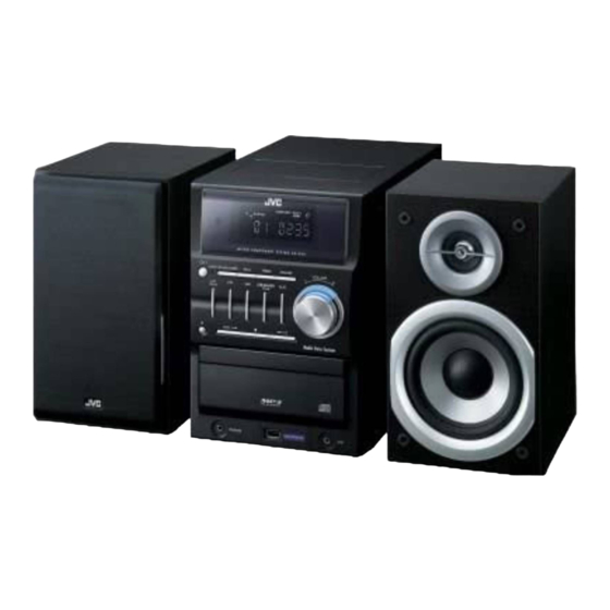
SERVICE MANUAL
MICRO COMPONENT SYSTEM
5 S ERVICE MANUAL
MB602
2007
UX-G46B, UX-G46E, UX-G46EN,
UX-G46EV, UX-G47E
SP-UXG46
COPYRIGHT © 2007 Victor Company of Japan, Limited
Lead free solder used in the board (material : Sn-Ag-Cu, melting point : 219 Centigrade)
1
PRECAUTION. . . . . . . . . . . . . . . . . . . . . . . . . . . . . . . . . . . . . . . . . . . . . . . . . . . . . . . . . . . . . . . . . . . . . . . . . 1-3
2
SPECIFIC SERVICE INSTRUCTIONS . . . . . . . . . . . . . . . . . . . . . . . . . . . . . . . . . . . . . . . . . . . . . . . . . . . . . . 1-6
3
DISASSEMBLY . . . . . . . . . . . . . . . . . . . . . . . . . . . . . . . . . . . . . . . . . . . . . . . . . . . . . . . . . . . . . . . . . . . . . . . 1-6
4
ADJUSTMENT . . . . . . . . . . . . . . . . . . . . . . . . . . . . . . . . . . . . . . . . . . . . . . . . . . . . . . . . . . . . . . . . . . . . . . . 1-13
5
TROUBLESHOOTING . . . . . . . . . . . . . . . . . . . . . . . . . . . . . . . . . . . . . . . . . . . . . . . . . . . . . . . . . . . . . . . . . 1-13
CA-UXG46
SP-UXG46
TABLE OF CONTENTS
COPYRIGHT © 2007 Victor Company of Japan, Limited
SP-UXG47
CA-UXG47
SP-UXG47
No.MB602
2007/5
Advertisement

Related Manuals for JVC UX-G46B


Summary of Contents for JVC UX-G46B
-
Page 1: Table Of Contents
SERVICE MANUAL MICRO COMPONENT SYSTEM MB602 2007 5 S ERVICE MANUAL UX-G46B, UX-G46E, UX-G46EN, UX-G46EV, UX-G47E SP-UXG46 CA-UXG46 SP-UXG46 SP-UXG47 CA-UXG47 SP-UXG47 COPYRIGHT © 2007 Victor Company of Japan, Limited Lead free solder used in the board (material : Sn-Ag-Cu, melting point : 219 Centigrade) TABLE OF CONTENTS PRECAUTION. - Page 2 SPECIFICATION 80 W per channel min. RMS driven into 6 Ω at 1 kHz with no Amplifier section Output Power more than 10% total harmonic distortion. (IEC268-3) 6 Ω - 16 Ω Speakers/Impedance Audio Input LEVEL1: 150 mV/47 kΩ (Input sensitivity/Impedance) LEVEL2: 500 mV/47 kΩ...
-
Page 3: Precaution
SECTION 1 PRECAUTION Safety Precautions (1) This design of this product contains special hardware and voltmeter. many circuits and components specially for safety purpos- Move the resistor connection to each exposed metal es. For continued protection, no changes should be made part, particularly any exposed metal part having a return to the original design unless authorized in writing by the path to the chassis, and measure the AC voltage across... - Page 4 1.5 Safety Precautions (U.K only) (1) This design of this product contains special hardware and many circuits and components specially for safety purposes. For con- tinued protection, no changes should be made to the original design unless authorized in writing by the manufacturer. Replace- ment parts must be identical to those used in the original circuits.
- Page 5 Important for laser products 1.CLASS 1 LASER PRODUCT 5.CAUTION : If safety switches malfunction, the laser is able to function. 2.CAUTION : (For U.S.A.) Visible and/or invisible class II laser radiation 6.CAUTION : Use of controls, adjustments or performance of when open.
-
Page 6: Specific Service Instructions
SECTION 2 SPECIFIC SERVICE INSTRUCTIONS This service manual does not describe SPECIFIC SERVICE INSTRUCTIONS. SECTION 3 DISASSEMBLY Main Body 3.1.1 Removing the side panel (See Fig.1, 2) (1) Remove the four screws A attaching the rear cover. (See Fig.1) (2) Remove the six screws B attaching the side panel . (See Fig.1) (3) Remove the four screws C attaching the side panel. - Page 7 3.1.2 Removing the top cover (See Fig.1, 3) (1) Remove the four screws D attaching the top cover and the side panel. (See Fig.3) (2) Remove the one screw E attaching the top cover. (See Fig.1) Caution: When take out the top cover, raise slowly, take care not to break the two claws of the front panel.
- Page 8 3.1.4 Removing the tuner pack (See Fig.5, 6) (1) Remove the two screws G attaching the tuner pack. (See Fig.5) (2) Disconnect the card wire from the connector CN351 of the main board. (See Fig.6) CN141 3.1.5 Removing the fan (See Fig.5, 6) (1) Remove the four screws H attaching the fan.
- Page 9 3.1.7 Removing the front panel assembly (See Fig.3, 4, 8, 9) (1) Pull out the tow connector wires a on the bottom chassis. (See Fig.4) (2) Remove the two screws N attaching the front panel. (See Fig.8) (3) Disconnect the connector wire from the connector CN860 of the CD board.
- Page 10 3.1.8 Removing the CD mechanism assembly (See Fig.10 to 12) (1) Remove the four screws P attaching the CD mechanism cover and then remove it. (See Fig.10) (2) Turn the gear c and then undraw the CD tray. (See Fig.11) (3) Remove the four screws Q attaching the CD mechanism assembly.
- Page 11 3.1.9 Removing the CD board (See Fig.9) (1) Remove the three screws R attaching the CD Board. (2) Disconnect the connector wires connected to the CD mechanism assembly from the connectors BN702, BN703 of the CD board. (3) Disconnect the card wire from the connector CN701 of the CD board.
- Page 12 3.1.12 Removing the VFD board (See Fig.15, 16) (1) Take out the volume knob. (See Fig.15) (2) Remove the four screws U attaching the VFD board. (See Fig.16) 3.1.13 Removing the key board (See Fig.16) (1) Remove the fourteen screws V attaching the key board. 3.1.14 Removing the jack board Volume knob (See Fig.16)
-
Page 13: Adjustment
SECTION 4 ADJUSTMENT This service manual does not describe ADJUSTMENT. SECTION 5 TROUBLESHOOTING This service manual does not describe TROUBLESHOOTING. (No.MB602)1-13... - Page 14 Victor company of Japan, Limited Audio/Video Systems category 10-1,1chome,Ohwatari-machi,Maebashi-city,371-8543,Japan (No.MB602) Printed in Japan...
- Page 15 PARTS LIST UX-G46B,UX-G46E,UX-G46EN UX-G46EV,UX-G47E * All printed circuit boards and its assemblies are not available as service parts. - Contents - 3- 2 Exploded view of general assembly and parts list (Block No.M1) 3- 5 Electrical parts list (Block No.01~04) 3-12 Packing materials and accessories parts list (Block No.M3)
- Page 16 Exploded view of general assembly and parts list Block No. Power Trans board VFD board Main board Key board Jack board...
- Page 17 CD board The parts without symbol number are not service.
- Page 18 General Assembly Block No. [M][1][M][M] Symbol No. Part No. Part Name Description Local BI372K30060YTN SCREW 3XL6(x2) BIBI3021970101 RUBBER FOOT (x4) BI372K30080NTN SCREW 3XL8(x2) BI1084880301X1 FRONT PANEL BI2031140101X1 CD DOOR SPRING BI372B20050NTN SCREW B HEAD(x4) BI1084220101X1 CD BAFFLE BI1084870201X1 CD DOOR SPRING BI1080800101V1 VOLUME KNOB ABS-T700 94HB...
- Page 19 Electrical parts list Main board Symbol No. Part No. Part Name Description Local Block No. [0][1] D236 1SS133 FR DIODE BI31SS133M000V7 Symbol No. Part No. Part Name Description Local D361 1SS133 FR DIODE BI31SS133M000V7 D362 1SS133 FR DIODE BI31SS133M000V7 D363 1SS133...
- Page 20 Symbol No. Part No. Part Name Description Local Symbol No. Part No. Part Name Description Local C242 BICE105500MP01 E CAPACITOR 1uF 50V C559 BICE475500MP01 E CAPACITOR 4.7uF 50V C243 BICC153500KA04 C CAPACITOR 0.015uF 50V C560 BICE475500MP01 E CAPACITOR 4.7uF 50V C244 BICC153500KA04...
- Page 21 Symbol No. Part No. Part Name Description Local Symbol No. Part No. Part Name Description Local R218 BIRM0022N25N00 M RESISTOR 0.22Ω 2W R407 BIRC1820085M00 C RESISTOR 1.8KΩ 1/8W R220 BIRC1030105A00 C RESISTOR 10KΩ 1/10W R408 BIRC2220085N00 C RESISTOR 2.2KΩ...
- Page 22 Symbol No. Part No. Part Name Description Local Symbol No. Part No. Part Name Description Local R528 BIRC6830105A00 C RESISTOR 68KΩ 1/10W R685 BIRC4730105A00 C RESISTOR 47KΩ 1/10W R529 BIRC2020105A00 C RESISTOR 2KΩ 1/10W R686 BIRC4730105A00 C RESISTOR 47KΩ...
- Page 23 Symbol No. Part No. Part Name Description Local Symbol No. Part No. Part Name Description Local S607 BI8SKRGAED0P0 TACT SWITCH SKRGAED010 C722 BICC474100KA04 C CAPACITOR 0.47uF 10V S608 BI8SKRGAED0P0 TACT SWITCH SKRGAED010 C723 BICC103500KA04 C CAPACITOR 0.01uF 50V S609 BI8SKRGAED0P0 TACT SWITCH...
- Page 24 Symbol No. Part No. Part Name Description Local Symbol No. Part No. Part Name Description Local R709 BIRC5620105A00 C RESISTOR 5.6KΩ 1/10W R870 BIRC1010085N00 C RESISTOR 100Ω 1/8W R710 BIRC1010105A00 C RESISTOR 100Ω 1/10W R871 BIRC1010105A00 C RESISTOR 100Ω...
- Page 25 Power trans board Block No. [0][3] Symbol No. Part No. Part Name Description Local IC901 BI101851X 78L05 Q903 KTC3199GR TRANSISTOR BI2KTC3199GP00 Q908 DTC114YS DIGI TRANSISTOR BI2DTC114YKA011 Q909 DTC114YS DIGI TRANSISTOR BI2DTC114YKA011 D901 1N4001 DIODE BI31N4001M0006 D902 1N4001 DIODE BI31N4001M0006 D903 1N4001 DIODE...
- Page 26 Packing materials and accessories parts list Block No. No additional / supplemental order of WARRANTY CARDs are available. A2, A3 UX-G46E, UX-G46EN,UX-G46EV, UX-G46B UX-G47E A4, A5, A6 The parts without symbol number are not service. 3-12...
- Page 27 Packing and Accessories Block No. [M][3][M][M] Symbol No. Part No. Part Name Description Local BI440001954000 INST BOOK ENG LVT1730-001A G46B BI440001955000 INST BOOK GER FRE ITA DUT LVT1730-002A G46E,G47E BI440001956000 INST BOOK SPA DAN FIN SWE POR LVT1730-003A G46EN BI440001957000 INST BOOK RUS HUN CZE POL LVT1730-004A...
- Page 28 SCHEMATIC DIAGRAMS MICRO COMPONENT SYSTEM UX-G46B,UX-G46E,UX-G46EN UX-G46EV,UX-G47E CD-ROM No.SML200705 SP-UXG46 CA-UXG46 SP-UXG46 SP-UXG47 CA-UXG47 SP-UXG47 Lead free solder used in the board (material : Sn-Ag-Cu, melting point : 219 Centigrade) Contents Block diagrams Standard schematic diagrams Printed circuit boards 2-7 to 9 No.MB602SCH...
- Page 29 In regard with component parts appearing on the silk-screen printed side (parts side) of the PWB diagrams, the parts that are printed over with black such as the resistor ( ), diode ( ) and ICP ( ) or identified by the " " mark nearby are critical for safety.
- Page 30 Block diagram SP201 [FRONT PCB-1] Main section SPEAKER Q243 VFD1 IC105 RELAY L-ch VFD DISPLAY AMP. CTRL X401 X402 RY201 8.0MHz 32.768kHz RELAY IC401 Q201,Q202 R-ch MICON +/-VP MUTE CTRL IC651 VFD DRIVER CN141 DC PROTECT Q144 SHORT Q402 PROTECT DRIVE RESET MOTOR...
- Page 31 Standard schematic diagrams Main section (1/3) DA01 DA23 C422 [2,3] VFD DISPLAY XRST TA[01:90] DA24 C423 DA02 DA03 DA11 C424 DA04 DA32 C425 VFD1 R488 DA44 C426 DA05 10K(A) 39 38 37 36 35 34 32 31 30 29 28 27 26 DA06 DA[01:85] R490...
- Page 32 Main section (2/3) FRONT2 TUNER PACK CN351 1SS335 D362 R364 E-VER : 15pin/2mm C376 C362 R392 4.7K 1SS335 D363 Other Ver : 11pin/2mm 2.2U/50(3*5) 3.9K 2.2U/50 0.1U C369 Q371 R371 R376 DTC124EK R357 R380 100(A) 4.7K Q362 R356 DTC323TK J-AX C355 47K(A) 0.01...
- Page 33 Main section (3/3) TA37 BC-CNT C203 4.7K R203 IC105 L-CH STK433-090 1U/50 R205 2.2K R2686 Q201 470K DTC323TK A-GND Q202 DTC323TK C242 R206 C204 1U/50 2.2K 1U/50 R204 4.7K R-CH R262 D232 R285 C241 R220 R260 Q204 DTA114YK TA81 10U/50 1SS133 RY201 D201...
- Page 34 CD section R747 R813 R701 C826 C732 BN803 100(A) 10U/16 CON-ASSY2.0-8P L808 0.1U PICK-UP CD-Rch F BEAD UNIT A GND R812 R746 C724 C827 10U/16 C733 CD-Lch 100(A) C703 L822 0.01U CN701 0.1U RM[01:50] D GND F BEAD FFC-1.0mm-16P 1000P R724 M GND VREF...
- Page 35 Power section Q909 DTC114YS Q908 DTC114YS P/T PCB BN101 CON-ASSY2.5-4P CN902 C908 AMP AC CON-7.92-2P C907 R905 4700P R907 3.3U/50 AC 230V AC 230V RY901 1.2K(A) RELAY COMMON R903 COMMON AMP AC 3.3K(A) BN903 R904 CON-ASSY2.0-6P AC 12V DETECT IC901 C906 NJM78L05 MICOM 5V...
- Page 36 Printed circuit boards Main board Lead free solder used in the board (material : Sn-Ag-Cu, melting point : 219 Centigrade) reverse side forward side (Key board) (Connection board 1) (Connection board 2) (Main board) (VFD board) (Jack board) C626 IC625 C413 J445 D405...
- Page 37 CD board Lead free solder used in the board (material : Sn-Ag-Cu, melting point : 219 Centigrade) reverse side forward side BN703 X860 JW768 L809 R836 R814 C816 R811 4.GND JW767 C835 R876 3.D+ C822 2.D- 1.M+5V R889 C812 R877 C811 R878 C813...
- Page 38 Power trans board Lead free solder used in the board (material : Sn-Ag-Cu, melting point : 219 Centigrade) PT902 T1.25AL 250V F901 FC902 FC901 C907 LIVE NEUTRAL R905 AC IN Q903 R906 D901 C904 CAUTION: D902 RY901 D903 REPLACE WITH SAME TYPE AND RATING FUSE(S).
- Page 39 Victor Company of Japan, Limited Audio/Video Systems Category 10-1,1chome,Ohwatari-machi,Maebashi-city,371-8543,Japan Printed in Japan (No.MB602SCH)