Table of Contents
Advertisement
Quick Links
Please use the following steps as a guide to set up and begin successfully using your new SOLO:
Step 1: Unpack your SOLO and verify nothing is missing
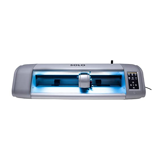
Step 2: Note the names of various parts of your SOLO for future reference
Step 3: Install the CREATE software and register it
Step 4: Power on the SOLO and note the basic settings on the control panel
Step 5: Connect the SOLO to your computer after reviewing the connection options
Step 6: Check out the other accessories which came with your SOLO
Step 7: Adjust the pinch rollers to their proper positions
Step 8: Practice drawing a shape using the test pen
Step 9: Understand some important factors and settings before cutting with the blade holder
2.01 –
2.04).
Step 10: If you plan to perform Print+Cut applications (aka contour cuts), calibrate the camera and
set up your first project
Step 11: Some of the more commonly used CREATE functions are presented in
complete
StarCraft CREATE User Manual
here in this manual pertain to the
Step 12:
Appendix A
is a troubleshooting section for issues involving communication, operating,
cutting, and the CREATE software.
not ever need.
Latest Update to StarCraft SOLO Manual: https://tinyurl.com/pbmam6eu
Latest Update to StarCraft CREATE User Manual: https://tinyurl.com/46wnn3ck
_____________________________________________________________
© 2021, 2022
starcraftvinyl.com All Rights Reserved
StarCraft SOLO with CREATE 1.008
January 18, 2022 Version
(Sections 3.02 and
3.03).
can be found at the link below. Note that references in
CREATE
manual.
Appendices B – E
(Sections 1.01 and
(Section
1.06).
(Section
(Section
1.10).
(Section
1.11).
contain advanced topics that you may or may
1.04).
(Section
1.05).
(Section
1.07).
(Section
1.08).
1.09).
(Sections
Chapter
4. A
blue
1
Advertisement
Table of Contents
Troubleshooting

Summary of Contents for Starcraft SOLO
-
Page 1: Starcraft Solo With Create 1.008
StarCraft SOLO with CREATE 1.008 January 18, 2022 Version Please use the following steps as a guide to set up and begin successfully using your new SOLO: Step 1: Unpack your SOLO and verify nothing is missing (Sections 1.01 and 1.04). -
Page 2: Table Of Contents
UTTER 1.06 I CREATE ......................... 8 NSTALLING RAFT 1.06.1 Downloading and Registering CREATE ................8 1.06.2 Installing the SOLO in CREATE ......................9 1.07 C ..........................10 ONTROL ANEL 1.07.1 Set Screen ............................10 1.07.2 General Settings ..........................11 1.08 C SOLO ..................... - Page 3 3.05 S ..................52 ETTING AN RIGIN SING THE AMERA 3.06 A ........................54 DDITIONAL RINT OTES 4. STARCRAFT CREATE SOFTWARE ....................... 55 4.01 M CREATE S ..........................55 CREEN 4.02 C ..................57 OMMON REFERENCES AND CREEN OOLS 4.02.1 Common User Preferences ........................ 57 4.02.2 Screen Tools ............................
- Page 4 6.02. S ......................86 ETTING ROCESSES 6.03 D ..........................86 RAWING WITH A 6.04 S ..................87 CORING INES AND EBOSSING MBOSSING 6.05 S ..........................88 CRATCH NGRAVING APPENDIX A TROUBLESHOOTING ........................89 A1 C ..........................89 OMMUNICATION SSUES A2 O ............................
-
Page 5: Introduction And Setting Up
USB Cable: If using the USB cable, allow enough room between the SOLO and the computer for a bit of slack in the cable. If too much stress is put on either the computer’s port or the SOLO’s port, it can damage the port. -
Page 6: Warranty
Always turn off the SOLO before unplugging the power adaptor or removing the power cable from the wall outlet or power strip. • Unplug the SOLO from a wall outlet or power strip during an electrical storm or when the cutter will not be used for an extended period of time. •... -
Page 7: Parts Of The Solo Cutter
• USB Flash Drive Port: used to load PLT files via the control panel for cutting • USB Port: option to connect computer to the SOLO with included USB cable Power Port USB Flash •... -
Page 8: Installing Starcraft Create
• Write down your SOLO’s serial number which is on the bottom of the cutter. In the registration window, enter this 9-digit serial number in the upper gray field. Click on Get CREATE Serial and a 30-digit CREATE Serial Code will appear: 1. -
Page 9: Installing The Solo In Create
Project Accept whatever settings are shown. Details about these settings will be covered in later sections. 1.06.2 Installing the SOLO in CREATE • Go to Cutter>My Cutter>Manage Cutters and the following window will open: 1. Select StarCraft List of cutters you’ve added... -
Page 10: Control Panel
• The SOLO will take a few seconds to power up. A splash screen will appear. Then the LED light will come on and the tool carriage will engage. IMPORTANT: Once the cutter is on, do not move the tool carriage using your hands. -
Page 11: General Settings
LED set allows you to change the color of the light inside the SOLO. The default is white but you can change it by dragging the scroll bars on the LED set screen. For example, if you wanted a blue light, you could drag red and green all the way to the left. -
Page 12: Connecting The Solo To Your Computer
Language allows you to choose from twelve languages for the control panel display screens. 1.08 Connecting the SOLO to Your Computer • There are 4 ways that you can connect your SOLO to the computer. Review the information in the following table to understand the differences between these options: •... -
Page 13: Usb Connection
• Note: Not all routers have the same signal strength. It’s usually best to connect the SOLO while it is in the same room with the router. Once connectivity is established, you can then experiment to see how far from the router the SOLO can be located. - Page 14 1. Select your network 3. Click on Set 2. Click on Apply (3) Click on Set and the following screen will open: Password will display here Switch to numbers Switch to punctuation Delete last Toggle to switch between character uppercase and lowercase letters Click OK when done (4) To enter the password, use the following tips if you are unfamiliar with this type of screen:...
- Page 15 Range: 150 - 250 (6) Next check the IP Address that will be assigned to the SOLO. The SOLO will automatically pick up the first three sets of digits from your router but will continue to display them as shown above. You only need to decide if the last set, which should be defaulting to “200”, can be used.
-
Page 16: Accessories
• If the SOLO is successfully connected to your computer, pressing Test Conection will cause the cutting head to do a quick left-right jog. Note that it is natural for there to be a slight delay in response when the connection is first established after powering on. -
Page 17: Cutting Mat
• Do not leave the pinch wheels in a down position when the SOLO isn’t in use. This warps the plastic sooner, shortening the useful life of the cutting mat. -
Page 18: Begin With The Test Pen
1.11 Begin with the Test Pen! • Before cutting with the blade, start with the test pen and have the SOLO draw some shapes onto a sheet of paper. This is important so that you can become familiar with the following: ... - Page 19 • Use any of the horizontal markings along the front of the SOLO to align the mat (or paper) so that it’s straight. Lift the pinch lever to drop the pinch wheels onto the cutting mat (or paper).
-
Page 20: Setting An Origin Before Drawing (Or Cutting)
Before you draw (and later on, before you cut), an origin needs to be established which is nothing more than positioning the location of the test pen (or blade holder) over the material. • The arrow keys on the SOLO’s control panel are used to set the origin: The middle button can be toggled so that the... - Page 21 Click here Select Mat Size to match your paper Select Vertical (Portrait) dimensions • If you closed the Library when you opened CREATE, click the Library icon at the top of the screen to reopen. Click on the Arrow thumbnail to add that shape to your screen. An arrow will help you better compare where a shape gets drawn versus how you see it on the screen: Click on this arrow •...
- Page 22 2. Click on the arrow layer on the Layers Panel 3. Click on this icon 1. Click on this icon (Style Panel) (Style Panel) • Change the Cut Line Type from Cut to Draw: Change to Draw • Open the Cut Settings window by clicking the CREATE icon in the upper right corner of the screen: Click here to zoom out...
- Page 23 • If you completed the steps in Sections 1.06 and 1.08, then Model should indicate SOLO and the Connection should be set to whichever method you elected to use. • Set the Cut Mode to WYSIWG (What You See Is What You Get) as indicated in the prior screenshot.
-
Page 24: Maintenance
Manual. 1.12 Maintenance • SOLO cutters contain internal lubrication to protect all mechanical parts. Therefore, there is no need to oil or lubricate any of the components. • Keep the cutting mat clean and sticky by washing with warm water or using baby wipes. -
Page 25: Cutting
2. Cutting To be a successful owner of a SOLO, you need to keep in mind a few factors: • You’re going to make mistakes. This is normal and part of the process of mastering a cutter. • Read this chapter. It contains valuable information to help you understand how to load the blade, set the exposure, understand the effects of various cut settings, create presets, and set a new origin. - Page 26 Rim is resting on the seat – used in normal cutting without the mat or cutting most thin materials with the SOLO mat. If the blade is scratching the surface, check these two things: The blade exposure isn’t more than needed to penetrate the material The mat isn’t drooping so much that there is significant bowing where the blade is cutting (you may...
-
Page 27: Setting The Origin Before Cutting
• IMPORTANT! The SOLO has a maximum cutting width of 16 inches. If you move the head too far to the left to begin the cut and your project is wide, you may exceed the left side limit and cutting will stop at that point, activate a red light, and begin beeping. -
Page 28: Controlling Where Shapes Will Cut
• The SOLO, on the other hand, has a home origin in the lower right corner (diagonally opposite). Thus, it is recommended that the design be located near the bottom right corner in CREATE and the blade be placed... - Page 29 Mat Size (also called the Page Size) dimensions selected on the Document Panel match the material dimensions you plan to use in the cutter (versus, say, the 12” x 19” SOLO mat or other size). This will help you better learn where shapes will cut on the SOLO.
-
Page 30: Style Panel Assignments
Portrait + Origin Point Page Cut Settings preview Material based on origin set here Portrait + Center Point Shape is cut so that its Origin is set somewhere Page center is aligned with the well inside the material origin that was set •... - Page 31 Shadow will apply a contour cut (outline) to a shape which is a fast way to create one without making it a permanent addition in your project (otherwise, refer to Section 7.05 of the StarCraft CREATE User Manual). Blackout will remove all interior paths from a closed shape.
-
Page 32: Preview The Project
Color layer alignment: In applications such as vinyl, where several layers will be cut from different colors and aligned, choose this option for a layer that has alignment shapes that need to be cut from every color along with that color’s shapes. The Cut by Color tab in the Cut Settings window can then be used to select which colors will be cut and in which order. -
Page 33: Determining Cut Settings
• NOTE: If you mark the option for Show Print+Cut registration marks and they do not appear: Verify that you have set up the SOLO (refer to Section 1.06.2) Verify that all layer(s) you wish to view are not hidden on the Layers Panel ... -
Page 34: Pressure
• On the SOLO control panel, the default setting is to have the Up Speed and Cut Speed the same and referred to as SPEED. This can be adjusted by pressing the Force/Speed icon and setting the SPEED to the desired level. -
Page 35: Multi-Cut
• Currently it is recommended that a Blade Offset of 0.3 be used for all SOLO blades. • Overcut is related to Blade Offset in that it isn’t needed when using a pen because the tip is aligned with the center of the pen. -
Page 36: Landscape Cutting
Click on OK • After clicking on OK, the new preset will be found at the bottom of the list. • Presets can also be saved on the SOLO control panel. Refer to Appendix D. 2.06 Landscape Cutting • Landscape orientation works well when cutting long projects. It allows a better view of the project on the... - Page 37 Arrow is at the top versus Arrow is on the left Vertical (Portrait) Horizontal (Landscape) • As with Portrait orientation, controlling where shapes will cut is a combination of the Landscape orientation and the Cut Mode setting in the Cut Settings window. Note the Preview has rotated the cutter: Landscape + WYSIWYG Page Cut Settings preview...
-
Page 38: Other Cut Options Of Interest
Landscape + Center Point Page Origin is set somewhere Shape is cut so that its well inside the material center is aligned with the origin that was set 2.07 Other Cut Options of Interest 2.07.1 Mirroring Designs Before Cutting • CREATE offers two methods for mirroring designs for applications such as HTV or vinyl decals for the inside of a window. -
Page 39: Setting Up An Array Of Repeats
Click OK when Columns and Total Rows. done. • More about the Duplicate function is covered in Section 3.17.4 of the StarCraft CREATE User Manual. • CREATE also has a nesting feature to economize on material usage. To activate, go to Effects>Nest:... -
Page 40: End Of Cut Action
2.07.3 End of Cut Action • The End of Cut Action is set on the SOLO’s control panel. The function, which has 3 options, is opened by going to Set>Advance Mode. Its three options control what happens when a cut is completed:... - Page 41 Click on this tab Select either Cut all colors or Fill color or Stroke Cut each color separately color option Fill colors used in the project Option to Check All or Uncheck All colors listed • Cut all colors (Single job): In this mode all of the colors marked in this window will be cut at one time. You can click on the blade icon to turn off any color(s) not to be used in the cut.
- Page 42 Color to be cut Preview of shapes to be cut from this color Option to skip this color Cancel cutting all colors Click on Cut to proceed If you decide not to cut this color, click on Skip Job and the next color in the menu will be selected. If you clicked on Cut, then the shapes shown in the Preview will be cut and the next color in the menu will be selected.
-
Page 43: Weeding
Tiling is used to break up a design into rectangle shapes when the design is wider than what can be cut on the SOLO. • StarCraft CREATE User Manual. For details on how to tile a large design, refer to Section 8.07... -
Page 44: Test Cutting Flow Chart For The Solo
2.08 Test Cutting Flow Chart for the SOLO The following flow chart can be used to identify which settings should be adjusted after a test cut (or even a complete project cut). Based on the cut, pick a path (A, B, C, or D) and perform recommended changes and then repeat the test cut. -
Page 45: Suggested Cut Settings For Various Materials
5. Condition of the cutting mat, if using one (tackiness, even or slightly warped) 6. Conditon of the cutting strip on the SOLO (new or scratched up, evenly pressed down or uneven) 7. Intricacy of the design (large basic shapes vs small lettering vs perfectly round circles, etc.) •... -
Page 46: Print+Cut (Contour Cut)
Solo test pen (remove the wax on the nib) (1) Place the sheet of paper into the SOLO. You can use the cutting mat to hold the paper or insert the paper directly. (2) Mount the test pen into the SOLO so that the nib is slightly above the paper. - Page 47 1. Select Adjust 2. Press and hold OK 3. Release after 4. Press Start buttons turn red (7) Press Start. The test shape, which is a grid of 6 lines, will be drawn on the paper and the camera will move over the test shape, take a photo, and display the photo on the control panel.
-
Page 48: Performing Apnc In Create
Everything is aligned with the center Arrows are white again Press Home (10) If the arrow buttons are still red, repeat the prior two steps. (11) Once the arrow buttons are white, press the Home button and then press Stop on the Main Screen to save the calibration and conclude the process. - Page 49 (3) On the Layers Panel, click on the triangle icon to open the grouped layer to see that there is both a cut layer and a print layer within that group: Two layers Click on triangle (4) When you select just one of the two layers and look at the assignment on the Style Panel, you’ll see that the Cut layer is assigned as Cut and the Print layer is assigned as Print+Cut Print.
- Page 50 Four reg marks surround the design to be printed Print area based on your printer’s current settings (7) Click on the CREATE icon to open the Cut Settings window. Click on the Print+Cut icon in the lower left corner: Click on Print+Cut (8) The Print and Cut window will open: 1.
- Page 51 (11) Insert the mat into the cutter, aligning one of the grid lines with the Solo’s cutting strip or the front horizontal groove visible through the mat. The alignment doesn’t need to be perfect, just close enough that it makes for a faster and, of course, successful detection by the camera.
-
Page 52: Registration Mark Settings
Mark Offset or Inset distance Mark type: The SOLO’s camera uses four marks; thus, this option will always remain the same. Mark size: The default size of 1.50 cm is advisable if the material is angled a bit with respect to the cutter or if the material isn’t flat. - Page 53 (3) On the SOLO’s Main Screen, use the arrows to move the center of the blade holder roughly over the origin target. In this example, a dot will be used.
-
Page 54: Additional Print+Cut Notes
Properties. Refer to the last bullet in Section 3.04. • If you need instructions on loading a Print+Cut project from a USB flash drive inserted into the SOLO’s control panel, refer to Appendx C2 followed by Appendix •... -
Page 55: Starcraft Create Software
4. StarCraft CREATE Software • This chapter covers just those functions in StarCraft CREATE that are most commonly used. Again, section numbers refer to this user manual while blue reference numbers refer to the StarCraft CREATE User Manual. 4.01 Main CREATE Screen •... - Page 56 • Tools Panel Selection Tool: click or drag mouse to select shapes 3.02 Selection: drag a path to lasso-select shapes 3.02 Shape Tool: edit nodes and reshape paths 6.11 Type Tool: Enter text with options for vertical text, type on path, and type on arch 4.08.1, 4.04.1 Draw Tool: Add straight lines and Beziér curves;...
-
Page 57: Common User Preferences And Screen Tools
4.02 Common User Preferences and Screen Tools 4.02.1 Common User Preferences There are a number of preferences that will affect your experience as you learn CREATE. They are presented here for your consideration: • Document Panel preferences: Units Show Grid ... -
Page 58: Screen Tools
Name the new Workspace Click on OK Before closing CREATE, make sure you select your new Workspace under Window>Spacespace. 4.02.2 Screen Tools • Zooming and Panning: The Tools Panel offers both a Zoom Tool and a Panning Tool . There are also some shortcut keys that you may prefer: ... -
Page 59: Projects And
• Further details on organizing and fully utilizing the Library are covered in Section 2.03 of the StarCraft CREATE User Manual. 4.04 Projects and Pages • The Project Bar is located right above the Ruler and shows what projects (files) are open and have been saved and new projects that have been started but not named: Project that hasn’t... -
Page 60: Layers Panel
This is covered in the following sections of this manual, with more details in Section 2.04 of the StarCraft CREATE User Manual. 4.05.1 Parts of the Layers Panel • This section will use the following simple project to illustrate the Layers Panel:... - Page 61 • The following screenshot identifies the various icons on the Layers Panel: Layer Type Layer Thumbnail Click to display the Layer Color Layers Panel Hide/Show Layer Layer Name: double click to change name and/or properties Lock/Unlock Layer Add a layer folder Delete selected layer •...
-
Page 62: Moving Layers
Layer Color: Click on the current layer color icon and a Color window will open where a different color can be assigned. Again, this is only for making layers easier to distinguish on the Layers Panel and doesn’t change the Fill or Stroke color of the shapes themselves. •... - Page 63 Note new thumbnail image If, instead, you drag a layer while moving it to the left, you will see a longer line with a closed black square. This means it will be added directly above that line: Long line with closed square: Asterisk layer will be relocated just above the Spring layer Layer being dragged upwards ...
- Page 64 Click here to Only drag this layer open folder Then drag the yellow layer up to the Yellow Shapes, again making sure only a short line is present. The yellow layer is then moved out of the Flower 2 group: Short line –...
-
Page 65: Handling Files
As with other CREATE functions, this manual only touches upon the basics. For more information on the many ways in which you can color and manipulate shapes, refer to Chapter 3 of the StarCraft CREATE User Manual. 4.07.1 Fill & Stroke Panel •... -
Page 66: Resizing, Rotating And Moving Shapes
Color: Clicking the box to the right of Fill opens a window where you can set a new color, including adding your own custom colors. Pattern: CREATE comes with a choice of 7 patterns but you can upload your own images to use as patterns. -
Page 67: More Shape Manipulations
4.07.3 More Shape Manipulations • Because CREATE has many functions to use when editing shapes, the following table shows examples of each function and where to locate in both the CREATE program and in the StarCraft CREATE User Manual: Name Image... -
Page 68: Text
As with other CREATE functions, this manual only touches upon the basics. For more information on the many customizing features you can apply to text, refer to Chapters 4 and 7 of the StarCraft CREATE User Manual. 4.08.1 Type Tool Options •... -
Page 69: Changing The Font
For instructions on using the other 3 modes, refer to Section 4.04 of the StarCraft CREATE User Manual. 4.08.2 Changing the Font • You can change the font used on a selected text object by accessing the font menu on the Text Panel or under Text>Font or on the Fonts tab in the Library. -
Page 70: Text Panel Settings
Ignore: The text with the missing font will be converted to an outline (no longer editable as a text object) Replace: The text will be replaced with the font shown or another font you select from the drop- down menu 4.08.3 Text Panel Settings •... -
Page 71: Tracing And Drawing
Sections 5.01 – 5.03 cuttable file. This is a powerful tool in CREATE and is covered in detail in of the StarCraft CREATE User Manual. • On the Toolbar, click the Trace Image icon to open the Trace Image window: 1. -
Page 72: Image Settings
Clicking Update Preview to check the tracing based on current settings Making changes to the Image Settings and Output Settings to optimize the trace Selecting OK to move the results to the Page • To begin the process, click on Choose an image to import the image you wish to trace. Alternatively, File>Place Image in the main window can also be used and, with that image selected, clicking on the Trace Image icon will automatically import the image into this window. - Page 73 Tracing ungrouped Original image Tracing of image if each and separated color is selected • Each Mode has its own setting which affects what gets traced: Monochrome: Increase Contrast to trace more, decrease Contrast to trace less: Adjust Contrast Original Image Contrast: 5 Contrast: 75...
-
Page 74: Output And Output Settings
High Pass Filter can be used with photographs and other challenging images, but requires a considerable amount of tweaking. Examples of all three of these settings are covered in Section 5.03 of the StarCraft CREATE User Manual. 4.09.3 Output and Output Settings • The Output section provides the following: ... -
Page 75: Editing Tools
Draw Tool: Use this function to create straight lines and Bézier curves. Hold the Shift key to force lines to be horizontal, vertical or at a 45°angle. Press Enter to conclude a line or curve. Freehand Drawing: Freely draw thin lines with a Smoothing setting to help with shaky hands. ... -
Page 76: Designing
SVG file into a template. Refer to Section 7.04 of the StarCraft CREATE User Manual. • The following table shows samples of the designing effects at your disposal. Note that with almost every effect, there are unlimited ways to create variations by adjusting settings, colors, and/or selected images:... - Page 77 Knockout Effects>Knockout 4.12 7.23 Lattice Effects>Lattice 7.11 Line Fill (for engraving or Effects>Line Fill 8.09 coloring in) Nest Effects>Nest 8.11 Object on Path Effects>Object on Path 7.09 Pierce (punch Effects>Pierce 8.10 holes) Puzzle Generator Effects>Puzzle Generator 7.13 QR Code Effects>QR Code 7.22 Rhinestones Effects>Rhinestones...
-
Page 78: Applications And Tips On Materials
• Check the mat after a test cut to make sure it hasn’t cut more than a faint line. The Test button on the SOLO cuts a circle inside of a square which is ideal because you can check to see if the circle cut into the mat without needing to lift a corner of the cardstock away from the mat to check. -
Page 79: Adhesive Vinyl Tips
The lines do not need to be vertical and horizontal; angled lines can also be used. Refer to Section 8.06 of the StarCraft CREATE User Manual. • If the vinyl design is to be applied to the inside of a window so that the main viewing will be from the other side, you’ll need to mirror the design. -
Page 80: Weeding
In general, it’s best not to layer HTV when applying. Thus, with overlapping colored shapes in a design, you’ll want to cut one shape from another. Use the Knockout function presented in Section 7.23 of the StarCraft CREATE User Manual. • For easier weeding of the waste from the backing sheet, add some weeding lines. -
Page 81: Cutting And Weeding
It’s a good idea to write a reminder ("Have your mirrored your image?") and stick it somewhere on your SOLO where you will see it. Definitely a money saver! Cutting and Weeding • HTV consists of three layers:... -
Page 82: Adhering Htv
Adhering HTV • Always refer to the manufacturer’s recommended instructions for temperature, press time, peel time, and laundering. • You can use a home iron for applying HTV. Here are a few tips: Use a hot dry iron (cotton setting), with steam turned off. ... -
Page 83: Cake Decorating Tips
Templates from thin chipboard to use as patterns when cutting thick layers of gum paste • Icing sheets can be cut on the regular SOLO mat, although it’s a good idea to have one dedicated to cake use only. The same is true for the blade holder and blade. -
Page 84: Chipboard Tips
• The SOLO offers some very slow speeds and cutting chipboard may require these. Don’t hesitate to reduce the speed to a setting of 4 or slower, if you find the cutter is struggling to cut the chipboard or the shapes being cut are distorted. -
Page 85: Accessory Tools
(such as nickel or a quarter) or anything else with about that thickness. Then, after loading your material into the SOLO, place the spacer on top of the material and mount the accessory tool so that the tip is touching the top of the spacer before you tighten the front screw: •... -
Page 86: Setting Up Two-Step Processes
This will be shown in the step-by-step tutorials. 6.03 Drawing with a Pen • With the SOLO, you can draw shapes and lettering with the test pen or a pen/marker which fits into a 3 party penholder. •... -
Page 87: Scoring Fold Lines And Debossing/Embossing
6.04 Scoring Fold Lines and Debossing/Embossing • The SOLO Scorer/Debossing tool has two heads which are identical. This tool can be used when creasing cardstock for fold-up projects, such as pop-up cards, gift bags, and small boxes. It can also be used for debossing or embossing shapes. -
Page 88: Scratch Engraving
If possible, test on scraps first. • Note that you can engrave on materials that cannot be cut on the SOLO, such as jewelry charms, dog tags, and trophy plates. These items need a strong double-sided adhesive tape to adhere to the cutting mat. -
Page 89: Appendix A Troubleshooting
Make sure the power cable is securely plugged into the adaptor and into a wall socket or power strip. • Make sure the adaptor light is a steady green light and it is plugged securely into the SOLO. • If you still cannot get the SOLO powered on, contact your dealer. -
Page 90: A2 Operating Issues
I had to cancel a cut. Now my SOLO is no longer responding when I click on CREATE to cut. • In the Cut Settings window, check the setting for Connection. For example, it may have reset to USB whereas you had your SOLO setup wirelessly and need TCP/IP selected. - Page 91 ____________________ The SOLO stopped during a cut. • If the SOLO stops with the blade carriage near the left side of the cutter, you have most likely exceeded the cutting range. Several things to consider: Check the width (W) of your project (or the height H if in Landscape mode). It cannot exceed 15.75”.
-
Page 92: A3 Cutting/Drawing Issues
Make sure it’s not a communication issue. For cuts which take a long time to complete, a USB connection or saving your file in PLT format onto a flash drive to load directly into the SOLO is recommended. ... - Page 93 ____________________ I’m drawing with a pen and there are bubbles at the corners. • For perfect corners when using a pen, turn off Blade Offset (set to 0) since you do not need an offset for pens (or other tools like embossers and engravers). Alternatively, set those layers being drawn to Draw on the Style Panel and set Holder to Pen in the Cut Settings window.
- Page 94 You may have too many nodes in the shape. Refer to Section 6.01 of the StarCraft CREATE User Manual. The material itself may be subject to tearing, especially on intricate cuts. Also, if the cardstock has been exposed to humidity, then the moisture in the material can make it difficult to cut cleanly. You can dry paper and cardstock using a blow dryer or in a very low-temperature oven.
-
Page 95: A4 Software Issues
• If there are fonts you wish to have installed in CREATE only, then copy/paste those font files into Document\StarCraft CREATE\My Fonts. They will then become a part of the Font menu in CREATE. ____________________ I’m trying to use the Pattern Fill feature to fill some shapes with a digital scrapbooking paper file. The pattern doesn’t look right. - Page 96 Copy and paste those two folders to a new location outside of the StarCraft CREATE folder. Delete all files in those two folders that are still in the StarCraft CREATE folder. Verify that you can now open CREATE successfully. If not, start a support ticket. Otherwise, you can now begin copying/pasting back the older files based on their Modified Date since it’s most likely a...
-
Page 97: Appendix B Control Panel Advanced Settings
In the above screenshot, the shape sent to the SOLO would cut 3 across and 7 up & down, for a total of 21 shapes. The spacing between each shape would be 0.20 inches (Note: to use mm instead of inches, switch the Units setting. - Page 98 Secondary Location Primary Location Press on top of the numbers to Press on top of the numbers to return to the Secondary Origin return to the Primary Origin Short press to reset Secondary Origin or… Long press to reset both Press here to toggle speed control Origins •...
-
Page 99: B3 U Pspeed
B4 To right power on • With this setting turned on, the cutting head will move to the far right whenever the SOLO is powered on. Otherwise, the cutting head remains in the same location as when the SOLO is powered off unless you move the head manually while off. -
Page 100: B7 Scale
250 mm: Set to Mm Change sizing here • On your SOLO control panel, go to Set>Advanced Settings> Scale. The following window opens where you can verify that the current X Scale and Y Scale values are both set to 1.0000:... - Page 101 (the left-to-right length that drew) and the Height (the top-to-bottom length that drew. Note that it doesn’t matter if you had Portrait or Landscape selected in CREATE. It’s the same as shown below: Feed the mat this direction into the SOLO Width, X Height, Y •...
- Page 102 Scale screen instead of the 1.0 that was originally used in the prior calculations • Once you have your calibration set, please record these values in your “little black book” in case you ever need to reset your SOLO to default settings or install a firmware update.
-
Page 103: Appendix C: Alternative Connection Methods
SOLO can be located. • There are two situations to consider before getting started. If you are not sure which applies to your SOLO, then select B and go to that section first. -
Page 104: C2 Usb Flash Drive
• To reset the SOLO so that it will be found as an available network, press and hold the Default button for 3 seconds. Release and you should see the Apply button now displays Wait. In a minute the Apply should return and you can then proceed back to A and use the same procedure as if the SOLO was never set up on a network. - Page 105 Reg Marks will be needed. The file will then be saved as PLT. (4) Insert the flash drive into the right side of the SOLO. On the control panel, select USB and then Open...
- Page 106 Double tap on selected file to go back to USB screen (7) If you wish to cut repeats of the file, select Array Set and a screen will open where you can then select the number of rows and columns of repeats, along with the spacing between the repeats. Refer to Appendix B1.
-
Page 107: Appendix D Creating Presets On The Control Panel
Appendix D Creating Presets on the Control Panel • Besides in CREATE’s Cut Settings window, presets can also be saved on the SOLO control panel. However, they only include Force, Cut Speed and Up Speed, if Up Speed is set to show (refer to Appendix B3). - Page 108 New preset name will display here Switch to numbers Switch to punctuation Delete last Toggle to switch between character uppercase and lowercase letters Click OK when done You will now see the name of your new preset and you can press Save to add it to the saved presets with the FORCE and SPEED you set.
- Page 109 Select Preset Select Rename to Select Load to change edit the name Speed and Force to these settings...
-
Page 110: Appendix E Additional Print-And-Cut Applications
APPENDIX E Additional Print-and-Cut Applications E1 PNC from a Flash Drive • To perform a Print+Cut project from the control panel, first perform Steps (1) – (6) from Section 3.03. • When you are ready to print the project, go to File>Print and mark the option for Print registration marks before clicking OK to print the project: 1. - Page 111 The alignment doesn’t need to be perfect, just close enough that it makes for a faster and, of course, successful detection by the camera. • Place the blade holder into the SOLO and move the head until the blade holder is over the lower right printed registration mark as shown in the prior screenshot. •...
-
Page 112: E2 Printing Apnc Project From Outside Of Create
File name should appear here Press Start Cut Assuming the printout is on the cutting mat and the blade holder is over the lower right registration mark, click on Start Cut and the marks will be scanned by the camera and the shapes cut out. E2 Printing a PNC Project from Outside of CREATE •... -
Page 113: E3 Tweaking The Camera Calibration
IMPORTANT: If a cutter has not yet been set up in CREATE, reg marks will not be Select a PDF printer option printed. Thus, make sure you have gone through Section 1.06.2 before doing this step. Click on OK Mark this option For Mac owners: Go to File>Print and mark the option for Print registration marks. - Page 114 • Go to Set>Camera and click on Adjust. Then click on Set to open the Adjustment window: 2. Then press Set 1. Press Adjust 3. Press and hold on top of Δx and Δy • Δ Δ Press your finger on top of the x and y values to activate the direction buttons.
Need help?
Do you have a question about the SOLO and is the answer not in the manual?
Questions and answers