
Related Manuals for LUDLUM 14C


Summary of Contents for LUDLUM 14C
- Page 1 LUDLUM MODEL 14C SURVEY METER July 2022 Serial Number 260716 and Succeeding Serial Numbers...
- Page 2 LUDLUM MODEL 14C SURVEY METER July 2022 Serial Number 260716 and Succeeding Serial Numbers...
-
Page 3: Table Of Contents
Model 14C Survey Meter Table of Contents Introduction Getting Started Unpacking and Repacking Battery Installation Connecting a Detector to the Instrument Battery Test Instrument Test Reading the Meter-Face Dial Operational Check Specifications Identification of Controls and Functions Safety Considerations Environmental Conditions for Normal Use... - Page 4 Model 14C Survey Meter Parts List Model 14C Survey Meter Main Board, Drawing 464 × 454 HV Power Supply Board, Drawing 464 × 302 Wiring Diagram, Drawing 464 × 175 Drawings and Diagrams...
-
Page 5: Introduction
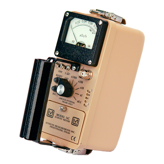
Model 14C Survey Meter 1. Introduction he Model 14C is a rugged, portable survey instrument that operates on two standard "D" cell alkaline batteries. The instrument features a regulated high voltage power supply set at 900 volts and provides five linear ranges for measurement from 0 to 2000 mR/hr. -
Page 6: Getting Started
Check individual item serial numbers and ensure calibration certificates match. The Model 14C serial number is located on the front panel below the battery compartment. Most Ludlum Measurements, Inc. detectors have a label on the base or body of the detector for model and serial number identification. -
Page 7: Connecting A Detector To The Instrument
) is supplied to the detector via the detector input connector. A mild electric shock may occur if you make contact with the center pin of the input connector. Switch the Model 14C range selector switch to the position before connecting or disconnecting the cable or detector. - Page 8 Model 14C Survey Meter The count rate scale reads 0-5K (kcpm or 1000s of counts per minute) and has COUNTS MINUTE on the dial. BAT TEST If the needle is pointing as indicated below and the instrument range selection switch is on the ×0.1 scale multiple, then the reading is 3.5 kcpm (multiplied by) ×0.1 = 350 cpm.
- Page 9 1.0 mR/hr mark on the middle arc lines up with 3.3 kcpm on the upper arc. The meter face in this example works with a detector that receives 3.3 kcpm per mR/hr (the Ludlum Model 44-9 pancake detector.) Additional detectors may be used with this meter face, but only the cpm dial is valid for these detectors.
-
Page 10: Operational Check
Model 14C Survey Meter In the following picture, the needle is on the first tick mark past the 4 kcpm mark. Therefore, if the instrument selector switch is on the ×0.1 range, the reading is 4.2 kcpm (multiplied by) ×0.1 = 420 cpm. -
Page 11: Specifications
Model 14C Survey Meter 3. Specifications : GM, Scintillation Compatible Detectors Meter Dial : typically 0-2 mR/hr and cpm, bat test (others available) : rotary range multiplier switch selects multiples of ×0.1, ×1, ×10, ×100, and ×1000 Ranges : reading within 10% of true value with detector connected Linearity : series "C"... -
Page 12: Identification Of Controls And Functions
Model 14C Survey Meter 4. Identification of Controls and Functions : a six-position switch marked “ ”, ×1000, ×100, ×10, ×1, and Range Multiplier Selector Switch ×0.1. Moving the range selector switch to one of the range multiplier positions (×1000, ×100, ×10, ×1, and ×... -
Page 13: Safety Considerations
YMBOLS Caution! The operator or responsible body is cautioned that the protection provided by the equipment may be impaired if the equipment is used in a manner not specified by Ludlum Measurements, Inc. Caution! Verify instrument voltage input rating before connecting to a power converter. If the wrong power converter is used, the instrument and/or power converter could be damaged. -
Page 14: Cleaning And Maintenance Precautions
AINTENANCE RECAUTIONS The Model 14C may be cleaned externally with a damp cloth, using only water as the wetting agent. Do not immerse the instrument in any liquid. Observe the following precautions when cleaning or performing maintenance on the instrument: 1. -
Page 15: Calibration And Maintenance
6. Calibration and Maintenance ALIBRATION Note: Measure high voltage with a Ludlum Model 500 Pulser or a high-impedance voltmeter with a high-meg probe. If one of these instruments is unavailable, use a voltmeter with a minimum input resistance of 1000 megohms. -
Page 16: Setting Overload
Instrument maintenance consists of keeping the instrument clean and periodically checking the batteries and the calibration. The Model 14C instrument may be cleaned with a damp cloth (using only water as the wetting agent). Do not immerse instrument in any liquid. Observe the following precautions when cleaning: 1. - Page 17 Model 14C Survey Meter Note: Never store the instrument over 30 days without removing the batteries. Although this instrument will operate at very high ambient temperatures, battery seal failure may occur at temperatures as low as 38 °C (100 °F).
-
Page 18: Troubleshooting
Note that the first troubleshooting tip is for determining whether the problem is with the electronics or with the detector. A Ludlum Model 500 Pulser is invaluable at this point because of its ability to simultaneously check high voltage, input sensitivity or threshold, and the electronics for proper counting. - Page 19 Model 14C Survey Meter POSSIBLE SOLUTION nonlinear readings (continued) 3. Check for “sticky” meter movement. Does the reading change when you change the meter? Does the meter needle “stick” at any spot? 4. Check the “meter zero.” Turn the power OFF.
-
Page 20: Troubleshooting Gm Detectors
2. Check the HV. For most GM tubes, the voltage is normally 900 Vdc, or 460-550 Vdc for “peanut” tubes (Ludlum Model 133 series). 3. If the input sensitivity is too low, the user could see some double pulsing. -
Page 21: Technical Theory Of Operation
Model 14C Survey Meter 8. Technical Theory of Operation NPUT The external detector pulses are coupled from the detector through C4 to amplifier U9/U15/Q2. CR1 protects the amplifier from input shorts. R40 couples the detector to the high-voltage supply. The internal detector (V1) is located on the HV Power Supply circuit board. V1 pulses are coupled through C6 to comparator U13 on the main circuit board. - Page 22 Model 14C Survey Meter ETER RIVE The meter is driven by the collector of Q1, coupled as a constant current source in conjunction with pin 1 of U10. For battery test, U18A opens and U18B closes, and the meter movement is directly coupled to the battery through R31.
-
Page 23: Recycling
To this end, Ludlum Measurements, Inc. strives to supply the consumer of its goods with information regarding reuse and recycling of the many different types of materials used in its products. -
Page 24: Parts List
Model 14C Survey Meter Parts List Model 14C Survey Meter Reference Description Part Number UNIT Completely Assembled Model 14C Survey Meter 48-1611 Main Board, Drawing 464 × 454 BOARD Completely Assembled Main Circuit Board 5464-454 APACITORS 47pF, 50V 04-5740 100pF, 100V... - Page 25 Model 14C Survey Meter Reference Description Part Number U8-U9 CMXT3904 05-5888 LMC7111BIM5X 06-6410 MAX985EUK-T 06-6459 U12-U13 MAX986EUK-T 06-6601 CMXT3906 05-5890 LT1304CS8-5 06-6434 MIC1557BM5 06-6457 MAX4543ESA 06-6596 IODES CMPD2004S 07-6402 CMSH1-40M 07-6411 WITCHES CENTRAL-2P6P, (RANGE) 08-6761 7101SDCQE, F/S 08-6781 TP11LTCQE, RESET...
-
Page 26: Hv Power Supply Board, Drawing 464 × 302
Model 14C Survey Meter Reference Description Part Number R41-R42 4.75K, 1/8W, 1% 12-7858 165K, 1/8W, 1% 12-7877 R44-R45 1K, 1/8W, 1% 12-7832 137K, 1/8W, 1% 12-7061 14.7K, 1/8W, 1% 12-7068 1M, 1/8W, 1% 12-7844 475K, 1/8W, 1% 12-7859 ONNECTORS 640456-5, MTA100×5,... -
Page 27: Wiring Diagram, Drawing 464 × 175
Model 14C Survey Meter Reference Description Part Number OTENTIOMETERS 25K, 8026EKX-253, OL ADJ. 09-6832 1M, 3266W1-105, HV ADJ 09-6778 ESISTORS 1.5M, 1/4W, 1% 12-7987 100K, 1/4W, 1% 12-7834 1M, 1/4W, 1% 12-7844 4.75K, 1/4W, 1% 12-7858 500M, 3KV, 2% 12-7031... - Page 28 Model 14C Survey Meter Reference Description Part Number ISCELLANEOUS FL2-FL4 WIRE RECPT-UG706/U “C” LMI 4478-011 METER MOVEMENT 15-8030 CABLE-C (STD 1 meter (39 inch) 40-1004 BATTERY LID W/STAINLESS CONTACT 2009-036 PORTABLE BATTERY NEGATIVE CONTACT ASSEMBLY 2001-065 PORTABLE BATTERY POSITIVE CONTACT ASSEMBLY...
-
Page 29: Drawings And Diagrams
Model 14C Survey Meter Drawings and Diagrams MAIN BOARD, Drawing 464 × 454 (4 sheets) MAIN CIRCUIT BOARD LAYOUT, Drawing 464 × 455A (2 sheets) HV POWER SUPPLY BOARD, Drawing 464 × 302 HV POWER SUPPLY BOARD LAYOUT, Drawing 464 × 303 MAIN WIRING DIAGRAM, Drawing 464 ×...
Need help?
Do you have a question about the 14C and is the answer not in the manual?
Questions and answers