
Related Manuals for Volcano CORE Mobile


Summary of Contents for Volcano CORE Mobile
- Page 1 Volcano CORE Mobile Precision Guided Therapy System Operator’s Manual For use with: Volcano CORE Mobile, Precision Guided Therapy System 400-0100.01 400-0100.07 400-0100.08 Software Version 3.4.X/3.5.X...
- Page 2 Complies with the Council Directive 93/42/EEC Volcano CORE system product meets TUV’s safety requirements Attention: Read Operator’s Manual and Instructions For Use prior to using this device. Please contact your local Volcano representative for translated versions. Do not dispose of this device or its components. Improper disposal may be harmful to the environment and human health.
-
Page 3: Table Of Contents
Table of Contents PATENTS AND TRADEMARKS ........................8 ............................... 8 ATENTS ..............................8 RADEMARKS WARNINGS AND PRECAUTIONS ....................... 9 ....................9 EAD AND EVIEW ANUAL BEFORE PERATION ....................9 SE ONLY BY RAINED EDICAL ERSONNEL ......................9 YSTEM AUTIONS AND ARNINGS PIM U ....................... - Page 4 ..............................54 VERVIEW ..........................54 ECORDING A IDEO ............................56 AVING A RAME CHAPTER 7: REVIEWING IVUS IMAGES ....................57 ..............................57 VERVIEW ..........................58 EVIEWING AVED RAMES ..........................58 EVIEWING IDEO OOPS ............................. 64 ISPLAY ..............................64 RINTING CHAPTER 8: MAKING MEASUREMENTS AND ANNOTATIONS ..............67 ..........................
- Page 5 CHAPTER 15: IMAGE EXPORT OPTION ....................97 CHAPTER 16: TROUBLESHOOTING ......................99 ............................99 ESSAGE LERTS ........................104 OTENTIAL MAGING RTIFACTS EU B , 2006/66/EC R ..................109 ATTERY IRECTIVE EQUIREMENTS CHAPTER 17: MAINTENANCE ....................... 111 ..............................111 ERVICE .......................... 111 AINTENANCE REQUENCY .........................
- Page 6 (“VOLCANO”) warrants that the Volcano Precision Guided Therapy System (the “System”) as so delivered, shall materially conform to Volcano’s then current specifications for the System, for a period of one year from the date of delivery. ANY LIABILITY OF VOLCANO WITH RESPECT TO THE SYSTEM OR THE PERFORMANCE THEREOF UNDER ANY...
- Page 7 90 days, subject to all of the restrictions contained in this Limited Warranty. Use of unauthorized replacement parts may void the warranty. In all cases, Volcano Corporation will be the sole judge as to what constitutes warrantable damage.
-
Page 8: Patents And Trademarks
Patents and Trademarks Patents See Patents ( www.philips.com/patents). Trademarks Trademarks are the property of Koninklijke Philips N.V. or their respective owners. Page 8 of 148 300004969171/B... -
Page 9: Warnings And Precautions
System Use Cautions and Warnings CAUTION: For the Volcano CORE system, you can easily roll it by holding the hand grips on either side of the Control Console. Do not exceed a slow walking pace when moving the system to reduce risk of causing the unit to topple which may cause significant damage and/or operator injury. - Page 10 console operator must not simultaneously touch the patient and/or any implanted catheter or guide wire and any part of the Volcano system mobile cart or computer chassis or connector interface. NOTE: Within the U.S.A., a hospital-grade receptacle must be used.
- Page 11 CAUTION: This device is not intended for use in the presence of flammable substances which could cause combustion. CAUTION: The Volcano system should not be used adjacent to or stacked with other equipment and if adjacent or stacked use is necessary, the system should be observed to verify normal operation in the configuration in which it will be used.
-
Page 12: Pim Use Cautions And Warnings
WARNING: No modification of this equipment is allowed. WARNING: This instrument is NOT explosion proof. This instrument has been designed and manufactured to minimize the hazard, but the risk, although low, has not been completely eliminated. An explosion risk can exist in sufficiently high atmospheric concentrations of such anesthetics or agents, mixed with air, or with oxygen or with nitrous oxide. -
Page 13: Catheter And Wire Use Cautions And Warnings
Catheter and Wire Use Cautions and Warnings NOTE: See the package insert for a complete description of product usage, warnings, and precautions. 300004969171/B Page 13 of 148... -
Page 14: Chapter 1: Overview
Chapter 1: Overview Introduction The Volcano Precision Guided Therapy System provides qualitative and quantitative evaluation of vascular morphology in the coronary arteries and vessels of the peripheral vasculature. It is also indicated as an adjunct to conventional angiographic procedures to provide an image of vessel lumen and wall structures. - Page 15 IVUS Transducer Lumen Border Vessel Border Figure 2: Grayscale IVUS image These grayscale images can then be enhanced using VH IVUS. VH analysis provides automatic border detection for the vessel and lumen borders, as well as plaque composition. Plaque is automatically classified into four categories in order to simplify interpretation of the IVUS image: FI Fibrous (green) ...
- Page 16 Figure 3: VH display with automatic borders and tissue classification Alternatively, the ChromaFlo feature can be used to identify the blood flow. The ChromaFlo feature uses patented technology to provide a visual depiction of blood flow through the vessel. This is accomplished by overlaying a two-dimensional color mapping of relative blood flow velocity onto the grayscale ultrasound image.
-
Page 17: Indications For Use
Figure 4: False Lumen in the right iliac identified using ChromaFlo feature Indications for Use The Volcano Precision Guided Therapy System is used for the qualitative and quantitative evaluation of vascular morphology in the coronary arteries and vessels of the peripheral vasculature. -
Page 18: Clinical Applications
The system is used to evaluate vascular morphology and measure blood pressure in the coronary arteries and vessels of the peripheral vasculature. Contraindications Use of the Volcano system is contraindicated wherever tissue or organ damage is a reasonable probability. The catheter is not for fetal use. - Page 19 This page is intentionally blank for pagination purposes. 300004969171/B Page 19 of 148...
-
Page 20: Chapter 2: System Description
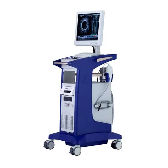
Chapter 2: System Description This chapter describes the main components of the Volcano system, as well as the available options. System Overview The Volcano system consists of the following main components: Monitor Control Console (set in Control Pocket) ... -
Page 21: Monitor
Monitor The 19-inch, high-resolution, flat panel TFT-LCD digital color monitor is provided with the Volcano system. It is a medical grade monitor, and supports 16.7 million colors with a resolution of 1280x1024. The monitor’s color temperature, gamma, brightness, and contrast can be adjusted using the menu located on the lower front of the monitor panel. -
Page 22: Control Console
Control Console Control of the Volcano system is provided through the control console, shown below. Figure 6: Control Console Trackball The trackball moves the cursor on the monitor to allow function selection. The trackball is also used for selecting annotation locations and making measurements. - Page 23 Control Console Key Description Display: Provide enlarged view for printing or reviewing images. Print: Print a 4 x 6 inch (10 x 15 cm) photo of the current image on the screen. Ringdown: Turn Ring Down on or off. Chroma: Turn the ChromaFlo feature on or off.
- Page 24 Control Console Key Description Measure: Initiate autoborder detection. Bookmark: Press while recording a loop to select specific areas of interest for review later. Scroll: Press Scroll once, then move track ball up or down to navigate screen. Press again to disable. Select (+) key: Press to select tabs, areas, or measurement points.
-
Page 25: Joystick Controller Option
The Joystick Controller option for the Volcano system offers convenient sterile field control at the bedside. An available quick-action mount provides easy table mounting and removal. CAUTION: The Volcano system joystick must be installed on the cath lab bedside. Figure 8: Joystick 300004969171/B... - Page 26 Joystick The Joystick controls the movement of the cursor within the graphical user interface. The button on top of the joystick is a Select (+) key and has the same functionality as the Select hardkey on the control console. Selection Keys There are three keys on the joystick: Select (+), Scroll, and Measure.
-
Page 27: Workstation (Central Processing Unit)
Printer A color printer is included with your system to provide high quality color printouts for your patient’s records. Replacement ink cartridges can be ordered through Volcano or most major office supply stores. The printer power switch, located on the printer front panel (see below), is dedicated to ON/OFF function of the printer only. - Page 28 Figure 10: Connector Panel Page 28 of 148 300004969171/B...
- Page 29 Connector Panel Connectors Function Connect Type FM PIM-FFR Push/Pull connection IVUS SA PIM Twist lock SpinVision (PIMr) CORE FM Push/Pull Display Port Push/Pull Push/Pull Network Push and connections latch/unlatch (for DICOM and pull and Image Export) ECG/Aortic Twist lock input connection Connector Push/Pull...
-
Page 30: Patient Interface Module
Do not use the system if the outer case or wires appear damaged. Catheters IVUS imaging catheters are sold separately. Please contact Volcano for more information. The Volcano system is compatible with the following Volcano IVUS catheters: Eagle Eye Gold ... -
Page 31: Available Options
Video Switch: Provides functionality to alternate video input sources to a single monitor Two or Four Channel Video Amplifier: Provides a source for alternate monitor displays Please contact your local Volcano representative for more information on these options. 300004969171/B Page 31 of 148... -
Page 32: Chapter 3: System Setup
You can change these settings at any time by following the instructions in this chapter. Installation To ensure proper operation and warranty coverage, the Volcano system must be installed and tested by following the Device Installation and Operational Qualification that accompanies each device. -
Page 33: Turning System On
Equipotentiality: This symbol on the system rear electrical panel identifies the connector where the hospital room’s potential equalization system can be connected during intracardiac applications. The Isolation Transformer ground in the CORE Mobile system is connected to the ground on the Connector Panel through the CPU by an 8AWG green and yellow striped wire. - Page 34 NOTE: The Volcano system software displays numeric data in a format appropriate for the chosen display language. For example, in English “12.01 mm” in German “12,01 mm”, in French “12,01 mm” etc. (FFR mode additionally displays Regional Settings.) Adjust the date and time. Click the radio button below the Date Format field to ...
- Page 35 Check Compressed ILD On By Default to view the complete pullback in the ILD view. Click OK to save your selections. Click Cancel to disregard selections. Figure 13: Settings – Image Defaults Acquisition Rate Tab The acquisition rate determines how many frames per second are recorded during a pullback and the duration of the video loop at this rate.
- Page 36 Figure 14: Settings – Acquisition Rate Defaults Archive Tab The Archive tab allows you to do the following: Select the information you want included with the frames and video loops when cases are archived: o Measurements o Annotations o Graticules Configure DICOM (See Appendix C for more information) ...
- Page 37 Figure 15: Settings – Archive Defaults VH-IVUS Tab The VH-IVUS tab allows you to do the following: Click VH ON By Default if the VH IVUS images are to be displayed by default when recording video loops, freezing images, and selecting images for review from Case Explorer (only applies to Eagle Eye catheter).
- Page 38 Figure 16: Settings - VH-IVUS Defaults Page 38 of 148 300004969171/B...
- Page 39 Measurement Tab The Measurement tab allows the operator to create and edit measurements and borders. Default Measurement Mode: Select the preferred measurement mode to be active • once a pullback is completed. The measurement options are Diameter*, Draw, or Dots. BorderGuide for Dots: Select whether BorderGuide is turned On or Off*.
- Page 40 Select Mode button and then select Log Off. To log on, enter username and password. Upon installation of v3.3.X Software, a site administrator will be assigned to manage system security. Please contact your site administrator or local Volcano representative if you have any questions regarding enabling the Security feature, adding/deleting users, or lost usernames and/or passwords.
- Page 41 To enable security the administrator must select Enable Security and enter the default username and password. This information should have been provided during installation. If not, please contact your local Volcano Representative. o To disable security, the administrator must select Disable Security and enter the username and password.
- Page 42 o The administrator can also access a report that shows them information on the user and system activity. o To access the report select View Report from the Account Management window. Page 42 of 148 300004969171/B...
- Page 43 This page is intentionally blank for pagination purposes. 300004969171/B Page 43 of 148...
-
Page 44: Chapter 4: Preparing For A Case
The Isolation Transformer ground in the CORE Mobile system is connected to the ground on the Connector Panel through the CPU by an 8AWG green and yellow striped wire. (Equipotentiality cords are available from Volcano Service: PN 804768001 singled ended, PN 804769001 double ended.) -
Page 45: Connect The Pim
NOTE 1: Leave the power on during the case unless there is an emergency. NOTE 2: If the Volcano logo indicator is not lit, make sure that the system power is on and plugged into a hospital grade grounded outlet. Make sure the fuse switch is turned on (I symbol). -
Page 46: Enter Patient Information
NOTE: Imaging will not start until the catheter is connected to the PIM. Connect the ECG Input ECG input must be connected to the Volcano system in order to provide VH analysis (for Eagle Eye catheter). VH IVUS is only available for review if a valid ECG signal was received during acquisition. - Page 47 Figure 19: Patient Information Dialog Box NOTE: The Select Mode button is only available on Volcano system version 3.3 or higher: 400-0100.01, 400-0100.07, and 400-0100.08. Enter or edit the patient information using the keyboard, or, if the DICOM network worklist is configured in Settings, select the patient from the worklist.
-
Page 48: Chapter 5: Acquiring Ivus Images
Insert the Catheter The Volcano imaging catheters are designed for placement using standard intra-operative or percutaneous techniques by suitably trained physicians. The frequency and duration of administration is subject to the discretion of the physician and depends upon the procedure and information required. -
Page 49: Adjust The Image (If Desired)
Figure 20: Home Tab Showing Live Imaging Adjust the Image (if desired) Your system’s image settings will be set to the default values recommended by the manufacturer. These settings can be adjusted based on your preferences. Once set, specific values persist until changed. To change the settings, press the Adjust Image button. - Page 50 Figure 21: Adjust Live Image Dialog Box NOTE: The TGC button requires installation of the Revo Option on Volcano system version 3.3 or higher: 400-0100.01, 400-0100.07, and 400-0100.08. Turning VH IVUS Display On/Off VH IVUS offers automatic border detection and tissue classification. This feature is available for the Eagle Eye catheter family.
- Page 51 Adaptive NearVu adaptively corrects for acoustic interference in the image region around the IVUS catheter. It is the default setting for all Eagle Eye Catheters. NOTE: The operator should ensure there is no tissue or artifact present from guide catheter in the ringdown area before turning on NearVu. Otherwise, a persistent image artifact can remain in the ringdown area.
- Page 52 3 Hold the Select(+) key down to rotate the image continuously. 4 To rotate the image in a counterclockwise direction, select the bottom box with the red and blue rotational arrows and follow the same steps as above. Setting Gain Gain refers to the intensity of the ultrasound echoes.
- Page 53 Setting Diameter Diameter is the depth of the field of view to which the ultrasound image data is acquired. The following table defines range of diameter and increments for each catheter. Catheter Type Diameter Range Diameter Step Changes Eagle Eye Gold 8-20 mm Eagle Eye Platinum 8-20 mm...
-
Page 54: Chapter 6: Recording Ivus Images
Chapter 6: Recording IVUS Images This chapter describes the methods of recording images. Please refer to the previous chapter for information on inserting the catheter and adjusting the image settings. Overview Images can be recorded by either saving a single frame (Save Frame) or recording a video loop of multiple frames. - Page 55 When in LIVE mode, press Record on the control console or the green Record Loop button to record multiple frames of ultrasound image during a pullback. Capture up to 10 video loops, each with up to 5400 frames. The In-Line Digital (ILD) software display shows a sagittal view of the blood vessel to the right of the tomographic view during the recording.
-
Page 56: Saving A Frame
Figure 25: Recording a Video Loop Saving a Frame The Volcano system can store up to 99 frame images from a live view or a video loop. Saved frames are labeled automatically and numbered F1, F2, F3, etc. To save a frame: 1 Press the Save Frame button on the control console or on the Home screen in live mode. -
Page 57: Chapter 7: Reviewing Ivus Images
Chapter 7: Reviewing IVUS Images This chapter describes the process for reviewing IVUS images as well as the tools available for analysis. Overview The Case Explorer provides a list of all the video loops and saved frames for the open case. -
Page 58: Reviewing Saved Frames
Displaying Images To view an image listed in the Case Explorer, move the cursor over the desired image and press the Select(+) key on the control console. Image Options Menu Various options associated with images may be accessed by pressing the Menu(-) button while the cursor is positioned over the item of interest in the Case Explorer list. - Page 59 Play and Stop Controls to play and stop the video loop are located on the control console and in the lower right hand section of the screen under the ILD. Figure 27: Review Toolbar, Play When the video loop is playing, a white frame marker moves downward to represent movement through the frames captured when the loop was recorded.
- Page 60 Creating/Reviewing Bookmarks Bookmarks can be created during playback of a video loop by pressing the Bookmark button on the control console or software while the loop is playing. A bookmark will be created for the frame that is currently displayed at the time that the button is pressed. Bookmarks can be selected for review using the Case Explorer or by using the Bookmark up/down arrows located at the bottom of the ILD.
- Page 61 In-Line Digital (ILD) Display The In-Line Digital (ILD) displays a sagittal view of the blood vessel that offers additional information for lesion diagnosis, longitudinal measurements, and other diagnostic and treatment options. Beginning of Segment of Interest Current frame marker Scroll bar End of Segment of Interest Play/Stop buttons...
- Page 62 Navigating the ILD There are three ways to scroll through frames in the ILD: Click on the tag of the white marker line and then scroll through video loop. Click once more to release the cursor line. Alternatively, you can click on the up/down arrows on the tag to move one frame at a time.
- Page 63 Figure 32: ILD Display of Tomographic View To rotate the vessel: 1 Mouse over the arrow at the center of the tomographic image until a horizontal blue line spans the image and a half circle with arrows appear in the center. 2 Press the Select key (+) to rotate the arrow in the counterclockwise direction;...
-
Page 64: Display Mode
Figure 34: Rotated ILD Display Display Mode The display mode can be changed to display a larger tomographic view. Select the display button on the control console to increase or decrease the size of the tomographic view. This view provides another option for printing an image as a report. The ILD and navigation buttons are not displayed in this view. - Page 65 NOTE 1: An approximate five-second delay occurs between pressing the Print button and printer activation. NOTE 2: Replacement paper and ink cartridge kits can be ordered through Volcano Corporation or at your local office supply store. 300004969171/B Page 65 of 148...
- Page 66 This page is intentionally blank for pagination purposes. Page 66 of 148 300004969171/B...
-
Page 67: Chapter 8: Making Measurements And Annotations
Chapter 8: Making Measurements and Annotations This chapter describes the measurement and annotation tools that are available on your system. The measurement tools do not apply to VH frames. See the next chapter for VH measurements. NOTE: Measurement accuracy is dependent on operator’s familiarity with specified measurements and interpretion of ultrasound images. - Page 68 3 Move the cursor to where you want to end the measurement and press Select (+) to anchor it. The diameter line is drawn in color with the number 1 displaying on each end. 4 Repeat for up to 4 diameter lines. Each line will be in a unique color. The diameter measurement, in millimeters (mm), is displayed by number and color at the top left corner of the image.
- Page 69 2. For manual border generation, select either the Draw or Dots button in the Home Tab screen i. Draw: Press Select(+) and use the cursor to trace the border. When you have finished, press Select(+) to release the border and click on the Done button or double click Select(+) button.
- Page 70 Figure 36: Measuring Vessel Area To edit the area measurement: 1 Position the cursor over a border and press Select(+). The border becomes a dashed line. 2 There are two ways to edit: i. In Draw edit mode the user can click on the area measurement line and begin to draw the border contour.
- Page 71 Figure 37: Editing the Vessel Area To delete area measurement: 1 Select the Delete button in the measurement toolbar. 2 Using the trackball, move the scissors to the area measurement. When the line is highlighted, press Select(+). NOTE: There is no “undo” for deleting an area measurement. Measuring Vessel Length NOTE: Measure vessel length in the ILD only if a non-manual pullback rate has been selected.
- Page 72 Figure 38: Measuring Vessel Length To measure the vessel length: 1 Click the Diameter button. 2 Using the trackball, move the cursor into the ILD and press Select(+) to anchor the first point. 3 Move the cursor to the desired end point and press Select(+)again to anchor the line at the second point.
- Page 73 Annotating Frames Using the keyboard, you can annotate saved frames and video loops. 1 Select a saved image or video loop to annotate by clicking on its name in the Case Explorer. 2 Using the trackball on the control console, move your cursor to the image area you wish to annotate.
- Page 74 Measuring Percent Difference This feature provides the ability to compare differences in areas between two grayscale frames. For example, you can compare the percent difference between the minimum lumen area on one frame to a reference lumen area on another frame.. The following formula is used to calculate percent difference: % Difference = 1 –...
- Page 75 Figure 41: Draw measurement on 2nd frame of interest To edit a percent difference measurement: o Move the cursor over the area measurement then press Select(+) once it is highlighted. o Edit as needed. o Click on the lock icon again to lock in the new measurement. o The percent difference calculation will now be updated.
-
Page 76: Chapter 9: Using Vh Ivus
IVUS is not gated. As a pullback occurs, the VH borders are identified on the ILD. NOTE: A valid ECG signal must be received by the Volcano system during acquisition for VH to be available. Page 76 of 148... -
Page 77: Activating Vh Display
Activating VH Display Select the VH button on the control console to enable or disable VH display feature. The default setting is VH off. Figure 42: Control Console 300004969171/B Page 77 of 148... -
Page 78: Using The Vh Screen
Using the VH Screen Figure 43: VH Display The following tasks can be accomplished using the main screen: Click the Pie chart to display the tissue composition statistics on the screen Click the Visibility box to display the borders and/or VH IVUS ... - Page 79 Figure 44: Border Edit Mode – Tomographic View Border Edit Mode The borders can be edited by performing any of the following in the tomographic or ILD view: Tomographic View: 1 Position the cursor over a border and press Select(+). The border becomes a dashed line.
- Page 80 NOTE: It is recommended to consult with your local Volcano representative prior to using this feature. This mode can be activated in Settings under the VH-IVUS tab. Please note that this mode must be selected prior to acquisition.
-
Page 81: Using Target Assist
Using Target Assist The Target Assist feature will automatically locate and identify the minimum lumen area (MLA) within the active video loop. To utilize this feature: 1 Adjust the proximal and distal reference lines to define the region of interest. Make sure to exclude the guide catheter. -
Page 82: Chapter 10: Using The Chromaflo Feature
This is possible by utilizing ultra high speed electronics and Volcano’s proprietary algorithms. NOTE 1: Available on Eagle Eye family of catheters, Pioneer Plus, and Visions PV .014P and .018 catheters. -
Page 83: Controlling The Sensitivity
Figure 48: ChromaFlo Image Controlling the Sensitivity The Sensitivity setting controls the system’s ability to detect and image blood flow color representation in the artery. Areas where the blood is moving faster are more yellow: areas where the blood moves more slowly are red. The sensitivity can be increased to intensify the color of slower moving areas of blood flow, or it can be decreased to diminish the color of faster moving areas of blood flow. -
Page 84: Deactivating The Chromaflo Feature
Each increment changes the diameter by approximately 0.52 mm with a tolerance of ± 0.03 mm. Deactivating the ChromaFlo Feature To deactivate the ChromaFlo feature, press the Chroma key on the control console, or open the Adjust Image dialog box and uncheck the ChromaFlo On check box. Page 84 of 148 300004969171/B... - Page 85 This page is intentionally blank for pagination purposes. 300004969171/B Page 85 of 148...
-
Page 86: Chapter 11: Ending An Ivus Case
Chapter 11: Ending an IVUS Case Overview An open case exists after the patient information and/or image data is collected. Once the case is complete, you must end the case before starting a new one. Ending a case is equivalent to saving the case to the system’s hard drive. Alternatively, you may choose to delete the case. -
Page 87: Deleting A Case
2 Verify that the patient data is correct or perform edits as needed. 3 Click OK when you are ready to end this case. The case is saved to the hard drive and appears in the list box with Case Type Original. NOTE 1: All the cases on the hard drive appear in the list box. -
Page 88: Chapter 12: Archiving An Ivus Case
Chapter 12: Archiving an IVUS Case Overview A maximum of 20 patient cases can be stored on the system’s hard drive. Saving to a hard drive is faster than saving to to a DVD. However, archiving a case to a DVD allows for viewing or exporting of images or video loops on other PCs. - Page 89 NOTE: The archived images are stored in DICOM format with Volcano system acting as a File Set Creator (FSC), following the guidelines in the 2004 DICOM 3.0 specification.
-
Page 90: Archiving Using Dicom
To prevent the potential loss of data, always use a new DVD-R when archiving patient cases to the DVD-R. Do not share DVD-Rs from other non Volcano systems or computers with the Volcano system; instead keep a separate supply of DVD-Rs just for the system. - Page 91 This page is intentionally blank for pagination purposes. 300004969171/B Page 91 of 148...
-
Page 92: Chapter 13: Switching Modes
Chapter 13: Switching Modes Overview This chapter describes how to switch between available modalities. Entering Patient Information If planning to use more than one mode for a single patient, enter the patient information in the IVUS modality before switching modes. Switching Modes You can switch from one modality to another by clicking on the Select Mode button shown below. - Page 93 This page is intentionally blank for pagination purposes. 300004969171/B Page 93 of 148...
-
Page 94: Chapter 14: Retrieving And Deleting An Ivus Case
Chapter 14: Retrieving and Deleting an IVUS Case Overview This chapter provides the instructions for retrieving a case that has previously been ended to review and/or edit case data. Cases can be retrieved from: System Hard Drive NOTE: Cases cannot be retrieved from the DICOM Network. In addition, instructions are provided for deleting an IVUS case from the hard drive. -
Page 95: Deleting A Case
Move the cursor over the desired case and press Select (+) to select it. The case is highlighted. Press the Start Retrieve button to transfer the data from storage to the Volcano system. A bar on the screen indicates the progress of the data retrieval. NOTE: You can retrieve only one case at a time. -
Page 96: Removing Power From System
Removing Power from System 1 Turn off system power. 2 Unplug the system at the appliance power inlet (wall socket). 3 Do not block accessibility to the appliance power inlet. Page 96 of 148 300004969171/B... -
Page 97: Chapter 15: Image Export Option
Please reference instructions for use in the IVUSMap section of the Siemens manual. When this feature is enabled on the Volcano system, registered IVUS images are sent to the Siemens system automatically after acquisition. Two unique behaviors occur on the Volcano system when the Image Export feature is enabled: 1. - Page 98 If Image Export is enabled and an active connection is available between the Artis and Volcano system, the right bottom corner of the Status Bar shows “Image Export: ON”.
-
Page 99: Chapter 16: Troubleshooting
Chapter 16: Troubleshooting Message Alerts Message Reason Resolution Press F1 to continue Upon startup the BIOS battery is failing. Contact your service representative to replace the BIOS battery. Note: Until battery is replaced, current day/date will need to be manually reset each instance of power on. - Page 100 When cards fail, down. The power Checker module. Please this message appears. disconnected from the system contact Volcano for 10 seconds. Then start up Technical Support to fix system. If startup fails again, the problem. Click call Technical Support.
- Page 101 Technical Support. There was a problem synchronizing the Reboot the system and try Error creating a new patient case. Volcano system patient data with GE’s again. If problem persists, call Innova system. Technical Support. Error saving patient case There is a problem with the hard drive.
- Page 102 Unknown Archive Dialog There is a problem with archiving software Try archiving with another Message or DVD or DVD drive. DVD, if that does not work, save the patient case, reboot the system and try archiving again. If problem persists, call Technical Support.
- Page 103 The DICOM file on the DVD could not be Try cleaning the DVD. Ensure file read most likely due to dirty/damaged DVD the archived case is a Volcano- system case. Unable to open config file The system cannot archive this case.
-
Page 104: Potential Imaging Artifacts
Technical Support. Potential Imaging Artifacts The Volcano system software is designed to minimize artifacts and errors. As with any imaging modality, however, some artifacts may occur. Images or features may be presented on the screen which do not directly represent a physical structure or which may cause image defects. - Page 105 artifacts may persist for a sustained period in following images. If imaging catheter has been placed next to a relatively stationary and bright tissue (e.g. calcified plaque), moving the catheter away afterward may create an artifact that may remain on screen for a short time.
- Page 106 Reduced Due to processing speeds in ChromaFlo mode, the None. Very fast overall frame rate of the Volcano system is lowered moving structures frame rate to approximately 12 frames per second, which may appear to move represents combined grayscale and color features.
- Page 107 signals are usually lower than tissue features. However, slow-moving (<1 cm/sec) acoustically soft tissues, such as plaque and lipids, can give rise to low level signals of the same order as faster moving blood (>4 cm/sec). In these cases, the tissue will be coded as color.
- Page 108 Potential Imaging Artifacts - In-Line Digital (ILD) NOTE 1: Length measurements are not representative of anatomy, since the computer display will always represent the catheter pullback as a linear translation. NOTE 2: Due to potentially significant inaccuracies, the user should carefully review any computer generated boundary before proceeding with a measurement.
-
Page 109: Eu Battery Directive, 2006/66/Ec Requirements
EU Battery Directive, 2006/66/EC Requirements Instructions for battery removal for disposal when decommissioning the unit: 1. Power down the workstation and unplug the unit. 2. Open the workstation side panel to access the interior of the unit. 3. Remove the coin battery from the motherboard of the workstation. 4. - Page 110 This page is intentionally blank for pagination purposes. Page 110 of 148 300004969171/B...
-
Page 111: Chapter 17: Maintenance
The Volcano system contains no user-serviceable components. To avoid electrical shock, do not remove any panels or covers. In the event of malfunction or system damage, turn the system off, unplug the system from the power receptacle, and contact a Volcano- certified service person and/or Volcano Technical Support. -
Page 112: User-Performed Maintenance
Volcano-Certified Maintenance Volcano-certified maintenance is performed by Volcano-certified service engineers only. A comprehensive preventive maintenance procedure needs to be done annually, starting approximately 18 months post-installation. User-Performed Maintenance Archive Patient Cases See Archiving an IVUS Case chapter. Cleaning and Disinfecting the Volcano System Clean and disinfect the system, patient interface module, and other parts of the ... - Page 113 of the product. The plastic is composed of acrylonitrile, butadiene, and styrene (ABS). Consult cleanser manufacturer to see if agent is compatible with ABS. CAUTION: Never spray or otherwise apply any cleaner directly to the touch screen because leakage could cause damage to the system. Always apply the cleaner to the cloth instead.
- Page 114 4. Wash the filters with a mild detergent solution, and allow them to dry thoroughly. 5. If there is dirt accumulated on the front fans, clean with a vacuum. 6. Replace fan covers by aligning the cover holes with case pins, and press covers onto case pins.
-
Page 115: Volcano-Certified Maintenance
Inspect cable connections to ensure secure connections Volcano-Certified Maintenance Volcano-certified maintenance is performed by Volcano-certified service engineers only. A comprehensive inspection, operational check, entire system test, and check of any installed options are required. 300004969171/B Page 115 of 148... - Page 116 This page is intentionally blank for pagination purposes. Page 116 of 148 300004969171/B...
-
Page 117: Chapter 18: Technical Specifications
NOTE 1: Additional information is available in the “Physicians Guide and Instructions for Use” that accompanies each catheter. NOTE 2: Information about the technical specification for the Revolution catheter, refer to the Volcano System Revo Option Operator’s Manual. Video System Video Display Format Display port and DVI/HDMI/VGA adaptors are available ... - Page 118 Image Live/Still modes Variable frame rate 360° image Multiple depth scaling Image Sizes Image Mode Image Area (in pixels) Max IVUS 750 x 750 Normal Imaging Mode 500 x 500 Page 118 of 148 300004969171/B...
-
Page 119: Core Mobile Dimensions And Weights
CORE Mobile Dimensions and Weights Volcano System Height, in Width, in Depth, in Weight, lb CORE Mobile ~210 Cart Height, cm Width, cm Depth, cm Weight, kg CORE Mobile 157.48 55.88 83.82 ~95.25 Cart Power Volcano Ratings and Fusing System Input... - Page 120 Power Specifications—Input Maximum Continuous 550 watts Power Hold-up Time >40ms @ full load Over voltage Protection +15% of set voltage Overload Protection Auto Recover Minimum Loading None Cross regulation <0.5% Line & Load regulation <0.5% Turn on Time < 2 sec EMC Compliance Compliance to the following standards: EN61000-4-2 ESD level3...
-
Page 121: Recording Devices
other device(s) are connected. Consult the manufacturer or Technical Support technician for help. Do not attempt to replace any cables or accessories with non-Volcano approved components as this may affect EMC performance. 300004969171/B Page 121 of 148... -
Page 122: Electrical Safety
DICOM Image Storage Saving patient cases to DVD: The archived images are stored in DICOM format with the Volcano system acting as a File Set Creator (FSC), following the guidelines in the 2004 DICOM 3.0 specification. The DICOM images will be stored using the Ultrasound Application Profile STD-US- SC-MF-DVD, using the UIDs in the following table. -
Page 123: Essential Performance, Catheter Operating Temperatures
The catheters are designed to image under physiologic conditions. Operating Temperature of all solid-state array catheters used with the Volcano system is <55 +/- 0.3 °C in air and <41+/- 0.3 °C under physiologic conditions (37 °C in fluids). Operating Temperature of rotational catheters used with the Volcano system is 1 +/- 0.3 °C above ambient... -
Page 124: Catheter Acoustic Outputs
Ultrasound exposure only when LIVE imaging is enabled. When LIVE imaging is not selected by the operator, no ultrasound exposure occurs. The Volcano system is in compliance with the Acoustic Output Display Standard and are within FDA limits for Ultrasound equipment. - Page 125 Eagle Eye Platinum Acoustic Output Parameter B-Mode ChromaFlo (mW/cm 2.93x10 7.98x10 SPTA (W/cm 7.5x10 175.0x10 SPPA (MPa) 20.0x10 81.5x10 PD (µs) 161.0x10 125.0x10 PRF (Hz) 53760 75368 Center Freq (MHz) 18.6 17.9 4.5x10 1.92x10 2.06x10 1.56x10 1. Uncertainty: +/- 24.5% 2.
- Page 126 Uncertainty: +/-12.3% PV .018 Acoustic Output Parameter B-Mode ChromaFlo (mW/cm 2.087 13.950 SPTA (W/cm 0.2963 1.709 SPPA (MPa) 132.3x10 267.7x10 PD (µs) 168.3x10 113.8x10 PRF (Hz) 43008 70656 Center Freq (MHz) 3.055x10 5.306x10 2.698x10 4.748x10 1. Uncertainty: +33.9% / -30.5% 2.
-
Page 127: Measurement Accuracy
PRF: Pulse Repetition Frequency (Hz) Measurement Accuracy Measurements obtained with the Volcano system are subject to the following measurement inaccuracies due to variations in tissue speed of sound and display limitations. The measurement precision is limited in both relative and absolute ranges: Distance Measurement: –4.5%, +7.0% of measured value ±... -
Page 128: Accessories And Replacement Parts
Accuracy (Trak Back, R-100 Pull Back ± 5%) @ 30 fps & 1.0 mm/sec pull back -> 90 mm Accuracy (Trak Back, R-100 Pull Back ± 3%) Accessories and Replacement Parts NOTE: The Volcano system is compliant to IEC 60601-1-2 with the following accessories and cabling. Volcano CORE System Maximum Description Part Number... -
Page 129: Standards And Regulations
IEC 60601-2-34:2011 CAN/CSA C22.2 No. 60601-1-14 The Volcano system FFR Option does not comply with Clause 51.102.1 since the guide wire’s pressure transducer can drift over extended periods of time. It is important that the guide wire’s reading be verified every 10 minutes and normalized to the aortic reading if drift has occurred. - Page 130 Guidance and Manufacturer’s declaration – electromagnetic emissions Volcano System Series The Volcano System Series of systems is intended for use in the electromagnetic environment specified below. The customer or the user of the Volcano System Series should assure that it is used in such an environment. Emissions Test...
- Page 131 Series The Volcano System Series is intended for use in the electromagnetic environment specified below. The customer or the user of the Volcano System Series should assure that it is used in such an environment. During immunity testing the Volcano system was exercised by placing the system in a simulated imaging mode with normal operation indicated by an active image portrayed on the display.
- Page 132 If the measured field strength in the location in which the Volcano System Family is used exceeds the applicable RF compliance level above, the Volcano System Family should be observed to verify normal operation. If abnormal performance is observed, additional measures may be necessary, such as re-orienting or relocating the Volcano System Family.
- Page 133 Guidance and manufacturer’s declaration – electromagnetic immunity The Volcano System Family Image Intensifier is intended for use in the electromagnetic environment specified below. The customer or the user of the Volcano System Family should assure that it is used in such an environment.
- Page 134 70% U ; 25/30 70% U ; 25/30 recommended that the Cycles Cycles Volcano System Family be powered from an Single Phase: at Single Phase: at uninterruptible power supply or a battery. 0% U ; 250/300 0% U ;...
-
Page 135: Symbols
Symbols This chapter lists symbols used on the Volcano system and their meanings. Complies with the Council Directive 93/42/EEC Power Off Power On Warning, Attention, Consult Accompanying Documents Power On/Off Laser Warning, Attention, Consult Accompaying Documents Patient Interface Module (PIM) Connector... - Page 136 Attention: observe precautions for handling electrostatic discharge sensitive devices. Recycle Humidity Limitation Atmospheric Pressure Limitation Temperature Limitation Follow Operating Instructions Follow User Manual Consult Instructions for Use Volcano Corporation Logo Manufacturer Date of Manufacture Page 136 of 148 300004969171/B...
-
Page 137: Glossary
Sensitivity: During ChromaFlo imaging, blood/ luminal flow rates can vary from 4 cm/sec up to 110 cm/sec. The Volcano system is equipped to display, in color, 5 viewable flow ranges. This capability is accessed via the Sensitivity control which is available on the Adjust Image menu. -
Page 138: Appendix A: Vh Measurements
Appendix A: VH Measurements This appendix defines the statistics available using VH IVUS. Frame Results Lumen area: cross-sectional area of the lumen for this frame. Vessel area: cross-sectional area of the vessel for this frame. Plaque area: cross-sectional area of the plaque for this frame. # plaque plus (+) media complex = plaque area # Vessel minus (-) the lumen area = plaque area % Plaque Burden: Plaque Area divided by Vessel area. - Page 139 Lumen dia max: largest diameter measurement within the defined segment. This measurement occurs at the frame number displayed. Min Lumen Area: smallest lumen area within the defined segment. This measurement occurs at the frame number displayed. Vessel dia min: smallest diameter measurement within the defined segment. This measurement occurs at the frame number displayed.
-
Page 140: Appendix B: Technology Summary
Appendix B: Technology Summary The development and validation of VH IVUS on the Volcano system platform is outlined below. Methods The human left anterior descending (LAD) coronary artery was obtained at autopsy. IVUS data from 63 LAD specimens were analyzed with IRB approval from the Cleveland Clinic Foundation, Cleveland, Ohio. -
Page 141: Accuracy Analysis
93 lesion sections. See Table 1 for the corresponding distribution of the ROIs by tissue type. Table 1. The number of regions-of-interest (ROIs) of each tissue type that were used for training the Volcano system Eagle Eye VH algorithm. Tissue Type Number of Training ROIs... -
Page 142: Results
Results Table 3 summarizes the sensitivity, specificity, and predictive accuracy results. Table 3. The predictive accuracy, sensitivity, and specificity of the Volcano system Eagle Eye VH classification tree by tissue type. Number of Predictive Tissue Type Evaluation Sensitivity (%) Specificity (%) -
Page 143: Appendix C: Configuring Dicom
Local Host–Network Settings Host Name: The factory host name default is “CORE.” This field configures the computer host name for the Volcano system. IP Address: This field is used to configure the network Internet Protocol (IP) address for the system. - Page 144 Subnet Mask: The Volcano systems use the Subnet mask to determine if communication with the remote host needs to be routed through a gateway. If so, this field configures the Subnet mask for the system’s subnetwork. Gateway: This field is used to configure the gateway IP address for the system.
- Page 145 Volcano system. This drop down contains the list of configured servers. The currently selected server will be used for subsequent configuration changes and will also be the server that receives DICOM images from the Volcano system during an Archive to Network operation.
- Page 146 AE Title: This field is used to configure the Application Entity Title field of the remote DICOM Store SCP (Service Class Provider) application to which the Volcano system will be sending images. The factory default is “STORE_SCP”. Port Number: This field is used to configure the port number to which the ...
-
Page 147: Worklist Servers Configuration
JPEG High Quality o JPEG Medium Quality o JPEG High Compression Check Button: This button is used to test the connection between the Volcano DICOM SCU and the remote DICOM Storage SCP. The connection is tested using the DICOM C-ECHO service (Verification class). - Page 148 Worklist Server - Network Settings The following network parameters are configurable for the each defined Remote DICOM Storage SCP Server Host name: Computer Host name of the remote device. IP Address: IP Address of the remote device. Find: Performs a network PING to determine in the configured device is ...
Need help?
Do you have a question about the CORE Mobile and is the answer not in the manual?
Questions and answers