Table of Contents
Advertisement
Quick Links
Advertisement
Table of Contents

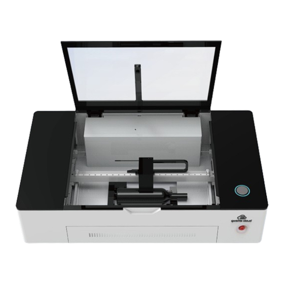
Summary of Contents for gweike cloud Desktop 3D Laser Printer
- Page 2 FOREWORD Thank you for choosing to use the Gweikecloud laser cutting machine produced Spc Laser Co ltd. We will provide you with comprehensive after-sales service and solutions. Please keep this manual and other accessories in good condition so that you can use this product better.
-
Page 3: Table Of Contents
CONTENTS Introduction Ⅰ. Safety 1.Laser Safety 2.Electrical Safety 3.Fire Safety Ⅱ. Certi cation/ Identi cation/Warning Labels Do and Don’t Getting Started Getting Acquainted Ⅲ. Unboxing & Setting Up 1.Unboxing 2.Machine installation Ⅳ. Operation 1.Login in 2.Turn on and connect to the WI-FI 3.How To Print Your First Work Ⅴ. - Page 4 CONTENTS 4.Clean The Camera 5.Clean the protective lens Ⅷ.Problem And Resolve 1.How to adjust the focus? 2.Flame problem 3.If the machine is working abnormally, what should be checked? 4.Wifi Can't Connect 5.The Color Of The Indicator Light 6. When the image taken by the camera has a large deviation from the actual cutting image (the deviation within 2mm is normal) 7.If the cutting material is larger than the machine format, how to realize the front and back feeding...
-
Page 5: Introduction
INTRODUCTION How to Use This Owner’s Manual T hank you for purchasing an GweikeCloud Laser system. Your GweikeCloud system has been designed to be easy to operate, but you will utilize it to its fullest potential by taking some time to read this owner’s manual prior to use. You will be ready to use the GweikeCloud Laser system as soon as you read the first few sections. -
Page 6: Laser Safety
DO NOT disassemble the machine or remove any of its protective covers while the unit is plugged in. DO NOT attempt to defeat the door interlocks. DO NOT view directly into the beam of the Laser Diode Pointer (Red Dot Pointer). DO NOT operate the Laser Diode Pointer (Red Dot Pointer) without the machine’s focus lens in place. -
Page 7: Fire Safety
3. Fire Safety The gweikecloud unit’s laser cuts and engraves with a beam of high-intensity infrared light. The laser can generate extremely high temperatures in the material being cut or engraved. Under some circumstances, it is possible for the material inside the gweikecloud unit to ignite and for the flame to spread outside of the area being cut or engraved. - Page 8 Removable interlock protection safety label: There is a label on the back of each cabinet of the machine; One at the front, one at the top. One on the left and one on the right. Laser radiation warning label: this label is located at the back right side of the machine Laser Aperture Label: This label is located on the laser head...
- Page 9 This label is located on the place to open the doorwhere the dooropens. Power Labels: The appropriate label for the machine is located on or below the power module panel at the right side of the machine’s cabinet. Aperture Safety Label: This label is located above the aperture, inside the cabinet, where laser beams enter the machine’s engraving Area, one on...
-
Page 10: Do And Don't
NOTE: This equipment has been tested and found to comply with the limits for a Class A digital device, pursuant to Part 15 of the FCC Rules.These limits are designed to provide reasonable protection against harmful interference when the equipment is operated in a commercial environment. -
Page 11: Getting Started
a small amount of effort at the end of the week will pay off with years of trouble-free operation of your machine. See the section “SYSTEM MAINTENANCE” on page for specifics. Getting Started Follow these steps to set up your Laser system: 1. -
Page 12: Ⅲ. Unboxing & Setting Up
Thank you for your patience. Now, it’s time to get lasering!Let’s get started, shall we? Laser Printer & Accessory Pack You will receive two packages. Package 1 includes GWEIKE Cloud laser printer, material package and accessories. Package 2 includes air filter. Duct adapter... -
Page 13: Unboxing
*The box is specially designed to protect your gweikecloud through all shipments, domestic and international. Be sure to keep the box and packing materials, as you'll need them if you want to transport your gweikecloud again or for any warranty repair. 1.Unboxing (1).Using handy tools to open and remove the carton cover. - Page 14 (2).Take out the wrapped "honeycomb board"and the sponge on the top of the box. (3).Choose a table with a hard, flat and stable surface. If the desktop is unstable, uneven or too small, it may cause deviations of printing accuracy and may even damage the laser printer.
- Page 15 (4).Take the 3D laser printer out of the wooden box. Remove the orange belt and the plastic bay belt . Place it on the prepared desktop.Open the cover of the machine and take out the accessories inside the machine.
-
Page 16: Machine Installation
2.Machine installation (1).Pull out the waste scrap tray, put the honeycomb board into the bottom of the laser printer, and then reinstall the waste scrap tray. - Page 17 Don’t put in honey comb plate from top side. (2). Duct Fan Installation Manual Before : Preparation: Fan, Screwdriver, 120mm air hose *1, 150mm air hose*1, 120-150 reducer*1...
- Page 18 (1).Connect the 120-150 reducer to the air inlet of the fan. (2). Unfold and stretch the retractable aluminum air hose. (3). Connect one end of the 120mm air hose to the exhaust port of the machine, and the othver end to the air inlet of the fan, and tighten the clamp with a screwdriver.
- Page 19 (4). Connect one end of the 150mm air hose to the exhaust port of the fan, and tighten the clamp with a screwdriver. (5). Place the connected fan on the window sill with the air outlet facing outwards. (6). Plug the power cord to finish the installation.
-
Page 20: Ⅳ. Operation
(7). Upload the drawing and start cutting. Check if any smoke and dust leaks from the front, side and top of the machine. (8).The flue smoke exhaust effect will be stable after the increase of cutting time, then no smoke and dust will be discharged around the machine body. Ⅳ. - Page 21 (2).Click "Cloud" in the website (refer to Google Chrome) Click the "Create one now". Register an operating account on the cloud (3). laser Website.Note: If account already registered when make payment, please use it and please don't register again. Note: If account already registered when make payment, please use it and please don't register again.
- Page 23 After register your account successfully,click the to https://www.gweikecloud.com/cloud, Login in your account, Enter your account and password. (5) Input your machine ID, the machine ID is on the lable on the back of the machine. When shows “GWEIKE CLOUD added successfully”, pls click “Next”.
-
Page 24: Turn On And Connect To The Wi-Fi
2.Turn on and connect to the WI-FI (1) "I", Turn off is "O"), and you'll see the button green to dark, which means the machine has finished resetting. Confirm The Wifi Environment Machine and WiFi, distance must be within 3 meters, and no wall between them.t... - Page 25 Wifi should be 2.4GHz, 5G not. If the network is unstable, please add a WIFI singal booster. (3) Press and hold the button on the device for 5 seconds, The color of the button will change from purple to red, back and forth. And then click “Next”.
- Page 26 Notice:If you cannot find the WIFI starting with "device" or "gweike", please turn off the computer or laptop WIFI, and then turn on the computer or laptop WIFI again, repeat several times. When the device WIFI display is connected, the device WIFI connection is successful.And then click “NEXT”.
- Page 27 Select country directly NoticeⅠ.Connect successfully does not represent that the WIFI connect successfully , and the off of button light of the machine automatically indicates that the WIFI connection is successful. Ⅱ.If you accidentally exit, please click https://www.gweikecloud.com/cloud, choose a design and clickprint,you will enter processing interface, click WIFI,then click "WIFI Configuration".
- Page 28 (7).Upload files Enter the customer center, upload the file (supported file formats support JPG, PNG, SVG).Remarks: Click the Device to switch Device. Move the mouse cursor to a file, click Print to jump to the operation page.
- Page 29 And the device status on the operation page displays "Ready" or "reset", it proves that the wifi connection is successful. it means that the WIFI connection is successful. (8). The WIFI is successfully connected to the network, please click the "Select" button on the operation page to select the processing material (the Print button is grey and cannot be clicked if the material is not selected).
-
Page 30: How To Print Your First Work
3.How To Print Your First Work (1).Open the cover of your gweikecloud, choose a piece of material with an area less than 540mm*310mm and place it on the honeycomb panel of the machine. Make sure that the QR code is clearly visible on the material and close the cover completely. (2).After closing the machine cover, the machine resets, the camera automatically takes pictures and uploads the machine processing table image. - Page 31 Remarks: gweikecloud official materials, with barcode, the device can automatically Remarks: gweikecloud official materials, with barcode, the device can automatically identify, automatically select parameters, no need to manually set. Non-gweikekecloud identify, automatically select parameters, no need to manually set. Non-gweikekecloud material Please manually click the "Select"...
- Page 32 (4).Select the part that needs to be processed, Shift+left mouse button, and drag the fixed point to zoom the selected file proportionally; move the mouse to the canvas range, ctrl+mouse wheel to zoom in and out of the canvas. Drag the image with the mouse to move it to a suitable processing position.
- Page 33 (7).In the operation interface of your computer, you will see the processing time. (8).After the processing is over, take out the processed finished product. Note: During The machining process, someone must observe the machining situation to avoid machining errors. (9).Take out the cut parts from the machine and splice them together. Congratulations, you have completed your first work.
- Page 34 figure 3 (10).Suspend processing If you need to suspend processing during processing, you only need to press the equipment button, and the laser printer will suspend processing. (If you open the top cover of the laser printer during processing, the LED lights in the laser printer will dim, and the laser printer will also suspend processing).
-
Page 35: Ⅴ. Other Functions Introduction
Ⅴ. Other Functions Introduction 1.Function of extraction ①.Open the cover of the machine, put the hand-drawn drawings or other objects with patterns on the surface of the machine table, and close the cover. ②.After the machine cover is closed, the machine will reset, then the camera will automatically take pictures, and wait for the image to refresh to the operation interface or click Preview. -
Page 36: The Function Of Combining And Breaking Up(The Function Of Grouping And Ungrouping)
2.The function of Combining and Breaking up (The function of Grouping and Ungrouping) When two or more graphics need to set the same processing parameters, you can combine them into one graphics through the "composite" function. As shown in Figure 1, box select two or more graphics, right-click and select "Group": If you need to set the processing parameters separately, you can use the break function to... -
Page 37: The Function Of Layer
3. The function of Layer In order to achieve a good processing effect, you can change the processing order by adjusting the layer placement order of multiple graphics. As shown in Figure 4, right-click on a graph: (figure 4) 4. Add option When two or more graphics need to be set with the same processing parameters (cutting or engraving),the graphics are complex and cannot... -
Page 38: D Engraving
forward one layer.Click "Send Backward" to move the selected layer back one layer .Click "Send to Back" to move the selected layer to the end. The order of processing is from back to front, and the later layers will be processed first. - Page 39 Click The material selection list pops up. Click to calibration camera...
- Page 40 Click the camera button to refresh the processing page image is TRACE is mouse selection tool is revocation tool is edo tools;...
- Page 41 Click it to open graphics library Click it to search (Such as “tree”,then there will pop up tree graphics) Click “See more” to see more graphics Click Move the graphics what you like to “Favorites” Click it to add a text box,then right of page will pop up something like this,you can select “Font”,”Size”...
- Page 42 Click it to select alignment.The order is left alignment,left and right center, right alignment,top alignment, top and bottom center, and bottom alignment; Click it to select model “PLATE” and “ROTARY” Its display the state of the machine.The machine has six states. “Open”...
- Page 43 “Run” means mechine is runing. is a printing tool; When you select the graphics,the right of webpage will pop up the window like this.There will display the height and weight of graphics. “W” means weight,“H” means height. Language selection tool, you can choose the interface language to be Chinese or English.
-
Page 44: Processing Parameters
8. Processing Parameters Minimum Maximum Material thickness Engraving speed Name engraving power engraving power (mm) (%) Basswood Acrylic Cardboard Cloud cutting Engraving density Cutting power (%) Focus height Name speed (%) (DPI) (mm) Basswood Acrylic Cardboard... -
Page 45: Note Of Button Light Color
9. Note of button light color In idle state, button (colorless) Setting up WiFi (purple to red gradient) Reset (blue-green gradient) During processing (yellow is always bright) Receiving upgrade files and processing files (orange) After receiving processing documents (green) When the alarm occurs (red is always bright) Long press the button for 5 seconds, control panel control LED display purple Note: In the process of processing, if the button turns blue for 5 seconds, the processing will be canceled;... -
Page 46: Steps For Usage
2. Steps for usage (1) First, when the machine is powered off, take out the drawer first, then take out the honeycomb panel, and place it to other side; Take out the honeycomb panel Pull out the drawer Remove drawer and honeycomb (2) Take out the rotary, open the lid of the machine, and place the rotary in the lower left corner of the square hole at the bottom of the machine;... - Page 47 (3)Remove the rubber cap of the aviation plug on the back of the machine, plug in the aviation plug, and turn the DIP switch to the top to change to the rotary mode; Open this rubber cap Insert the avation plug into the interface Dial up Note: the avation patch wire needs...
- Page 48 No.1 rotary arrow alignment No.2 rotary arrow alignment (5) Log in to the website, switch the website to the rotation axis mode, upload the drawing, set the parameters, the cutting parameters are consistent with the plane parame- ters, and the focal length needs to be calculated. After setting the focal length, click print to start engraving.
- Page 49 (6) After the engraving is completed, open the lid to remove the material, you can continue processing the next product. (7) After using the rotary axis, turn off the laser machine, open the machine cover, unplug the air plug, put the rubber cap back to its original position, turn the dip switch back to flat mode, take out the rotary axis, install the honeycomb board and drawer, and turn on the machine again to use the flat mode.
-
Page 50: Ⅶ. Maintenance & Service
Ⅶ . Maintenance & Service After using the laser printer, in order to prolong the service life of the laser printer and reduce the occurrence of failures, a series of cleaning tasks are required for the laser printer. Note: Before cleaning, please disconnect the power and reset the printer head. 1. -
Page 51: Clean The Camera
4. Clean The Camera Use a cotton swab dipped in alcohol to wipe the wide-angle camera on the top cover of the laser printer.If there are spots in the middle of the mirror, it cannot be wiped clean , you need to replace it. Please take photos and contact us;... - Page 52 Figure 1 Cutting material thickness Focus Height (mm) 17mm 16mm 15mm 14mm 13mm 12mm 11mm 10mm...
-
Page 53: Flame Problem
Cutting material thickness Focus Height (mm) 10mm 11mm 12mm 13mm 14mm 15mm 16mm 17mm 2.Flame problem When the machine cutting the material, there is a flame problem(as shown in Figure 2), please follow the steps below to troubleshoot; Figure 2 1) The emergency stop switch is a type of master switch. -
Page 54: If The Machine Is Working Abnormally, What Should Be Checked
2) After checking the air pump and knob, power on the machine, turn on the machine switch, place a thin paper or string under the laser nozzle to test whether there is gas blowing, as shown in Figure 5, if there is gas blowing, there will be no fire. -
Page 55: Wifi Can't Connect
2) Check whether the drawer protection limit is working properly. When the drawer is pulled out, the protection limit red light goes out, the LED light dims, when the drawer is closed, the protection limit red light turns on, and the LED light turns on, it is normal operation (Figure 9) Figure 9... -
Page 56: The Color Of The Indicator Light
5.The Color Of The Indicator Light 1) When the machine is turned on but not working, the button light is off, and the color is not displayed, which is normal. 2) Connect the WIFI, when the machine is transmitting signals, the button light will change from purple to red gradient;... -
Page 57: If The Cutting Material Is Larger Than The Machine Format, How To Realize The Front And Back Feeding
2) Spread a 3mm thick material board on the work table (as shown in Figure 13), close the cover, wait for the button light to automatically turn on green, and then click the button for processing. Note: The plate cannot be cocked or bent Figure 13 7.If the cutting material is larger than the machine format, how to realize the front and back feeding... -
Page 58: Handling Method When Error Is Reported On The Web Page
2) Place the larger material on the honeycomb panel of the machine. Through the through hole at the back of the machine, the material is extended to the outside of the machine to realize the front and back feeding. Back feeding Figure15 Figure 16 8.Handling method when error is reported on the web page... - Page 59 (1)The webpage displays "Hard limit fault", it is a hard limit fault Reason: The machine reset failed and the motor lost steps. Solution: Power off and restart the machine, and reset again 2) Page shows "Cut mode, image cannot go beyond red border" Reason: The image being cut is beyond the red border Solution: Place the image you want to cut inside the red border and print it (3) Page shows "Engraving mode, image cannot go beyond blue border"...
- Page 60 4) The web page displays "Photo failed, abnormal signal", the reason and solution: ①The network environment is abnormal when sending photos, it is recommended to change the network environment ②The network fluctuates, click the photo button (preview) on the page to get the photo again (Figure 22) Figure 22 5) The webpage displays "Photo failed, No...
-
Page 61: Lightburn Software Camera Correction Instructions
9. LightBurn Software Camera Correction Instructions LightBurn's camera feature allows you to use a USB-connected camera with LightBurn: (1)Preparation Connect the double-ended USB cable that came with the machine to the USB cable interface of gweikecloud machine and computer. Connect the other double-ended USB cable to the camera cable interface and computer. - Page 62 If a compatible USB camera is connected to your computer, it will appear in the "Camera" drop-down box. Select the camera and the camera's view will appear in the window as shown: This image is somewhat distorted because the camera used here has a fisheye lens. LightBurn will correct this, it takes some effort to set up, but it's worth it.
- Page 63 (2).Camera Lens Calibration Wizard Note: This process depends only on the camera and lens, not its position in the machine - as long as the camera and calibration pattern are completely still, you do not need to have the camera in the machine to perform the lens calibration. If the calibration image cannot be kept at the proper distance to match the image shown in the monitor, you can reduce or enlarge the printed pattern.
- Page 64 The view will change to include a capture button and a help image to show you how to position the printed pattern for capture. For the first capture, place the pattern in the center of the camera's field of view, with the printed side of the card pointing directly at the camera, as shown in the small view at the top.
- Page 65 Above the image on the right you can see: Image : Pattern found - Score: 0.45 - Not bad! Click Next This tells you: Image was successfully captured The resolution of the captured image is 640X480 (higher is better) The image will update as you continue to capture. The first five images are the center of the view, then the bottom, left, right, and then the top.
- Page 66 If you don't get it right away, you can recapture the current image, or go back to the beginning and try again. It may take a few tries to learn how to align the card with the camera to get the lowest score. When you have completed all steps and you are satisfied with a good calibration result and an undistorted image, click Finish to save the result.
- Page 67 (3).Align camera and workspace Now that the camera is calibrated, you can move on to the next step, Camera Alignment - telling LightBurn where your camera is relative to the machine's workspace. From this step it is very important that the camera does not move relative to the machine. It is possible to mount the camera to a movable part of the laser, such as a cover, as long as the camera is in the same position when it is in use as it was when it was calibrated.
- Page 68 Click on capture image, the captured image is displayed on the right, continue to the next step Follow the instructions in order - set the numbers correctly, use the Frame button to check that the material lines up with the cutouts, click Start when you're ready. If the clipping is not correct (too light or too strong), change the settings and try again.
- Page 69 (5).Mark target On this page, you can "mark" each target by double-clicking on the center of each target in turn. You can pan and zoom the image using the same controls as the LightBurn edit and preview windows. When double-clicking, a red "+" mark appears. Place a marker in the center of the four targets, in their numbered order (1, 2, 3, 4).
- Page 70 When you have placed all four markers in order, zoom out and verify that all four markers are visible and clearly centered on the target, as follows: Click Next to complete the marker placement screen, then click Finish to complete the process and store the results.
- Page 71 Now that everything is aligned, open the Camera Control window again and simply click "Update Overlay" to capture and project whatever is in the camera view to your workspace, as shown:...
-
Page 72: Ⅸ.rotary For Lightburn
Ⅸ. Rotary for lightburn 1. Instructions for rotary (1) The rotary is divided into two types: the diameter range of the engraving cylinder of the No.1 rotary is: 60-74mm; the diameter of the engraving cylinder of the No.1 rotary is: 30-60mm. - Page 73 Remove drawer and honeycomb (2) Take out the rotary, open the lid of the machine, and place the rotary in the lower left corner of the square hole at the bottom of the machine; Plale the rotary at the lower left of the middle of the machine (3)Remove the rubber cap of the aviation plug on the back of the machine, plug in the aviation plug, and turn the left DIP switch to the top to change to the rotary mode;...
- Page 74 Dial up Note: the avation patch wire needs to pass under the beam (4)Place the material on the rotation axis and manually pull the Y-axis beam to the specified position (when using the No. 1 rotation axis, pull the No. 1 identification arrow on the right side of the beam to the aligned position;...
- Page 75 (5) Open lightburn upload the drawing, set the parameters, the cutting parameters are consistent with the plane parameters, and the focal length needs to be calculated. After setting the focal length, click print to start engraving. Among them, the focal length value: focal length = 86.2-the height of the material placed on the highest point of the rotation axis from the desktop (the tool box is equipped with a height ruler, use the height ruler to measure the height)
- Page 76 (7) After using the rotary axis, turn off the laser machine, open the machine cover, unplug the air plug, put the rubber cap back to its original position, turn the dip switch back to flat mode, take out the rotary axis, install the honeycomb board and drawer, and turn on the machine again to use the flat mode.
Need help?
Do you have a question about the Desktop 3D Laser Printer and is the answer not in the manual?
Questions and answers