
Subscribe to Our Youtube Channel
Related Manuals for ENC EN600PV Series


Summary of Contents for ENC EN600PV Series
- Page 1 ISO9001:2015 Quality Management System Authentication EN600PV Series Ver. 1.0 PV Pump Inverter User Manual SHENZHEN ENCOM ELECTRIC TECHNOLOGIES CO., LTD...
- Page 2 Modbus and supports CAN bus, Profibus-DP bus and other communication functions. At the same time, EN600PV series built-in output default phase protection, short circuit to the ground protection and other hardware protection functions, effectively improve the reliability and safety of the system.
-
Page 3: Table Of Contents
Content 1 Safety information and use notice points ..................1 1.1 Safety precautions ........................1 2 Inverter type and specification ...................... 3 2.1 Incoming inverter inspect ......................3 2.2 Type explanation........................3 2.3 Nameplate explanation ......................3 2.4 Inverter type explanation ......................4 2.5 EN600 Appearance and parts name explanation .............. -
Page 4: Safety Information And Use Notice Points
Safety information and use notice points 1 Safety information and use notice points To make ensure personal & equipment safety, this chapter must be read carefully before the inverter come into use. 1.1 Safety precautions There are three kinds of safety warnings in this manual as below: Symbol Symbol description It may cause human death, serious injury or heavy property loss with wrong operation... - Page 5 Safety information and use notice points (1) Forbid to connect control terminals except TA, TB, TC to AC 220V/380V signal, otherwise it may cause inverter completely damage. (2) Do not install and run inverter when inverter damage or spare part less, otherwise it may cause fire or human injury.
-
Page 6: Inverter Type And Specification
Inverter type and specification 2 Inverter type and specification 2.1 Incoming inverter inspect (1) Check if there is damage during transportation and inverter itself has damage or fall-off parts. (2) Check if parts presented in packing list are all ready. (3) Please confirm nameplate data of the inverter is in line with your order requirement. -
Page 7: Inverter Type Explanation
Inverter type and specification 2.4 Inverter type explanation Rated Adaptable Recommended Maximum Recommended Input Inverter type output motor Battery Board DC Input battery panels Voltage Current(A) (KW) Input Power (KW) Voltage (V) Voltage (V) EN600PV-2S0004 0.55 330~400 EN600PV-2S0007 0.75 330~400 1 phase EN600PV-2S0015 1.95... -
Page 8: Appearance And Parts Name Explanation
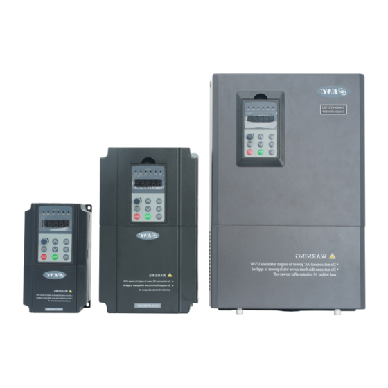
Inverter type and specification 2.6 Appearance and parts name explanation Mounting holes 安装孔 Mounting holes 安装孔 Fig.a Fig.b Fig.2-4 Appearance Table 2-1 Mounting size Fix Hole Inverter model Fig.No (mm) (mm) (mm) (mm) (mm) (mm) (mm) (mm) (mm) (mm) EN600PV-2S0004 EN600PV-2S0007 EN600PV-2S0015 EN600PV-2S0022... -
Page 9: Outer Size Of Keypad And Its Fixing Box (Unit:mm)
Inverter type and specification 2.7 Outer size of keypad and its fixing box (unit:mm) 82.8 17.9 64.5 Fig.2-5 Mounting size of keypad Fig.2-6 Hole size of keypad (1) EN-LCD2 long-distance keypad outer lead, do not support keypad holder installed, only keypad installed support, mounting size refer to Fig.2-5. (2) Except EN-LCD2 long-distance keypad, when other keypad outer lead, user can adjust the hole size under actual situation on keypad or keypad holder;... - Page 10 Inverter type and specification Channel 2 for analog input channel, AI1 can choose 4 ~ 20mA or 0 ~ Analog input channel 10V output , AI2 is differential input channel , 4 ~ 20mA or -10 ~ 10V for option , which can be expanded to channel 4 analog input. 0.1 ~...
-
Page 11: Installation And Wiring
Installation and wiring 3 Installation and wiring 3.1 Main loop terminal wiring (1) Main loop input output terminal show as Table 3-1, 3-2. Table 3-1 EN600 PV main loop input output terminal description Terminal Adapted type Main loop terminal Function description name 1 phase AC input terminal, L1 、... - Page 12 Installation and wiring 3 phase AC input terminal, R 、 S 、 T connect power source External connect to DC reactor External connect to brake ( + ) resistor reverse terminal EN600PV-4T0300 ( - ) DC volt. Positive terminal EN600PV-4T0370 (...
-
Page 13: Basic Running Wiring Diagram
Installation and wiring 3.2 Basic running wiring diagram Brake unit(external connect fitting part) Brake resistance(external connect fitting part) (+) (-) L1 220VAC AC380V L2 220VAC EN600PV 50/0Hz Multi-function Internal optocoupler isolation input X terminal active,electric level support high level and low level Relay load Lower level valid---short circuit slice connect PW and +24V,... - Page 14 Installation and wiring Multifunction input 5 max input frequency: 1KHz Multifunction input 6 Multifunction input 7 Except for X1 ~ X7 function, It can be used as Multifunction input hi-speed pulse input. X8/DI 8/high-speed pulse input Input impedance: 2.2KΩ max input frequency: 50KHz Provide +24V power to external device (...
- Page 15 Installation and wiring retain Auxiliary StandardRS485 interface Twisted-pair cable or shield wire to connect communication interface (2)RS485 crystal outlet CN6 layout as following RS485 terminal CN6 layout 1 2 3 4 5 6 7 8 Name 485+ 485-...
-
Page 16: Run And Operation Explanation For Inverter
Run and operation explanation for inverter 4 Run and operation explanation for inverter 4.1 Run mode EN600PV inverter have 3 kinds of run mode, following is in turn according to their priority, jog run →solar mode→common run. Shown as Fig.4-1. Electrification Waiting state... -
Page 17: Keypad Function Description
Run and operation explanation for inverter 显示电压指示单位(V) Voltage indicator light 显示电流指示单位(A) Current indicator light 显示频率指示单位(Hz) Frequency indicator light 变频器故障报警指示灯 变频器正转指示灯 Failure alarm indicator light Forward run indicator light 模式指示灯 变频器反转指示灯 Mode indicator light Reverse run indicator light Increase key 递增键 编程/退出键... -
Page 18: Led And Indicator Light
Run and operation explanation for inverter To decrease data or function code (to press it continuously can improve Decreasing button decreasing speed) 4.2.3 LED and indicator light 4 status indicator light: they are MOD(mode):ALM (alarm):FWD(forward run):REV(Reverse run)from left to right on the LED: their respective indicating meaning is as shown in Table 4-2. Table 4-2 Status indicator light description Item Function description... - Page 19 Run and operation explanation for inverter Set frequency Output frequency Fig.a Electrification, Fig.b waiting status, display Fig.c run status: display run display 8.8.8.8.8. waiting status parameter status parameter Fig.4-3 Inverter electrification: waiting: run status display (3) Failure alarm display status The inverter enters into failure alarm display status upon detecting failure signal and display failure code sparklingly(as shown in Fig.4-4);...
-
Page 20: User Management Parameters
Run and operation explanation for inverter Second-class menu First class menu ESC/MENU ENTER/DATA Output freq.switch display Para. group Display control ESC/MENU ESC/MENU Waiting status parameter Display or run status parameter display or failure alarm display Fig.4-5 Keypad display status switching (5) Alarm state display When under running and standby situation:It means enter failure alarm display status upon detecting failure... - Page 21 Run and operation explanation for inverter LED displayed content 0.00 C-01 Para. C-02 Para. Key-press operation order C-00 Para. C-05 Para. C-03 ∫…∫ Fig.4-7 Waiting status parameter display operating example (2) Function code parameter setting Take function code F01.01 modified from 5.00Hz to 6.00Hz as example.Boldface in Fig.4-8 shows flickering digit.
- Page 22 Run and operation explanation for inverter of hundred unit of F00.14. (5) Keypad key-press unlocking operation Under keypad-locked situation, press key for more than 5s to unlock the keypad.
-
Page 23: Function Parameter Schedule Graph
Function parameter schedule graph 5 Function parameter schedule graph 5.1 Symbol description × ---- parameter can’t be changed in process of running ○ ---- parameter can be changed in process of running * ---- read-only parameter, unmodifiable 5.2 Function parameter schedule graph F00-System parameter group Function Min. - Page 24 Function parameter schedule graph 32: Process PID deviation (0.01V) 33: Process PID output (0.01Hz) 34: Simple PLC current segment No. 35: External multi-speed current segment No. 36-38: Reserved 39: Current length(m/cm/mm) 40: Accumulate length(m/cm/mm) 41: Current internal count value 42: Current internal time value(0.1s) 43: Run command setup channel (0:keyboard 1: terminal 2: communication) 44: Main frequency provide channel...
- Page 25 Function parameter schedule graph F00.09 C-02 display Same as above ○ parameter selection when stop F00.10 C-03 display Same as above ○ parameter selection when stop F00.11 C-04 display Same as above ○ parameter selection when stop F00.12 C-05 display Same as above ○...
- Page 26 Function parameter schedule graph 1: Keyboard button valid F00.16 Multi-function key 0: Keyboard control→ terminal control→ ○ run command communication control channel switching 1: Keyboard control←→terminal control order selection 2: Keyboard control←→communication control 3: Terminal control←→communication control 0.1 ~ 999.9% F00.17 Motor speed 0.1% 100.0%...
- Page 27 Function parameter schedule graph 1: Parameter upload 2: Parameter download 1 (Without motor parameter) 3: Parameter download 2 (With motor parameter) F01 - Basic Run Function Parameter Group Function Min. Factory Modifi Name Set range code unit default -cation F01.00 Main frequency 0: Operation keyboard digital setup ○...
- Page 28 Function parameter schedule graph setup F01.05 Auxiliary Units digit: power down reserve setup ○ frequency digital 0:Auxiliary frequency power down reserve. control 1:Auxiliary frequency power down no reserve. Tens digit: halt reserve setup 0:Halt auxiliary frequency hold. 1:Halt auxiliary frequency recovery parameter F01.04 F01.06 Main and auxiliary 0:Main frequency (complex frequency of current is...
- Page 29 Function parameter schedule graph valid to keyboard inching command) 0:Forward 1:Reverse Tens digit: for/rev forbid (suitable for all command channel,not include Jog function) 0:For/rev available. 1:Reverse not available (imposing on reverse,stop as the halt mode). 2:Forward not available (imposing on forward,stop as the halt mode) Hundreds digit: Reverse running direction (only valid for keyboard and communication channel)
- Page 30 Function parameter schedule graph F02 - Start, stop, forward/reverse, brake function parameter group Function Min. Factory Modifi Name Set range code unit default -cation F02.00 Start running mode 0: Start from starting frequency × 1: First brake and then start from starting frequency 0.0 ~...
- Page 31 Function parameter schedule graph 3: Degression torque curve 3 (1.2 power) 4: User self-defined setting V/F curve (Confirmed by F03.04~F03.11) 5:V/F Separation control (Voltage channel is determined by F18.22) F03.01 Torque boost mode 0: Manual boost. ○ 1: Auto torque boost F03.02 Torque boost 0.0 ~...
- Page 32 Function parameter schedule graph Asynchronous modulation). F04.11 AVR function 0: No action × 1: Action all the time 2: No action only during deceleration F04.13 Automatic energy- 0: No action × saving operation 1: Action F04.14 Acceleration time 2 0.00Hz ~ upper limit frequency 0.01Hz 0.00Hz ×...
- Page 33 Function parameter schedule graph 2: 1200BPS 3: 2400BPS 4: 4800BPS 5: 9600BPS 6: 19200BPS 7: 38400BPS 8: 57600BPS 9:115200BPS Tens digit: Profibus_DP Baud rate selection 0: 115200BPS 1: 208300BPS 2: 256000BPS 3: 512000BPS Hundreds digit: CanLink and CANopen Baud rate selection 0: 20K 1: 50K 2: 100K...
- Page 34 Function parameter schedule graph Bit1: CX2 virtual input terminal enabled 0: Forbidden 1: Enabled Bit2: CX3 virtual input terminal enabled 0: Forbidden 1: Enabled Bit3: CX4 virtual input terminal enabled 0: Forbidden 1: Enabled Bit4: CX5 virtual input terminal enabled 0: Forbidden 1: Enabled Bit5: CX6 virtual input terminal enabled...
- Page 35 Function parameter schedule graph application parameter 9 F00.00 ~ F26.xx F05.27 Input mapping 0.01 25.00 ○ application parameter 10 F05.28 Setting frequency Display current setting frequency 0.01Hz ○ F05.29 Frequency after current Display the frequency after current acceleration / 0.01Hz ○...
- Page 36 Function parameter schedule graph Curve 2 inflexion setting ~ 100.0% F06.11 Curve 2 Max. setting 0.1% 100.0% ○ 0.0 ~ 100.0% F06.12 Corresponding physical 0.1% 100.0% ○ quantity of curve 2 Max. setting 0.0% ~ curve 3 inflexion 1 setting F06.13 Curve 3 min.
- Page 37 Function parameter schedule graph F07.12 Pulse width input logic 0: Positive logic ○ setting. 1: Negative logic 0.1 ~ 999.9ms F07.13 Max pulse input width 0.1ms 100.0ms ○ 0.0% ~ 100.0% F07.14 Analog input disconnection 0.1% 10.0% ○ detection threshold 0.0 ~...
- Page 38 Function parameter schedule graph selection terminal 3 12: Acceleration/deceleration time selection terminal 4 13: Main and auxiliary frequency operational rule selection terminal 1 14: Main and auxiliary frequency operational rule selection terminal 2 15: Main and auxiliary frequency operational rule selection terminal 3 16: Frequency ascending command(UP) 17: Frequency descending command (DOWN)
- Page 39 Function parameter schedule graph terminal 1 53:Running command Channel selection terminal 2 54:Forward prohibited command (Stop according to the stop mode: invalid for jogging command) 55:Reverse prohibited command (Stop according to the stop mode: invalid for jogging command) 56:Swinging frequency input 57:Resetting state of swinging frequency 58:Interior counter reset end 59:Interior counter input end...
- Page 40 Function parameter schedule graph 1: The lowest priority level Tens digit: Keypad adjustment of display setting (under speed control mode) 0: Display setting frequency 1: Display setting rotation speed F09 - On-off , Analog output function parameter group Function Min. Factory Modifi Name...
- Page 41 Function parameter schedule graph switching Forward and reverse ) 47: Frequency inverter running 1(not jog running) 48: Analog input disconnection signal output 49: X1 Terminal closed valid 50: X2 Terminal closed valid 51~60: Reserved F09.01 Open collector Same as above ×...
- Page 42 Function parameter schedule graph arriving the detection width 0000 ~ FFFF(extension valid) F09.24 positive and 0000 ○ negative logic setup of Output terminal 0.000 ~ 50.000s F09.25 Y1 output closed 0.001s 0.000s ○ delay time 0.000 ~ 50.000s F09.26 Y1 output 0.001s 0.000s ○...
- Page 43 Function parameter schedule graph flux current) 20 ~ 25: Reserved F09.36 Analog output(AO2) Same as above ○ selection F09.37 DO function Same as above ○ selection (with Y4 reuse) 0.0 ~ 20.0s F09.39 Analog output 0.1s 0.0s ○ (AO1) filter time 0.00 ~...
- Page 44 Function parameter schedule graph PLC and multi-speed. 0:Forward 1:Reversal 2:Determine by run command Hundreds digit:ACC/DEC time selection 0: ACC/DEC time 1 1: ACC/DEC time 2 2: ACC/DEC time 3 3: ACC/DEC time 4 4: ACC/DEC time 5 5: ACC/DEC time 6 6: ACC/DEC time 7 7: ACC/DEC time 8 8: ACC/DEC time 9...
- Page 45 Function parameter schedule graph F10.38 Multi- frequency 8 0.00Hz ~ upper limit frequency 0.01Hz 5.00Hz ○ F10.39 Multi- frequency 9 0.00Hz ~ upper limit frequency 0.01Hz 10.00Hz ○ F10.40 Multi- frequency 10 0.00Hz ~ upper limit frequency 0.01Hz 20.00Hz ○ F10.41 Multi- frequency 11 0.00Hz ~...
- Page 46 Function parameter schedule graph 0.00Hz ~ upper limit frequency F11.16 PID regulation lower 0.01Hz 0.00Hz ○ limit frequency F11.17 Integral regulation 0:When integral arrival separate PID threshold ○ selection value,stop integral adjusting 1:When integral arrival separate PID threshold value,continue threshold value adjusting 0.0 ~...
- Page 47 Function parameter schedule graph BIT3:Minimum power protection (A-45) BIT4:Water full protection (A-46) 0:Free stop 1:Deceleration stop F12.10 Photovoltaic time constant 1 ~ 100 ○ F12.11 Sleep voltage 0 ~ 600.0V 0.1V 200.0V ○ F12.13 Awakening voltage 0 ~ 600.0V 0.1V 200.0V ○...
- Page 48 Function parameter schedule graph F12.35 Power curve 3 0.0kw ~ 999.9kw 0.1Kw 2.0Kw ○ F12.36 Power curve 4 0.0kw ~ 999.9kw 0.1Kw 2.5Kw ○ F12.37 Flow curve 0 0.0m3/h ~ 999.9m3/h 0.1m3/h 0.0m3/h ○ F12.38 Flow curve 1 0.0m3/h ~ 999.9m3/h 0.1m3/h 5.0m3/h ○...
- Page 49 Function parameter schedule graph 0: Continue running 1: Shut down according to stopping mode 2: Loop length control Thousands digit: Software reset length (could be cleared by communication) 0: No operation 1: The current length is cleared 2:The current length and total length both cleared F13.14 Record length manage Units digit: Stops the current length ○...
- Page 50 Function parameter schedule graph 5: EAI1 Analog setting(Expansion effective) 6: EAI2 Analog setting(Expansion effective) 7: Rapid pulse setting ( X8 terminal needs to choose the corresponding function) 8:Terminal pulse width setting (X8 terminal needs to choose the corresponding function) Tens digit: Electric torque limit channel selection 0: Digital setting (Determined by F14.09) 1: AI1 analog setting 2: AI2 analog setting...
- Page 51 Function parameter schedule graph F14.16 Forward speed limit 0: Digital setting × channel selection in 1: AI1 Analog setting Torque control mode 2: AI2 Analog setting 3: Terminal UP/DOWN adjustment setting 4:Communication provision(Communication address: 1D0A). 5: EAI1 Analog setting(expansion effective) 6: EAI2 Analog setting(expansion effective) 7: Rapid pulse setting(X8 terminal needs to choose the corresponding function)
- Page 52 Function parameter schedule graph rated current motor type 0.00 ~ 600.00Hz F15.04 Asynchronous motor 0.01Hz Base on × rated frequency motor type 0 ~ 60000r/min F15.05 Asynchronous motor 1r/min Base on × rated rotational speed motor type 1 ~ 7 F15.06 Asynchronous motor ×...
- Page 53 Function parameter schedule graph F18.03 Digital frequency Units digit: Keyboard UP/DW integral control 0000 ○ integral function 0: Integral function selection 1: No integral function Tens digit: Terminal UP/DW integral control 0: Integral function 1: No integral function Hundreds digit: Keyboard shuttle knob enable (shuttle keyboard effective) 0: The shuttle knob is valid in the monitoring interface...
- Page 54 Function parameter schedule graph 0: Invalid 1: Valid Thousands digit : in torque control mode,Low torque given PWM blocking function (Thousands digit is valid when F00.24=1) 0: Invalid F18.17 cooling fan control Units digit: Fan control mode ○ selection 0: Smart fan 1: Inverter is running all the time after power on 2: No running for fan, but it starts automatically when the temperature is higher than 75 degree.
- Page 55 Function parameter schedule graph 10.0 ~ 2000.0%(motor rated current) F19.04 Motor overload 0.1% 100.0% ○ protection coefficient F19.05 Inverter overload 0: Detection all the time ○ pre-alarm detection 1: Detection as constant velocity selection 20 ~ 180% (Inverter rated current) F19.06 Inverter overload 130%...
- Page 56 Function parameter schedule graph 0.00 ~ 99.99Hz/s F19.19 Frequency droop 0.01Hz/s 10.00Hz/s × rate when instant power off 0.00 ~ 10.00s F19.20 Voltage rebound 0.01s 0.10s × estimate time when instant power off 60 ~ 100% (Rated busbar voltage) F19.21 Action estimate ×...
- Page 57 Function parameter schedule graph 2:Fault, Free halt Hundreds digit: Contactor abnormal action 0:Alarm,Continue run 1:Alarm,Stop run as halt mode 2:Fault,Free halt Thousands digit: Running lack-Voltage fault display action selection. 0: No detection 1:fault,free halt F19.35 Fault indication and Units digit: fault indication selection during the ×...
- Page 58 Function parameter schedule graph function selection 0 ~ 60 F20.05 Virtual output VDO1 ○ function selection 0 ~ 60 F20.06 Virtual output VDO2 ○ function selection 0 ~ 60 F20.07 Virtual output VDO3 ○ function selection 0 ~ 60 F20.08 Virtual output VDO4 ○...
- Page 59 Function parameter schedule graph 1:Negative logic F21 - Extended AI parameter group Function Min. Factory Modifi Name Set range code unit default -cation 0 ~ 9.999s F21.00 EAI1 Filter time 0.001s 0.050s ○ 0 ~ 9.999 F21.01 EAI1 Gain 0.001s 1.003 ○...
- Page 60 Function parameter schedule graph F00.00 ~ F25.xx F25.13 User Function Code 14 0.01 25.00 ○ F00.00 ~ F25.xx F25.14 User Function Code 15 0.01 25.00 ○ F00.00 ~ F25.xx F25.15 User Function Code 16 0.01 25.00 ○ F00.00 ~ F25.xx F25.16 User Function Code 17 0.01...
- Page 61 Function parameter schedule graph 36:Capacitor overheat(few mode with overheat protection) 37:Reserved 38:Over-speed protection 39:Protection when speed deviation is too large 40:Reserved 41:Analog channel disconnected protection 42 ~ 50: Reserved F26.01 The last two fault Same as above records F26.02 The last three fault Same as above records F26.03...
- Page 62 Function parameter schedule graph C - Monitor Function Parameter Group Function Min. Factory Modifi Name Set range code unit default -cation C-00 Display the parameter of F00.01,F00.07 definition C-01 Display the parameter of F00.02,F00.08 definition C-02 Display the parameter of F00.03,F00.09 definition C-03 Display the parameter of...
-
Page 63: Debugging Specification
Debugging specification 6 Debugging specification Detailed function description of Solar inverter Code NO. Description Setup Range/explanation Factory set up 6.1.1 System Parameter Group:F00 C-00 display parameter F00.01 Range:0~65 selection when operation C-01 display parameter F00.02 Range:0~65 selection when operation C-02 display parameter F00.03 Range:0~65 selection when operation... -
Page 64: On-Off Input Function Parameter Group: F08
Debugging specification The above parameter display when inverter stop by C-00~C-05 parameter group, pressing to switch between these parameters. Pressing and then return to C-00 parameter monitor. For example: pressing parameter switch from C-00 to C-01, continuous pressing the same button: parameter switch from C-01 to C-02: then pressing return to C-00 parameter monitor. -
Page 65: Photovoltaic Special Function Parameter Group:f12
Debugging specification 6.1.3 Photovoltaic special function parameter group:F12 F12.00 Photovoltaic water supply model Range: 0~2 0:Pv parameter set is invalid, frequency conversion enters debugging mode. 1:Mppt Mode 2:CVT Mode. When F12.00=1 and 2, the frequency converter runs in photovoltaic mode, and when F12.00=2, the frequency converter runs in CVT mode. - Page 66 Debugging specification 0:Free stop. 1:Slowing down F12.10 Photovoltaic time constant Range:1~100 F12.11 Sleep voltage Range:0.0~600.0V 200.0V F12.13 Wake-up voltage Range:0.0~600.0V 200.0V F12.14 Wake-up time Range:0.0~6000.0s 10.0s Sleep function: when the dc bus voltage is less than F12.11, the frequency converter will enter the sleep state and the operating frequency will be reduced to 0.00Hz to achieve the purpose of energy saving and motor protection, and A-47 warning will be displayed.
- Page 67 Debugging specification F12.21=0 or F12.22=0, this function is invalid. Range: Ones:0、1 Tens:0、1 F12.24 Alarm recovery mode 0000 Hundereds:0、1 Thousands:0、1 This parameter defines the frequency converter action type under the condition of low frequency protection, dry pumping protection, overcurrent protection and minimum power protection.
-
Page 68: Ooperation Instructions For Asynchronous Motor Pumps
Debugging specification F12.38 Flow curve 1 Range :0.0~999.9m 5.0m F12.39 Flow curve 2 Range :0.0~999.9m 10.0m F12.40 Flow curve 3 Range :0.0~999.9m 15.0m F12.41 Flow curve s4 Range :0.0~999.9m 20.0m F12.32 ~ F12.41 defines the PQ curve, which can be used for users to set 5 groups of PQ corresponding points according to the water pump situation to realize real-time flow rate, daily flow rate and cumulative flow rate calculation. -
Page 69: Introduction Of Protection Function Of Photovoltaic Inverter
Debugging specification 6.3 Introduction of protection function of photovoltaic inverter (1) Sleep function Under the photovoltaic mode, when the dc bus voltage is less than F12.11, the frequency converter will enter the sleep state and the operating frequency will be reduced to 0.00Hz to achieve the purpose of energy saving and motor protection, and A-47 warning will be displayed. -
Page 70: Troubleshooting
Troubleshooting 7 Troubleshooting 7.1 Failure and countermeasure Possible failure types in EN600PV are shown in Table 7-1, the fault types including fault and alarm two kinds. Such as if inverter fault display E-XX, while the corresponding alarm is displayed in A-XX. Once the inverter failure , fault types are stored in the F26 fault recording parameter group, and if alarm, alarm status has been revealed, until the alarm source release, alarm status are not logged to the F26 parameter group. - Page 71 Troubleshooting E-07 Inverter control Unwonted input voltage Check input power supply or look power supply for service overvoltage E-08 Low-voltage when Input voltage is too low Check the input voltage running E-09 Inverter overload Acc time is set to too short Prolong accelerating time protection DC injection braking is too big...
- Page 72 Troubleshooting abnormal and the current waveform is abnormal. Auxiliary power supply is Look for the service from damaged, drive voltage is under manufactur voltage Look for the service from The control board is abnormal manufactur Motor short circuit to ground The replacement of cable or motor Hall component is damaged or Short circuit to ground...
- Page 73 Troubleshooting Check external feedback signal Feedback signal disconnection wiring The main control board is Look for service from manufacturer abnormal. or agent PID error amount abnormal detect threshold setting is To reset the relevant parameters PID error E-24 unreasonable (A-24) amount abnormal The main control board is Look for service from manufacturer...
-
Page 74: Failure Record Lookup
Troubleshooting The physical quantity detected by Analog channel AI1 or AI2 is not within the Reasonably control the physical E-41 disconnection reasonable range, or the circuit of quantity measured by AI1 or AI2 AI1 or AI2 is in poor contact. and check the wiring of AI1 or AI2. -
Page 75: Failure Reset
Troubleshooting F26.06 Output current at previous failure F26.15 Module temp. at previous 2 failure Input terminal state of previous 2 F26.07 DC bus volt. at previous failure F26.16 failure F26.08 Module temp. at previous failure F26.17 Running time of previous 2 failure 7.3 Failure reset (1) Before reset you must find out reason of failure downright and eliminate it,otherwise may cause permanent damage to the inverter. -
Page 76: Maintenance
Maintenance 8 Maintenance 8.1 Routine maintenance When you use this series you must assemble and operate it according to demand listed in this “service manual” strictly. During run state, temperature, humidity, vibration and aging parts will affect it, which may cause failure of the inverter. To void this, it is recommended to perform routine inspections and maintenance. -
Page 77: Storage
Maintenance a. If did not use the inverter according to service manual strictly or did not use it under ambient demanded in service manual, which cause failure. b. Failure caused by applying the inverter to non-normal function; c. Failure caused by self-repair, refit which is not already allowed; d. -
Page 78: Appendix A Modbus Communication Protocol
Modbus communication protocol Appendix A Modbus Communication Protocol A.1 Summary We provide general RS485 communication interface in our inverters for the user. Through this communication interface upper device (such as HMI, PC, PLC controller and etc.) can perform centralized monitor to the inverter (such as to set inverter parameter, control run of inverter, read work state of the inverter). - Page 79 Modbus communication protocol F05.00 Protocol 0:Modbus protocol × selection 1:Reserved 2:Profibus protocol(expansion is valid) 3:CanLink protocol(expansion is valid) 4:CANopen protocol(expansion is valid) 5:free protocol 1(revision all the parameter of EN600PV is valid) 6: free protocol 2(only revising part Parameter of EN600PV is valid) Remark: expansion card is needed when Select 2,3,4 communication...
- Page 80 Modbus communication protocol CRC check value high byte Closing Flag 3.5 characters time pause Regarding generation method of CRC check value, please refer to check mode Section. ASCII frame format as the table below: Frame Header ‘:’ ( 0x3A ) Slave address Hi Slave address: Combined by 2 ASCII code Slave address Lo...
- Page 81 Modbus communication protocol A.5.3 Host write slave parameter Command code 06H. Host can write an parameter by initiating a communication transaction . E.g.,The decimal system 5000 (1388H) written to the inverter 0101H address whose slave address is 02 , host command including: Parameter address high byte Parameter address low byte Parameter value high byte...
- Page 82 Modbus communication protocol writing F01.02 hundreds=1:10000representsF01.11 BIT0:bus volt. set up BIT1:common run command valid BIT2:jog run command valid BIT3:running BIT4:current running direction is reverse BIT5:operating instruction is reverse BIT6:decelerating & braking BIT7:accelerating Inverter status 1E02H Reading only BIT8:decelerating BIT9:alarm BIT10:fault BIT11:current limiting BIT12:fault self-recovery BIT13:self tuning...
- Page 83 Modbus communication protocol given value Communication Range:0 ~ 4000 ( 4000 represents EAO2 1D05H Read-write 10.00V or 20.00mA ) given value Communication DO Range:0 ~ 4000 ( 4000 represents 1D06H Read-write given value 10.00V or 20.00mA ) Communication EDO Range:0 ~ 4000 ( 4000 represents 1D07H Read-write given value...
- Page 84 Modbus communication protocol 0x05 Not allow to modify parameters 0x06 Register number read illegal A.8 Data frames examples A.8.1 RTU Mode 1. Start #1 inverter running Register Register Data Data Slave Order Data Field address address High Address code low bit high bit High byte Low byte...
- Page 85 Modbus communication protocol A.8.2 ACSII Mode Host read Slave, Command code: 03 The host frame The host frame format Send byte Remark: Begin symbol: The lower computer judge the frame header of ASCII based on this. It is:’:’ Slave address: ...
- Page 86 Modbus communication protocol Begin code: The lower computer judge the frame of ASCII frame. This is :’:’ Slave address: Single inverter ID code , range:0 ~ 247. Thereinto, address 0 is broadcast address. Broadcast address can control all the lined Slave simultaneously , and the Slave will not send back any Data to the host.
- Page 87 Modbus communication protocol The main frame writes slave address single register, command code: 06 The host frame The host frame format Send byte Remark: Slave address : Single inverter ID code , range:0 ~ 247. Thereinto, address 00 is broadcast address. ...
- Page 88 Modbus communication protocol The new value of revised parameter. Checksum : From “slave address” to the character before checksum, the LRC checksum of the character string. The followings are the example of command frame and return frame, all the Data are ASCII character.
- Page 89 Modbus communication protocol crc_value >>= 1; crc_value ^= 0xA001; else crc_value >>= 1; return(crc_value);...
-
Page 90: Appendix B Accessories Selection
Accessories Selection Appendix B Accessories Selection B.1 Selection for communication expansion card: At present, our company can provide our customers with the following several kinds of communication expansion cards. Model NO. Description Remark PROFIBUS-DP expansion card ( for machine which power range of EN-PRO1 Optional 15KW and below )... - Page 91 Shenzhen Encom Electric Technologies CO., LTD. Address: 5F, Bldg.4, Minqi Technology Park, Lishan Rd., Nanshan Area, Shenzhen 518055, China Website: www.encvfd.com E-mail: encvfd@encvfd.com encvfd@enc.net.cn Tel: +86-755-26984485 Fax: +86-755-26985120...
Need help?
Do you have a question about the EN600PV Series and is the answer not in the manual?
Questions and answers