Table of Contents
Advertisement
Quick Links
Advertisement
Table of Contents

Subscribe to Our Youtube Channel
Related Manuals for Crestron TST-902


Summary of Contents for Crestron TST-902
- Page 1 TST-902 8.7 in. Wireless Touch Screen Product Manual Crestron Electronics, Inc.
- Page 2 Other trademarks, registered trademarks, and trade names may be used in this document to refer to either the entities claiming the marks and names or their products. Crestron disclaims any proprietary interest in the marks and names of others. Crestron is not responsible for errors in typography or photography.
-
Page 3: Table Of Contents
Contents Overview Features TST-902 Features TST-902-BTP Features TST-902-DS Features TST-902-DSW Features TST-902-DSW-BB Features TST-902-DSW-BBI Features TST-902-DSW-PMK Features TST-902-DSW-WMKM Features TST-902-DSW-WMKT Features Specifications TST-902 Specifications Product Specifications Dimension Drawings TST-902-BTP Specifications TST-902-DS Specifications Product Specifications Dimension Drawings TST-902-DSW Specifications Product Specifications... - Page 4 In the Box Install the Battery Pack Place the TST-902 TST-902-BTP Installation In the Box Remove the Existing Battery Pack Install the TST-902-BTP Charge the TST-902-BTP Store the TST-902-BTP Recycle the TST-902-BTP TST-902-DS Installation In the Box Install the TST-902-DS...
- Page 5 RF Setup Audio Setup Display Setup Standby Timeout Wi-Fi Setup Diagnostics About Perform a Factory Restore Operation Resources Crestron Support and Training Programmer and Developer Resources Product Certificates Related Documentation Product Manual — Doc. 7750C Contents • v...
-
Page 6: Overview
Its large-capacity, rechargeable battery affords several hours of operation between charges. Dual-mode wireless performance with roaming capability assures dependable connectivity throughout a commercial facility or home. This section provides the following information: Features on page 2 Product Manual — Doc. 7750C TST-902 • 1... -
Page 7: Features
Features Refer to the following sections for more information on the features provided by the TST-902 and its accessories. TST-902 Features on page 3 TST-902-BTP Features on page 7 TST-902-DS Features on page 8 TST-902-DSW Features on page 9 TST-902-DSW-BB Features on page 10... -
Page 8: Features
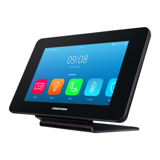
Featuring a high-contrast 8.7 in. capacitive touch screen with Smart Graphics® technology, the TST-902 allows completely customizable control over media presentation and teleconferencing systems, lighting and shades, HVAC, home theater, and a host of other technologies. Additional advanced features include voice commands for controlling touch screen functions, full-motion streaming video from cameras and other sources, Rava®... - Page 9 Voice Recognition With built-in voice recognition, spoken commands can be issued to the TST-902 to quickly turn devices on or off, select and play a specific media source, change the channel, choose a lighting scene, lower the window shades, lock the doors, arm the security system, or enter a password.
- Page 10 Crestron Extended (ER) Range 2.4 GHz RF and Wi-Fi® wireless technologies. NOTE: Every TST-902 installation requires a Crestron ER wireless gateway to provide essential wireless capability to the touch screen. The TST-902 will not function over Wi-Fi communications alone. Extended Range RF (Required): Primary functionality is supported via Crestron ER (Extended Range) wireless communications, providing seamless touch screen control with true feedback.
- Page 11 The TST-902 includes a table dock for charging its internal battery while simultaneously allowing it to be used as a stationary tabletop touch screen. The table dock holds the TST-902 firmly at a fixed upright angle while docked, and allows it to be taken off at any time for portable use. Its sleek appearance makes it a perfect fit for any home or office.
-
Page 12: Tst-902-Btp Features
Intelligent power management and Lithium Ion battery technology work together to provide a lightweight, compact battery with long battery life. NOTE: Lithium Ion batteries must be stored at 50% charge and cycled every three months. Product Manual — Doc. 7750C TST-902 • 7... -
Page 13: Tst-902-Ds Features
The table dock holds the TST-902 firmly at a fixed upright angle while docked, and allows it to be taken off at any time for portable use. Its sleek appearance makes it a perfect fit for any home or office. -
Page 14: Tst-902-Dsw Features
Note: 1. The TST-902-DSW docking mechanism works as intended when mounted in a standard vertical orientation (such as within a wall). The maximum allowable tilt is 16° back. The mechanism will not eject properly at an angle greater than this. -
Page 15: Tst-902-Dsw-Bb Features
TST-902-DSW wall dock. Designed for preconstruction applications, the TST-902-DSW-BB can be fastened to the left or right-hand stud of a framed wall prior to drywall installation. Conduit knockouts are provided on the top and bottom of the back box. A blank cover plate is also included to temporarily cover the back box opening during construction. -
Page 16: Tst-902-Dsw-Bbi Features
TST-902-DSW wall dock. The TST-902-DSW-BBI is designed specifically for installation in masonry and concrete applications. Conduit knockouts are provided on the top and bottom of the back box. Product Manual — Doc. 7750C... -
Page 17: Tst-902-Dsw-Pmk Features
TST-902-DSW wall dock. The TST-902-DSW-PMK can be fastened to the left or right-hand stud of a framed wall prior to drywall installation. A blank cover plate is also included to temporarily cover the back box opening during construction. -
Page 18: Tst-902-Dsw-Wmkm Features
TST-902-DSW wall dock in an existing framed wall or similar flat surface. Designed for postconstruction applications, the TST-902-DSW-WMKM includes a mud ring to compensate for any imperfections in the drywall cutout. Product Manual — Doc. 7750C TST-902 • 13... -
Page 19: Tst-902-Dsw-Wmkt Features
TST-902-DSW wall dock in an existing framed wall or similar flat surface. Designed for postconstruction applications, the TST-902-DSW-WMKM includes a trim ring to provide a smooth edge around the drywall cutout. 14 • TST-902 Product Manual — Doc. 7750C... -
Page 20: Specifications
Specifications Refer to the following sections for more information on specifications for the TST-902 and its accessories. TST-902 Specifications on page 16 TST-902-BTP Specifications on page 21 TST-902-DS Specifications on page 22 TST-902-DSW Specifications on page 24 TST-902-DSW-BB Specifications on page 28... -
Page 21: Specifications
TST-902 Specifications Product specifications for the TST-902 are provided below. Product Specifications Touch Screen Display Display Type TFT active matrix color LCD Size 8.74 in. (222 m) diagonal Resolution 1008 x 588 pixels Brightness 300 nits (cd/m Contrast 700:1 Color Depth 24 bit, 16.7M colors Illumination LED backlit... - Page 22 64 and 128-bit WEP, WPA and WPA2-PSK with TKIP and AES Range Up to 50 ft (15 m); Subject to site-specific conditions Gateway Requires a 802.11b/g/n wireless access point and Ethernet-enabled Crestron control system Handoff Supports handoff between a maximum of 4 Wi-Fi access points Wired Communications USB client for console only (installer setup and firmware updates)
- Page 23 Power (1) 1.7 x 4.0 mm DC power connector; 24VDC power input (for included power pack) Docking Connector (3) Contacts; Mates with docking port on included TST-902-DS docking station Headphones (1) 3.5 mm TRS miniphone jack; Stereo headphone output (1) Mini Type-B USB console port; Located behind battery compartment cover for installer use only...
-
Page 24: Dimension Drawings
Height 6.44 in. (164 mm) Width 10.37 in. (264 mm) Depth 0.74 in. (19 mm) Weight 28.5 oz (808 g) Compliance IC, CE, FCC Part 15 Class B digital device To search for product certificates, refer to support.crestron.com/app/certificates. Dimension Drawings Product Manual — Doc. 7750C TST-902 • 19... - Page 25 7. ER (Extended Range) RF wireless communication supports basic wireless touch screen functionality, and is required for all applications. For advanced functionality including streaming video, voice recognition, web browsing, and dynamic graphics, Wi-Fi wireless communication is also required (dual-mode). The TST-902 will not work with Wi-Fi alone. 20 • TST-902...
-
Page 26: Tst-902-Btp Specifications
TST-902-BTP Specifications Product specifications for the TST-902 are provided below. Battery Composition Lithium Ion Output Voltage 7.4V Capacity 9100 mAh Usage per Charge 3000 hours typical under normal use (10% active duty cycle with standby/power down turned on); 9 hours continuous when using default settings... -
Page 27: Tst-902-Ds Specifications
TST-902-DS Specifications Product specifications for the TST-902-DS are provided below. Product Specifications Connectors Power (1) Attached 6 ft (1.83 m) cable with inline 1.7 x 4.0 mm DC power connector; 24VDC power input (for included power pack) Power Power Pack (Included) Input: 0.6A (maximum) @ 100–240VAC, 50/60 Hz;... -
Page 28: Dimension Drawings
Dimension Drawings Product Manual — Doc. 7750C TST-902 • 23... -
Page 29: Tst-902-Dsw Specifications
) maximum Controls OPEN (1) Push button, accessible when touch screen is not docked; Releases the docking mechanism that allows the TST-902 to be docked Power Requirements Cresnet® Power Usage 11 W (0.46A @ 24VDC) with touch screen docked NOTE: May be powered by Cresnet network power or a dedicated Cresnet power supply. Does not support Cresnet data communication (only power). - Page 30 IC, CE, FCC Part 15 Class B digital device To search for product certificates, refer to support.crestron.com/app/certificates. Product Manual — Doc. 7750C TST-902 • 25...
-
Page 31: Dimension Drawings
Dimension Drawings 26 • TST-902 Product Manual — Doc. 7750C... - Page 32 Note: 1. The TST-902-DSW docking mechanism works as intended when mounted in a standard vertical orientation (such as within a wall). The maximum allowable tilt is 16° back. The mechanism will not eject properly at an angle greater than this.
-
Page 33: Tst-902-Dsw-Bb Specifications
TST-902-DSW-BB Specifications Product specifications for the TST-902-DSW-BB are provided below. Product Specifications Construction Metal box, front mounting plate with integral stud mounting flange, metal cover plate Dimensions Height 9.01 in. (229 mm) Width 13.65 in. (347 mm) Depth 3.32 in. (85 mm) To search for product certificates, refer to support.crestron.com/app/certificates. -
Page 34: Tst-902-Dsw-Bbi Specifications
TST-902-DSW-BBI Specifications Product specifications for the TST-902-DSW-BBI are provided below. Product Specifications Construction Metal box Dimensions Height 197 mm (7.74 in.) Width 281 mm (11.05 in.) Depth 91 mm (3.56 in.) To search for product certificates, refer to support.crestron.com/app/certificates. Dimension Drawings Product Manual — Doc. 7750C... -
Page 35: Tst-902-Dsw-Pmk Specifications
TST-902-DSW-PMK Specifications Product specifications for the TST-902-DSW-PMK are provided below. Product Specifications Construction Metal mounting plate and cover plate Dimensions Height 8.82 in. (224 mm) Width 13.59 in. (346 mm) To search for product certificates, refer to support.crestron.com/app/certificates. Dimension Drawings 30 • TST-902 Product Manual — Doc. 7750C... -
Page 36: Tst-902-Dsw-Wmkm Specifications
TST-902-DSW-WMKM Specifications Product specifications for the TST-902-DSW-WMKM are provided below. Product Specifications Construction Metal mounting plate and mud ring Dimensions Height 8.82 in. (224 mm) Width 12.46 in. (316 mm) NOTE: Dimensions shown are overall. Refer toTST-902-DSW-WMKM Installation on page 66 actual cutout dimensions, clearances, and complete mounting instructions. -
Page 37: Dimension Drawings
Dimension Drawings 32 • TST-902 Product Manual — Doc. 7750C... -
Page 38: Tst-902-Dsw-Wmkt Specifications
TST-902-DSW-WMKT Specifications Product specifications for the TST-902-DSW-WMKT are provided below. Product Specifications Construction Metal mounting plate and trim ring Dimensions Height 8.82 in. (224 mm) Width 12.00 in. (305 mm) NOTE: Dimensions shown are overall. Refer to TST-902-DSW-WMKT Installation on page 76 actual cutout dimensions, clearances, and complete mounting instructions. -
Page 39: Dimension Drawings
Dimension Drawings 34 • TST-902 Product Manual — Doc. 7750C... -
Page 40: Installation
Installation Refer to the following sections for instructions on how to install the TST-902 and its accessories. TST-902 Installation on page 36 TST-902-BTP Installation on page 40 TST-902-DS Installation on page 44 TST-902-DSW Installation on page 46 TST-902-DSW-BB Installation on page 53... -
Page 41: Installation
1. Insert the provided t-pin tool into one of the two tab release holes on the rear of the TST-902, and then slide the bottom cover downward to release the tab on that side. 2. Repeat step 1 for the other tab release hole. - Page 42 4. Lift the bottom cover upward to remove it from the touch screen. 5. Orient the battery pack so that its "Lift to Remove" tag is visible and the multipin connector is positioned to its left. Product Manual — Doc. 7750C TST-902 • 37...
- Page 43 Allow the TST-902 to charge overnight completely before removing it from its dock. If the TST-902 is in use while charging, the battery may take up to six hours to charge. The battery pack should be replaced every 18 to 24 months under normal usage. For...
-
Page 44: Place The Tst-902
Place the TST-902 The TST-902 can be used as a portable tablet-style device, or it can it can be placed within the included table dock or optional wall dock for use as a stationary touch screen. To place the TST-902 within the included table dock, refer to... -
Page 45: Tst-902-Btp Installation
Tool, T-Pin (2020478) Remove the Existing Battery Pack The TST-902 battery pack should be replaced every 18 to 24 months under normal usage. The TST-902-BTP installs in place of the existing battery pack. CAUTION: Note the following to avoid damage to the TST-902-BTP or the touch screen: The TST-902 touch screen is sensitive to electrostatic discharge (ESD). - Page 46 5. Pull the "Lift to Remove" tag on the battery gently to unseat it from the touch screen. 6. Disconnect the battery pack wire harness from the multipin connector on the touch screen. Product Manual — Doc. 7750C TST-902 • 41...
-
Page 47: Install The
Charge the TST-902-BTP Once the TST-902-BTP has been installed, it can be charged by placing the TST-902 in its included table dock (TST-902-DS) or the optional wall dock (TST-902-DSW, not included). -
Page 48: Store The
NOTES: Allow the TST-902-BTP to charge overnight completely before removing it from its dock. If the touch screen is in use while charging, the TST-902-BTP may take up to six hours to charge. Store the TST-902-BTP The TST-902-BTP can be stored in a temperate, dry location (removed from the touch screen and docking station) for up to 3 months without risking significant, irreversible performance degradation. -
Page 49: Tst-902-Ds Installation
Power Cord, 6 ft, 7 in. (2.0 m) (2001134) Power Supply, 24VDC @ 0.75A, 100–240VAC (2048337) Install the TST-902-DS Place the TST-902-DS on a flat, level surface. The only required connection is from the fixed 6 ft (1.83 m) power cord on the TST-902-DS to the included power pack. NOTES: Use Crestron power supplies for Crestron equipment. - Page 50 After power has been applied to the TST-902-DS, place the TST-902 touch screen on the TST-902-DS by aligning its three charging contacts with the bottom of the charging dock. The touch screen should be seated firmly on the charging dock once attached, and the touch screen battery will begin to charge.
-
Page 51: Tst-902-Dsw Installation
TST-902-DSW Installation Use the following procedures to install the TST-902-DSW. NOTE: The TST-902-DSW wall dock is designed for flush-mount installation in a flat, vertical wall structure. Installation of the wall dock requires additional mounting hardware (not included): TST-902-DSW-BB and TST-902-DSW-BBI back boxes are available for both framed and masonry construction. -
Page 52: Install The
NOTE: The maximum wire size for the power connection is 18 AWG. 2. While holding the TST-902-DSW, connect the flying leads from the wiring to the 2-pin power connector (24 G) on the rear of the TST-902-DSW. 3. Attach the TST-902-DSW to the mounting hardware using the four 6-32 x 1-1/2 in. screws. - Page 53 NOTE: If the bezel must be removed for any reason, disconnect this cable carefully prior to removal. 5. Attach the bezel to the TST-902-DSW using the four 6-32 x 3/4 in. screws, but do not tighten the screws. Refer to the illustration below step 7.
- Page 54 7. Attach the four plastic plugs to cover the screws. Each plug should be pushed fully into its opening so that the plug is recessed from the bezel front surface. Product Manual — Doc. 7750C TST-902 • 49...
-
Page 55: Dock The Touch Screen
Then, push the cradle back into place to close it. Dock the Touch Screen To dock the TST-902 touch screen once the TST-902-DSW has been installed: 1. Push the release button on the right of the bezel to open the cradle. - Page 56 1. Insert the provided release lock key into the gap between the top of the touch screen and the TST-902-DSW. Ensure that the machined text on the key is facing upward. 2. Rotate the key downward as shown in the following illustration.
- Page 57 3. Remove the key to open the cradle so that the touch screen can be removed. 52 • TST-902 Product Manual — Doc. 7750C...
-
Page 58: Tst-902-Dsw-Bb Installation
NOTES: Ensure the chosen mounting location allows for an air gap of at least 12 in. (305 mm) in the wall cavity above and below the TST-902-DSW for heat dissipation. Depending on the installation, forced venting may be required. The knockout holes are intended for Class 2 wiring and are 1-1/8 in. (29 mm) in diameter. - Page 59 3. Verify that the back box is level prior to proceeding with the rest of the installation. 4. Attach the TST-902-DSW-BB to the left or right side of the stud with four standard drywall screws or nails (not included).
- Page 60 6. Route any wiring for the TST-902-DSW through the appropriate knockout(s) on the back box. 7. Once drywall is installed over the back box, use a standard drywall saw to cut the drywall along the inside edge of the front of the back box. The labels on the front of the back box indicate the perimeter of the drywall cutout.
- Page 61 NOTE: The four tapped holes on the front of the back box must be exposed in order to accept the TST-902-DSW mounting screws. These holes are located along the top and bottom of the drywall opening. The notch at the top center of the back box must also be exposed to accommodate the TST-902-DSW locking latch.
- Page 62 Product Manual — Doc. 7750C TST-902 • 57...
-
Page 63: Tst-902-Dsw-Bbi Installation
No minimum clearances are required. 4. Mount the TST-902-DSW-BBI into the cutout in the mounting surface as shown in the following illustration. Ensure the arrow on the label inside the back box is facing upward prior to installation. - Page 64 TST-902-DSW on page 47 using the included 6-32 x 1-1/2 in. screws. Product Manual — Doc. 7750C TST-902 • 59...
-
Page 65: Tst-902-Dsw-Pmk Installation
For example, installation onto steel studs will require a different type of screw than installation onto wooden studs. 1. Position the TST-902-DSW-PMK mounting bracket against the front edge of the stud. Ensure the extended edge of the mounting bracket is aligned with the front edge of the stud. - Page 66 3. Attach the mounting bracket to the left or right side of the stud with two standard drywall screws or nails (not included). 4. Secure the wire jumper to the bottom of the mounting bracket as shown in the following illustration. Product Manual — Doc. 7750C TST-902 • 61...
- Page 67 5. Route any wiring for the TST-902-DSW through the opening in the mounting bracket and secure them into the wire jumper. 62 • TST-902 Product Manual — Doc. 7750C...
- Page 68 NOTE: The four tapped holes on the front of the mounting bracket must be exposed in order to accept the TST-902-DSW mounting screws. These holes are located along the top and bottom of the drywall opening. The notch at the top center of the mounting bracket must also be exposed to accommodate the TST-902-DSW locking latch.
- Page 69 8. Remove the cover plate and 6-32 x 1-1/2 in. screws (if used), and then install the TST-902-DSW wall dock into the mounting bracket as described in Install the TST-902-DSW on page 47 with the 6-32 x 1-1/2 in. screws. 64 • TST-902 Product Manual — Doc. 7750C...
- Page 70 Product Manual — Doc. 7750C TST-902 • 65...
-
Page 71: Tst-902-Dsw-Wmkm Installation
#2 Phillips screwdriver Tools and materials for applying a drywall joint compound Additionally, a cutout template is provided with the TST-902-DSW-WMKM that can be used when making the drywall cutout for the mounting hardware. The dimensions for the cutout template are provided below as a reference (not to scale). -
Page 72: Install The Mounting Kit
NOTES: Ensure the chosen mounting location allows for an air gap of at least 12 in. (305 mm) in the wall cavity above and below the TST-902-DSW for heat dissipation. The TST-902-DSW-WMKM has been optimized for mounting into drywall that is 5/8 in. (15 mm) thick, though it can also be mounted into drywall that is between 1/2 in. - Page 73 3. Repeat steps 1–2 to attach the second adjustment plate to the bottom of the mounting plate. 68 • TST-902 Product Manual — Doc. 7750C...
- Page 74 5. Using a drywall saw (or equivalent), a level, and the provided cutout template, create a cutout in the drywall for the mounting hardware. Refer to the illustration in Prepare for Installation on page 66 for cutout dimensions. Product Manual — Doc. 7750C TST-902 • 69...
- Page 75 NOTE: Ensure that the cutout is as level and smooth as possible before proceeding. The mounting plate allows only for minor adjustments once installed. 6. Insert the mud ring into the drywall cutout. 70 • TST-902 Product Manual — Doc. 7750C...
- Page 76 Refer to the following illustration. NOTE: The mounting plate and adjustment plate assembly has a slight amount of play. This is normal, as it allows for minor adjustments to be made to the TST-902-DSW during installation. Product Manual — Doc. 7750C TST-902 • 71...
- Page 77 9. Use four standard drywall screws to loosely secure the mud ring to the mounting plate and adjustment plate assembly. The screws must pass through the clearance holes in the mounting plate to be secured in the extruded holes of the adjustment plate. 72 • TST-902 Product Manual — Doc. 7750C...
- Page 78 10. Verify that the mounting hardware is level, and then hand tighten the drywall screws using a #2 Phillips screwdriver so that they dimple slightly into the holes in the mud ring. CAUTION: Do not overtighten the screws, as this may damage the mounting hardware. Product Manual — Doc. 7750C TST-902 • 73...
- Page 79 11. Route any wiring for the TST-902-DSW through the opening in the mounting hardware. 12. Apply joint compound as needed to finish the cutout. 74 • TST-902 Product Manual — Doc. 7750C...
- Page 80 The notch at the top center of the mud ring must also be exposed to accommodate the TST-902-DSW locking latch. 13. After the joint compound has dried, install the TST-902-DSW wall dock into the mud ring as described in Install the TST-902-DSW on page 47 with the 6-32 x 1-1/2 in.
-
Page 81: Tst-902-Dsw-Wmkt Installation
Drywall saw (or equivalent) Level Additionally, a cutout template is provided with the TST-902-DSW-WMKT that can be used when making the drywall cutout for the mounting hardware. The dimensions for the cutout template are provided below as a reference (not to scale). -
Page 82: Install The Mounting Kit
NOTES: Ensure the chosen mounting location allows for an air gap of at least 12 in. (305 mm) in the wall cavity above and below the TST-902-DSW for heat dissipation. The TST-902-DSW-WMKT has been optimized for mounting into drywall that is 5/8 in. - Page 83 NOTE: Ensure that the cutout is as level and smooth as possible before proceeding. The mounting plate allows only for minor adjustments once installed. 3. Insert the trim ring into the drywall cutout. 78 • TST-902 Product Manual — Doc. 7750C...
- Page 84 5. Once the mounting plate is in the correct position, bend the top two flanges of the mud ring upward (approximately 90 degrees) and the bottom two flanges downward (approximately 90 degrees) to secure them to the rear of the drywall. Refer to the following illustration. Product Manual — Doc. 7750C TST-902 • 79...
- Page 85 NOTE: The mounting plate has a slight amount of play. This is normal, as it allows for minor adjustments to be made to the TST-902-DSW during installation. 6. Route any wiring for the TST-902-DSW through the opening in the mounting hardware. 7. Install the TST-902-DSW wall dock into the trim ring as described in...
- Page 86 Product Manual — Doc. 7750C TST-902 • 81...
-
Page 87: Configuration
Prior to configuration, ensure the device is running the latest firmware. To update the firmware, refer to Upgrade Firmware on page This section provides the following information: Initial Setup on page 83 Local Configuration on page 90 Perform a Factory Restore on page 112 82 • TST-902 Product Manual — Doc. 7750C... -
Page 88: Initial Setup
The TST-902 may be monitored and configured using its local setup screens. To access the setup screens after power is applied to TST-902 for the first time (or if no user project has been loaded), tap the splash screen that is displayed. - Page 89 The TST-902 Setup screen is displayed. 3. Tap RF Setup. The RF Setup screen is displayed. 4. Tap Acquire to place the TST-902 into Acquire mode. An "Acquire in progress" message is displayed on the RF Setup screen, and the TST-902 will be acquired by the ER gateway within two minutes.
-
Page 90: Set Up A Wi-Fi Network Connection
ER and Wi-Fi communications together (dual-mode). NOTE: If a Wi-Fi connection is not configured, the USB port on the TST-902 must be used to load user projects, perform certain configuration tasks, and update firmware. The USB port is located under the battery cover and to the left of the battery. - Page 91 2. Tap Wi-Fi Setup. The Wi-Fi Setup screen is displayed. 3. If a static IP address will be assigned to the TST-902, select Set Static IP Address Settings to display the Wi-Fi Setup - Static IPs screen. If using DHCP, skip ahead to step 7.
- Page 92 4. Tap the following fields to display on-screen keypads for inputting static IP addresses: Static IP address: Enter a static IP address for the TST-902. Static Subnet Mask: Enter a static subnet mask address. Static Default Router: Enter a static address for the default gateway router.
- Page 93 If the connection is successful, details for the Wi-Fi connection are shown in the Wi-Fi Setup screen. If the connection fails, a failure message is displayed. Tap Connect to a different access point to return to the Connect to a Wi-Fi Access Point: 1-2-3 screen. 88 • TST-902 Product Manual — Doc. 7750C...
-
Page 94: Upgrade Firmware
Upgrade Firmware The TST-902 firmware should always be updated to the latest version. Firmware can be loaded to the TST-902 via Crestron Toolbox™ software if the touch screen has been connected to a Wi-Fi network. NOTE: Visit www.crestron.com/Support/Resource-Library to download the latest firmware PUF. -
Page 95: Local Configuration
Local Configuration The TST-902 may be monitored and configured using its local setup screens. The setup screens can be accessed as described in Access the Setup Screens on page The TST-902 Setup screen is displayed. The TST-902 Setup screen shows the RF ID, RF channel, and remaining battery life for the TST-902 and provides the following configuration selections: Buttons for Extended Range (ER) RF setup, audio setup, display setup, standby timeouts,... -
Page 96: Rf Setup
Tap RF Setup on the TST-902 Setup screen to display the RF Setup screen. The RF Setup screen provides controls that can be used to acquire the TST-902 to a Crestron Extended Range (ER) wireless gateway (not included). Once the TST-902 has been acquired to a gateway, the gateway UID, name, and RF signal strength are displayed. -
Page 97: Audio Setup
TST-902 Setup screen. Audio Setup Tap Audio Setup on the TST-902 Setup screen to display the Audio Setup screen. Use the Audio Setup screen to control the main volume, media volume, and beep volume settings for the touch screen. -
Page 98: Display Setup
TST-902 Setup screen. Display Setup Tap Display Setup on the TST-902 Setup screen to display the Display Setup screen. Use the Display Setup screen to control settings for the touch screen display. Tap the up or down arrow buttons under LCD (Screen) Brightness to raise or lower the LCD display brightness level incrementally from 0 to 100%. -
Page 99: Standby Timeout
Standby Timeout Tap Standby Timeout on the TST-902 Setup screen to display the Standby Timeout screen. Use the Standby Timeout screen to set the standby timeout settings for the touch screen. Tap the up and down arrow buttons under Standby (on the left of the screen) to set the touch screen standby timeout duration from 0 to 120 seconds when it is undocked. - Page 100 Tap the up and down arrow buttons under Screen Saver Brightness to set the screensaver brightness from 0 to 100%. Tap the back button to return to the Standby Timeout screen. Tap the back button again to return to the TST-902 Setup screen. Product Manual — Doc. 7750C TST-902 • 95...
-
Page 101: Wi-Fi Setup
The following buttons are provided for configuring Wi-Fi settings: Tap Enabled or Disabled under Adapter to turn the Wi-Fi adapter on or off. If Adapter is set to Disabled, Wi-Fi will not function and the TST-902 will only function over Extended Range (ER) RF. - Page 102 After new settings have been saved, tap the back button to return to the Wi-Fi Setup screen. Tap Apply Changes to apply the new settings and stay in setup mode. Tap Reboot to exit setup mode and restart the touch screen. Product Manual — Doc. 7750C TST-902 • 97...
- Page 103 Set Up a Wi-Fi Network Connection on page NOTE: If four WAPs have already been assigned, the TST-902 will indicate that the WAP list is full when attempting to add a new WAP. Tap Delete an access point? to display the...
- Page 104 Set Up a Wi-Fi Network Connection on page Tap the back button to return to the Wi-Fi Setup screen. Tap the back button again to return to the TST-902 Setup screen. Product Manual — Doc. 7750C TST-902 • 99...
-
Page 105: Diagnostics
Diagnostics Tap Diagnostics on the TST-902 Setup screen to display the Diagnostics screen. Use the Diagnostics screen to access various diagnostic test screens for the touch screen. The Diagnostics screen also provides the touch screen CPU temperature and available memory. - Page 106 Use the Diagnostics - Keypad Test screen to test the functionality of the reset button on the rear of the touch screen. When the reset button is pressed, its respective indicator lights on the screen. Tap the back button to return to the Diagnostics screen. Product Manual — Doc. 7750C TST-902 • 101...
- Page 107 Tap the back button to return to the Diagnostics screen. Mic Test Tap Mic Test on the Diagnostics screen to begin a microphone test. 102 • TST-902 Product Manual — Doc. 7750C...
- Page 108 The connection data updates after every successive ping. Tap the back button to return to the Diagnostics screen. Product Manual — Doc. 7750C TST-902 • 103...
- Page 109 Range gateway. Statistics for the RF connection are displayed, as well as controls to toggle the RF LQI (link quality indicator) test and to update the connection statistics. Tap Telec Tests to open the Diagnostics - RF Telec Tests screen. 104 • TST-902 Product Manual — Doc. 7750C...
- Page 110 Use the Diagnostics - Test Patterns screen to display any of the available test patterns. Tap one of the buttons on the screen to display its respective test pattern. Tap the back button to return to the Diagnostics screen. Product Manual — Doc. 7750C TST-902 • 105...
- Page 111 If the intercom does not function, there is an issue with the intercom settings. Use the buttons on the left and right of the screen to view or control various call settings. 106 • TST-902 Product Manual — Doc. 7750C...
- Page 112 Mode. Tapping the text fields on the screen opens the on-screen keyboard or on-screen numeric keypad for entering the appropriate information. Tap Apply to save any changes, or tap Cancel to cancel the changes. Tap the back button to return to the Diagnostics screen. Product Manual — Doc. 7750C TST-902 • 107...
- Page 113 Select one of the buttons to the right of Video Buffer Length to set the length of the streaming video buffer (in milliseconds). If Custom is selected, use the rotary knob to set a custom buffer length. Tap the back button to return to the Diagnostics screen. 108 • TST-902 Product Manual — Doc. 7750C...
- Page 114 The Diagnostics - Battery screen also indicates the power source and battery charge behavior as follows: If the TST-902 is receiving external power through a table or wall dock, an External Power indicator is shown. If the TST-902 is receiving power from its battery, a Battery Power indicator is shown.
- Page 115 Tap Dock Test on the Diagnostics screen to display the Diagnostics - Dock screen. Use the Diagnostics - Dock screen to view the status of the TST-902 within a table or wall dock. If the TST-902 is receiving external power through a table or wall dock, an External Power indicator is shown.
-
Page 116: About
About Tap About on the TST-902 Setup screen to display the About screen. Use the About screen to view information about the touch screen, including the firmware version and the operating system versions. Tap the back button to return to the TST-902 Setup screen. -
Page 117: Perform A Factory Restore
TST-902. The TST-902 will begin to reset. 2. Release the Reset button after the reset process begins. 3. Once the Crestron swirl logo is shown on the touch screen display, the reset process has completed. Press and hold the Reset button again. -
Page 118: Operation
The touch screen is controlled by using its touch screen display. The touch screen supports gesturing and swiping controls to perform various functions. Supported touch controls vary by the loaded user program. Product Manual — Doc. 7750C TST-902 • 113... -
Page 119: Resources
Resources The following resources are provided for the TST-902. NOTE: You may need to provide your Crestron.com web account credentials when prompted to access some of the following resources. Crestron Support and Training Crestron True Blue Support Crestron Resource Library Crestron Online Help (OLH) Crestron Training Institute (CTI) Portal... - Page 120 Crestron Electronics, Inc. Product Manual — Doc. 7750C 15 Volvo Drive, Rockleigh, NJ 07647 09/14/22 Tel: 888.CRESTRON Specifications subject to Fax: 201.767.7656 change without notice. www.crestron.com...
Need help?
Do you have a question about the TST-902 and is the answer not in the manual?
Questions and answers