Table of Contents
Advertisement
Advertisement
Chapters
Table of Contents

Related Manuals for Zeiss VISUPHOR 500


Summary of Contents for Zeiss VISUPHOR 500
- Page 1 VISUPHOR 500 Digital phoropter Documentation set...
- Page 2 The weblinks are dynamic hyperlinks. Before incorporating any links, Carl Zeiss Meditec AG checks their content to ensure that it is not likely to result in civil or criminal liability. It does not, however, continuously check for any changes which could form the basis for liability.
- Page 3 Contents User manual VISUPHOR 500 Digital Phoropter [000000-2075-933-GA-en- GB-230822] 000000-2075-933-Inhalt0-en-GB-230822...
- Page 4 VISUPHOR 500 Digital phoropter User manual...
- Page 5 Notice FCC Statement This equipment has been tested and found to comply with the limits for a Class B digital device, pursuant to Part 15 of the FCC Rules. These limits are designed to provide reasonable protection against harmful interference in a residential installation.
- Page 6 IC Statement This Class B digital apparatus complies with Canadian ICES-003. Cet appareil numérique de la classe B est conforme á la norme NMB-003 du Canada. This device complies with Industry Canada licence-exempt RSS standard(s). Operation is subject to the following two conditions: (1) this device may not cause interference, and (2) this device must accept any interference, including interference that may cause undesired operation of the device.
- Page 7 Contents Contents Contents..................Notes on t h e user manual ............Purpose and avai l a bi l i t y of the documentation..........Questions and comments................Explanation of symbols used ................Package check l i s t..............Country-specific information and labels........Classification/Manufacturer's declaration ............
-
Page 8: Table Of Contents
Contents Operation of t h e device ............Shutting down ................. Switching off t h e device................Maintenance and care ............. Troubleshooting................... Replacing t h e forehead rest ................. Replacing t h e face rest................Replacing t h e fuses ..................Maintenance.................... - Page 9 VISUPHOR 500 the first time. The user manuals and other documentation enclosed with the VISUPHOR 500 should be kept accessible to users at all times to ensure that the information required for use of the VISUPHOR 500 is readily available. Questions and comments If you have any questions or comments concerning this user manual or the VISUPHOR 500, please contact ZEISS service or your local dealer.
- Page 10 Notes on the user manual Explanation of symbols used The symbols used in this user manual refer to important safety information which may warn against possible health risks or fatal injuries and contain useful notes. Whenever you see these symbols, read the accompanying information carefully and observe all safety notes and information in this user manual and on device labels.
-
Page 11: Fig. 1 Package Check List (Without Assembly Adapter)
Package check list Package check list The package includes the basic device comprising the phoropter head and junction box and also the parts shown below. 1 Phoropter head connecting cable 2 Fastening screws with screw covers for covering the connector compartment (Fig. 27) 3 Fixing rod for near-point chart (length 70 cm) 4 Near-point chart 5 Power cable for junction box... -
Page 12: Fig. 2 Package Check List Of Assembly Adapters And Corresponding
Package check list Adapter for mounting the Adapter for mounting the Adapter for mounting in axial device to the bottom part device to the front part of a direction of a support arm of a support arm support arm ZDR10 including mounting set ZDR18 with 3 spacers ZDR19 (4 Allen screws M4x12mm... - Page 13 The junction box for VISUPHOR 500 corresponds to the relevant requirements in the EU Directive on radio installations and telecommunication equipment. The corresponding declaration of conformity can be obtained in English from Carl Zeiss Meditec AG (contact details on reverse). 000000-2075-933-GA-en-GB-230822...
- Page 14 Country-specific information and labels Intended use VISUPHOR 500 Digital Phoropter is used to identify refractive values based on feedback from the patient being examined (subjective refraction). The device is used to support eye care/ophthalmology specialists (ophthalmologists, optometrists and opticians) when prescribing corrective eyeglasses and contact lenses.
- Page 15 Country-specific information and labels Notification to manufacturers and authorities In member states of the European Union, the responsible organization or person must report serious incidents to his competent authority. In all other countries, comparable rules apply where national legislation so requires. Disposal of the product ...
-
Page 16: Fig. 3 Warning And Information Labels On The Visuphor 500
Country-specific information and labels External labels Fig. 3 Warning and information labels on the VISUPHOR 500 000000-2075-933-GA-en-GB-230822... - Page 17 Country-specific information and labels Item Label Explanation Type label Manufacturer Date of manufacture Applied part type B DC voltage Identification label Catalogue number/part number Serial number Bottom: Serial number as barcode Device identification code (data matrix, serial number, and device name) Not applicable Not applicable "Observe user manual"...
- Page 18 Country-specific information and labels Item Label Explanation Country of origin label Not applicable Not applicable Not applicable Not applicable Label for marking the device as a medical device Not applicable Not applicable Not applicable Not applicable 000000-2075-933-GA-en-GB-230822...
-
Page 19: Fig. 4 Warning And Information Labels On The Junction Box
Country-specific information and labels Fig. 4 Warning and information labels on the junction box 000000-2075-933-GA-en-GB-230822... - Page 20 Country-specific information and labels Item Label Explanation Type label Manufacturer Date of manufacture Applied part type B AC voltage DC voltage Identification label Catalogue number/part number Serial number Bottom: Serial number as barcode Not applicable Not applicable "Observe user manual" information label CE marking label and disposal advice for EU EU conformity symbol with identification number of notified...
- Page 21 Country-specific information and labels Item Label Explanation Approval label for Brazil Not applicable Not applicable Not applicable Not applicable 000000-2075-933-GA-en-GB-230822...
- Page 22 Performance specifications Performance specifications Functional description The VISUPHOR 500 digital phoropter allows the subjective refraction for a patient to be determined easily within a very brief period. Objective refraction data, as provided by an automated refractometer/keratometer (ARK) can be transferred directly to the phoropter control unit via a digital interface.
- Page 23 Performance specifications Characteristics VISUPHOR 500 offers the following functions: • Set-up for sphere, cylinder, prism • Various special lenses: cross-cylinder, Maddox rod, red/green filter, polarizing filter, ... • Automated occlusion of the examination window to minimize the adaptation of the patient’s eye during the change of lens •...
-
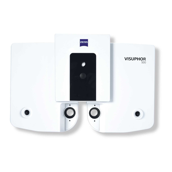
Page 24: Fig. 5 Visuphor 500 - Control And Functional Elements On Operator
6 Adjustment screw for forehead rest to set up the corneal vertex distance 7 Mount for the fixing rod of the near-point chart 8 Control lamp forehead rest 9 Forehead rest 10 Face rest 11 Examination window Fig. 5 VISUPHOR 500 - Control and functional elements on operator and patient side 000000-2075-933-GA-en-GB-230822... -
Page 25: Fig. 6 Junction Box - Control And Functional Elements
Description of the device Junction box 1 Power connection - appliance socket for connection to the power cable 2 Fuse compartment - slot for device fuses 3 Power switch (on/off) - toggle switch for switching the device on (I) and off (O) 4 Interface Com2 for connecting an autorefractor or digital lensmeter 5 Interface Com1 for connecting an autorefractor or digital lensmeter 6 Two-color status LED (green/blue) -
Page 26: Fig. 7 Near-Point Chart - Functional Elements
Description of the device Near-point chart 1 Mounting for fixing rod 2 Screw to fix the near-point chart to the fixing rod 3 Head section of near-point chart 4 Intermediate piece 5 Body of near-point chart 6 Turntable with 8 optotype cards (four each on front or rear of turntable) 7 Viewing window for selected optotype card 8 Field for showing card number Fig. - Page 27 This type of disruption could indicate improper or manipulated installation. Please contact ZEISS Service or your dealer if this device causes damage or disruption to other devices (contact information see reverse).
- Page 28 Installation WARNING - FIRE HAZARD The device is not suitable for operation in explosion risk areas (e.g. combustible mixture of anesthetic, cleaning or disinfecting agents with air, oxygen or nitrous oxide). The electrical installation must conform to IEC 60364-7-710. CAUTION - PROPERTY DAMAGE Do not store or use this device in damp rooms.
-
Page 29: Fig. 8 Interface Dimensions For Vertical Mounting Of The Phoropter
Installation Interfaces to mount the phoropter head 1 Fixing bolts Fig. 8 Interface dimensions for vertical mounting of the phoropter head 1 Assembly adapter ZDR10 2 Screws (M3x14 mm) and corresponding E-rings belonging to ZDR19 (see 3, Fig. 15) 3 Screws and corresponding E-rings for mounting set belonging to ZDR10 Fig. -
Page 30: Fig. 10 Interface Dimensions For Mounting The Phoropter Head With
Installation 1 Assembly adapter ZDR14 2 Screws and E-rings from mounting set 1 3 Screws and E-rings from mounting set 2 4 Screws not included in the package (use screws (M5) fitting to supporting arm) Fig. 10 Interface dimensions for mounting the phoropter head with the assembly adapter ZDR14 000000-2075-933-GA-en-GB-230822... -
Page 31: Fig. 11 Interface Dimensions For Mounting The Phoropter Head With
Installation 1 Assembly adapter ZDR15 2 Screws and E-rings from mounting set 1 3 Screws not included in the package (use screws (M4) fitting to supporting arm) Fig. 11 Interface dimensions for mounting the phoropter head with the assembly adapter ZDR15 000000-2075-933-GA-en-GB-230822... -
Page 32: Fig. 12 Interface Dimensions For Mounting The Phoropter Head With The Assembly Adapters Zdr14 And Zdr16
Installation 1 Assembly adapter ZDR16 2 Screws not included in the package (use screws (M4) fitting to supporting arm) 3 Assembly adapter ZDR14 4 Screws and E-rings from mounting set 1 5 Screws and E-rings from mounting set 2 Fig. 12 Interface dimensions for mounting the phoropter head with the assembly adapters ZDR14 and ZDR16 000000-2075-933-GA-en-GB-230822... -
Page 33: Fig. 13 Interface Dimensions For Mounting The Phoropter Head With
Installation 1 Assembly adapter ZDR17 2 Screws and E-rings from mounting set 1 Fig. 13 Interface dimensions for mounting the phoropter head with the assembly adapter ZDR17 For assembly, add corresponding drill holes and threads into the supporting arm. 000000-2075-933-GA-en-GB-230822... -
Page 34: Fig. 14 Interface Dimensions For Mounting The Phoropter Head With
Installation 1 Assembly adapter ZDR18 2 Spacers (3 pc.) 3 Screws not included in the package (use corresponding screws (M3)) 4 Screws not included in the package (use corresponding screws (M4)) 5 Screws not included in the package (use corresponding screws (M4)) Fig. -
Page 35: Fig. 15 Fixing Of Zdr19 And Zdr20 Adapter On Fixing Bolt Of
Installation 1 Assembly adapter ZDR19 or ZDR20 2 Fixing bolts 3 Screws M3x14 mm and E-rings D 5.4 mm to screw the adapter to the fixing bolt 4 Screws for vertical fixing of the phoropter head 5 Knurled screw Fig. 15 Fixing of ZDR19 and ZDR20 adapter on fixing bolt of phoropter 000000-2075-933-GA-en-GB-230822... -
Page 36: Fig. 16 Interface Dimensions For Mounting The Phoropter Head With
Installation 1 Mounting for fixing rod 2 Screw for horizontal fixing of phoropter head (use one of the screws from mounting set 3 depending on the thread) Fig. 16 Interface dimensions for mounting the phoropter head with the assembly adapter ZDR19 1 Mounting for fixing rod Fig. - Page 37 Installation Interfaces to connect external devices The following devices can be connected to the ports Com1 (5, Fig. 6) and Com2 (4, Fig. 6): VISULENS 500 Digital Lensmeter from software version v1.2.3 VISUREF 100 Autorefractometer/Keratometer from software version v2.1.7 Proceed as follows: •...
-
Page 38: Fig. 18 Interface To Visuscreen Control Unit
Installation • Close the unit again by slightly tilting the cover onto the retaining tabs of the housing, and then pressing the lower side inwards. • Retighten the knurled screw (1, Fig. 18). 1 Knurled screw 2 VISUSCREEN housing cover 3 Bluetooth/USB adapter 4 USB port 5 Antenna at junction box... - Page 39 Daily startup Daily startup WARNING - GENERAL HAZARD Prior to using the device, the user must ensure that it is in a good condition and fully functioning. Furthermore, the user must follow the instructions in the user manual. The following inspections must be carried out each working day prior to use: •...
- Page 40 Please keep the patient away from the device during the self-test. • First, turn the VISUPHOR 500 device on, then the VISUSCREEN control unit. • T o do so, use the power switch (3, Fig. 6) on the junction box.
-
Page 41: Operation Of The Device
Operation of the device Operation of the device CAUTION - PROPERTY DAMAGE Do not hit or drop the device. Impacts may damage the device and lead to a malfunction. Pay attention to ensure that the device does not become dirty, and do not expose it to any metallic dust or chips. - Page 42 Operation of the device Preparation of the device: • Leveling Check the horizontal mounting of the phoropter head using the spirit level (2, Fig. 5). If necessary use the leveling screw (3, Fig. 5) to align the head. • Cleaning Clean the face shield, the forehead rest and the examination window.
-
Page 43: Fig. 19 Set Up Near-Point Chart
Operation of the device 1 Intersection between the head piece and the scale foot 2 Mounting the near-point chart to the fixing rod 3 Moving the near-point chart to set up the distance from the eye 4 Turning the chart to select the front or rear 5 Turning the turntable to select the optotype card 6 Field for showing card number 7 Fixing rod with scale... - Page 44 Operation of the device Selection table for optotype card Card Description Number shown number on the examiner’s side Landolt rings Optotype sequence for visual acuity 0.1, 0.2, 0.25, 0.32 Optotype sequence for visual acuity 0.4, 0.5, 0.63, 0.8, 1.0 Grid Fan chart Vertical number series Horizontal number series...
-
Page 45: Fig. 20 Fold Up The Near-Point Chart And Fixing Rod
Operation of the device 1 Near-point chart (collapsible) 2 Joint to fold up the fixing rod. Fig. 20 Fold up the near-point chart and fixing rod Transferring data • T ake over the objective refraction data for the patient from FORUM, iCom or your practice management system into the control software. - Page 46 Operation of the device Positioning the patient • Ask your patient to sit down in front of the phoropter or bring the phoropter into position in front of the patient. The patient has to be sitting comfortably and lean his head onto the middle of the forehead rest (9, Fig.
-
Page 47: Fig. 21 Positioning The Patient And Setting Up The Cvd
Operation of the device 1 Control window 2 Adjusting screw to set the CVD 3 Reference line 4 Reference triangles 5 Vertex of the patient’s eye Fig. 21 Positioning the patient and setting up the CVD Perform examination When the PD data that have been set up are taken over into the control software, the illumination of the patient’s eyes ceases and the set-up for the objective refraction data (sphere, cylinder and axis) taken over from the PMS are used in place of the reticules. -
Page 48: Shutting Down
• Faults that cannot be remedied based on the information provided in this user manual. Label the instrument clearly as being out of service and report the problem to the ZEISS service (contact details see reverse). • Switch off the device at the power switch. ... -
Page 49: Maintenance And Care
The device may only be opened, put into operation, modified and repaired by the manufacturer’s customer service technicians or specialists expressly authorized in writing by Carl Zeiss Meditec. If in doubt, insist on seeing the written authorization or contact Carl Zeiss Meditec directly. -
Page 50: Replacing The Forehead Rest
Maintenance and care Replacing the forehead rest • Remove the forehead rest by pulling this away from the device. Avoid pushing the forehead rest up further than its stopping point. This could cause the holding bridges on the back of the forehead rest to break off. -
Page 51: Fig. 23 Inserting The Forehead Rest
Maintenance and care • T o insert the forehead rest (1, Fig. 23) place the holding bridges (2, Fig. 23) on the back of the forehead rest on the forehead rest insertion point on the device side (3, Fig. 23). 1 Forehead rest 2 Holding bridges 3 Mount for forehead rest... -
Page 52: Replacing The Face Rest
Maintenance and care Replacing the face rest • T o remove the face rest, press its lower edge up slightly and remove the face rest carefully as shown in Fig. 24. • T o insert the face rest, place this into position and let it go. Fig. -
Page 53: Replacing The Fuses
Maintenance and care Replacing the fuses WARNING - RISK OF ELECTRIC SHOCK The VISUPHOR 500 must be switched off and disconnected from the power supply before being cleaned or serviced. Before changing the fuses, disconnect the device from the power supply to prevent the risk of serious injury or death. -
Page 54: Maintenance
Maintenance and care • Remove the defective fuse (2, Fig. 25) from the fuse carrier (1, Fig. 25) and replace it with a new fuse. • Replace the fuse compartment (1, Fig. 25) and ensure the locking mechanism clicks in. Maintenance Care and cleaning WARNING - RISK OF ELECTRIC SHOCK... -
Page 55: Cleaning The Exterior Components
Maintenance and care Contaminated parts with which the patient has come into contact during the examination (forehead rest and face shield) should be cleaned with a disinfectant approved for the purpose. These parts are designed to be wiped down using mild cleaning agents and disinfectants such as suds, disinfectants based on quaternary ammonium compounds (0.2 %), glutoral (2 %) or isopropanol (60 %). -
Page 56: Safety Inspections
Maintenance and care Safety inspections Proceed as follows to perform a safety check of the device: • Check the protective earth conductor resistance. For this purpose, connect the device to the measuring instrument using the power cable. T o perform a measurement, press the measuring tip to the screw (measurement point) shown in Fig. -
Page 57: Replacement Of Components
Replacement of components Replacement of components If, after discussion with your dealer, it should be necessary to replace a device or a component, please proceed as follows: Document your structure carefully before removing a component. In so doing, pay particular attention to the specific points for your installation. Your records must enable you, together with the following notes, to recreate the current status of your installation. -
Page 58: Replacing The Phoropter Head
Replacement of components Replacing the phoropter head Disassembly • Remove the forehead rest, see chapter Replacing the forehead rest on page 44. • Remove the four screw covers ( Fig. 27). • Loosen and remove the four fixing screws (2, Fig. 27). •... -
Page 59: Mounting
Replacement of components • Loosen the two fixing screws (1, Fig. 28) for the connector cable. • Pull the connector cable off upwards (2, Fig. 28). In so doing, hold the cable directly at the plug. • Hold the phoropter head firmly during removal to prevent this from falling. -
Page 60: Replacing The Junction Box
• Connect all of the associated cables to the junction box and unfold the antenna (1, Fig. 29). After going live, it may also be necessary to update the system configuration (see “VISUSCREEN 100/500 - Subjective refraction with VISUPHOR 500“ user manual). 000000-2075-933-GA-en-GB-230822... -
Page 61: Optional Accessories
If the device has been modified, it must be tested and checked in order to ensure the safe operation of the device after its modification. Use only accessories and spare parts approved by Carl Zeiss Meditec. A current and complete list of accessories can be obtained from your retailer. 000000-2075-933-GA-en-GB-230822... -
Page 62: Technical Data
Technical data Technical data Dimensions (W x D x H) Digital Phoropter 361 mm x 108 mm x 280 mm Junction box 71 mm x 240 mm x 251 mm Weight 4.74 kg Digital Phoropter 1.88 kg Junction box Mains voltage 100 V to 240 V AC Line frequency 50/60 Hz... - Page 63 Technical data Setting range Spherical lenses -29.00 D to +26.75 D. -19.00 D to +16.75 D (when using a cross cylinder or a prism) (steps of 0.125 D) Toric lenses Cylinder power 0.00 D to 8.75 D (steps of 0.25 D) Cylinder axis 0°...
-
Page 64: Electromagnetic Compatibility
Portable and mobile RF communications equipment may affect the device. When operating radio devices or components for radio transmission, observe a distance of at least 30 cm to all parts of ZEISS VISUPHOR 500, including cables specified by the manufacturer. Otherwise, a malfunction or reduced performance of the device is to be expected. - Page 65 Electromagnetic compatibility CAUTION – RISK OF ELECTROMAGNETIC RADIATION The ZEISS VISUPHOR 500 may not be placed next to or stacked together with other equipment, except in the device configurations described in this user manual. If operation close to or with other devices is necessary, the ZEISS VISUPHOR 500 must be closely observed to monitor its proper functioning in this configuration.
-
Page 66: Emission
Electromagnetic compatibility Emission Emission Standard Compliance Conducted emission CISPR 11 Group 1 Radiated emission CISPR 11 Class B Harmonic emissions IEC 61000-3-2 Class A Voltage fluctuations/flicker emissions IEC 61000-3-3 Complies 000000-2075-933-GA-en-GB-230822... -
Page 67: Immunity
Electromagnetic compatibility Immunity Phenomenon Standard Test level ±8 kV contact IEC 61000-4-2 Electrostatic discharge ±2 kV, ±4 kV, ±8 kV, ±15 kV air (housing, connections) 10 V/m Radiated RF EM fields IEC 61000-4-3 80 MHz to 2.7 GHz 80 % AM at 1 kHz ±2 kV, 100 kHz repetition rate (power cable) Electrical fast transients/bursts... - Page 68 Electromagnetic compatibility Phenomenon Standard Test frequency Radio service Immunity test (MHz) level (V/m) TETRA 400 GMRS 460, FRS 460 LTE Band 13,17 GSM 800/900, TETRA 800, iDEN 820, Immunity to radiated CDMA 850, radio frequencies, LTE Band 5 caused by wireless IEC 61000-4-3 communications 1720...
-
Page 69: Abbreviations/Glossary
Abbreviations/Glossary Abbreviations/Glossary Automatic refractometer / keratometer CISPR Comité international spécial des perturbations radioélectriques (Special International Committee on Radio Interference) Vertex distance Diopters Decibel isotropic Decibel relative to 1 milliwatt Deutsches Institut für Normung (German standards association) European Community Electromagnetic compatibility Europäische Norm (European standard) Electrostatic discharge ESDS... -
Page 70: Figures
Fig. 2 Package check list of assembly adapters and corresponding mounting sets................Fig. 3 Warning and information labels on the VISUPHOR 500....10 Fig. 4 Warning and information labels on the junction box....13 Fig. 5 VISUPHOR 500 - Control and functional elements on operator and patient side................. -
Page 71: Index
Index Index Abbreviations .................... Accessories, optional ................. Assembly....................Care......................Classification of the device................. Cleaning....................Contraindications ..................Daily startup....................Description of the device................Disposal..................... Electromagnetic compatibility..............External labels ................... Figures ...................... Functional description ................Fuses......................Glossary ....................Installation ....................Intended use ....................Intended user profile ................... - Page 72 Index Operation of the device ................Optotype charts..................Package check list..................Performance specifications..............Safety inspections ..................Service life ....................Shutting down..................Side effects....................Switching off .................... Switching on................... Symbols..................... Technical data ..................Troubleshooting..................Unpacking ....................000000-2075-933-GA-en-GB-230822...
- Page 73 Index 000000-2075-933-GA-en-GB-230822...
- Page 74 Index Carl Zeiss Meditec AG Goeschwitzer Str. 51-52 07745 Jena Germany Telephone: +49 3641 220 333 000000-2075-933-GA-en- Fax: +49 3641 220 112 GB-230822 VISUPHOR 500 Email: info.meditec@zeiss.com Internet: www.zeiss.com/med Subject to change 000000-2075-933-GA-en-GB-230822...
- Page 76 Your contact The address of your contact person may be found in a separate document or on a label attached to the device. Carl Zeiss Meditec AG Goeschwitzer Str. 51-52 07745 Jena Germany Telephone: +49 3641 220 333 Fax: +49 3641 220 112 Email: info.meditec@zeiss.com...
Need help?
Do you have a question about the VISUPHOR 500 and is the answer not in the manual?
Questions and answers