Table of Contents
Advertisement
Quick Links
Z690 A ELITE STEALTH
(Z690 AORUS ELITE STEALTH)
User's Manual
Rev. 1001
12ME-Z69ELTS-1001R
For more product details, please visit GIGABYTE's website.
To reduce the impacts on global warming, the packaging materials of this product
are recyclable and reusable. GIGABYTE works with you to protect the environment.
Advertisement
Table of Contents

Related Manuals for Gigabyte Z690 AORUS ELITE STEALTH


Summary of Contents for Gigabyte Z690 AORUS ELITE STEALTH
- Page 1 (Z690 AORUS ELITE STEALTH) User's Manual Rev. 1001 12ME-Z69ELTS-1001R For more product details, please visit GIGABYTE's website. To reduce the impacts on global warming, the packaging materials of this product are recyclable and reusable. GIGABYTE works with you to protect the environment.
- Page 2 The trademarks mentioned in this manual are legally registered to their respective owners. Disclaimer Information in this manual is protected by copyright laws and is the property of GIGABYTE. Changes to the specications and eatures in this manual may be made by GIGABYTE without prior notice.
-
Page 3: Table Of Contents
Table of Contents Chapter 1 Product Introduction..................4 Motherboard Layout..................4 Motherboard Block Diagram ................6 Chapter 2 Hardware Installation ..................7 Installation Precautions ..................7 Product Specications..................8 Installing the CPU and CPU Cooler ............... 11 Installing the Memory ..................14 Installing an Expansion Card ................. -
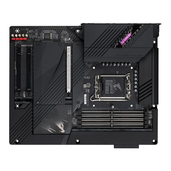
Page 4: Chapter 1 Product Introduction
Chapter 1 Product Introduction Motherboard Layout Front View USB20 USB 2.0 Hub LGA1700 U32G2 DP_HDMI20 U320G U32_LAN AUDIO PCIEX16 Realtek ® 2.5GbE LAN Intel ® Z690 ® Super I/O CODEC PCIEX4_1 M_BIOS USB 2.0 Hub PCIEX4_2 Temperature sensor - 4 -... - Page 5 Back View CPU_OPT ATX_12V_2X2 ATX_12V_2X4 LED_C2 D_LED2 CPU_FAN THB_C2 THB_C1 SYS_FAN2 CLR_CMOS F_PANEL SYS_FAN3 QFLASH_PLUS F_USB2 D_LED1 SYS_FAN4_PUMP SYS_FAN1 F_USB1 LED_C1 F_AUDIO - 5 -...
-
Page 6: Motherboard Block Diagram
Motherboard Block Diagram PCI Express 5.0 Bus CPU CLK+/- (80~800 MHz) DDR5 4800/4000 MHz LGA1700 CPU PCI Express 4.0 Bus DisplayPort HDMI 2.0 1 M.2 Socket 3 (M2A_CPU) 4 SATA 6Gb/s (SATA3 4~7) BIOS PCI Express 4.0 Bus eSPI ® Super I/O Switch 2 M.2 Socket 3... -
Page 7: Chapter 2 Hardware Installation
Chapter 2 Hardware Installation Installation Precautions The motherboard contains numerous delicate electronic circuits and components which can become damaged as a result of electrostatic discharge (ESD). Prior to installation, carefully read the user's manual and follow these procedures: • Prior to installation, make sure the chassis is suitable for the motherboard. •... -
Page 8: Product SpeciCations
Š Support for non-ECC Un-buffered DIMM 1Rx8/2Rx8/1Rx16 memory modules Š Support for Extreme Memory Prole (XMP) memory modules (Go to GIGABYTE's website for the latest supported memory speeds and memory modules.) Onboard Š Integrated Graphics Processor-Intel HD Graphics support: ®... - Page 9 Storage Interface Š CPU: 1 x M.2 connector (Socket 3, M key, type 2260/2280/22110 PCIe 4.0 x4/x2 SSD support) (M2A_CPU) Chipset: Š 2 x M.2 connectors (Socket 3, M key, type 2260/2280/22110 PCIe 4.0 x4/x2 SSD support) (M2P_SB/M2Q_SB) 1 x M.2 connector (Socket 3, M key, type 2260/2280/22110 SATA and PCIe 4.0 x4/x2 SSD support) (M2M_SB) 6 x SATA 6Gb/s connectors Support for RAID 0, RAID 1, RAID 5, and RAID 10...
- Page 10 Š Š ATX Form Factor; 30.5cm x 24.4cm Form Factor * GIGABYTE reserves the right to make any changes to the product specications and product-related information without prior notice. Please visit GIGABYTE's website for Please visit the Support\Utility List support lists of CPU, memory modules, page on GIGABYTE's website to SSDs, and M.2 devices.
-
Page 11: Installing The Cpu And Cpu Cooler
Read the following guidelines before you begin to install the CPU: • Make sure that the motherboard supports the CPU. (Go to GIGABYTE's website for the latest CPU support list.) • Always turn off the computer and unplug the power cord from the power outlet before installing the CPU to prevent hardware damage. - Page 12 B. Installing the CPU Follow the steps below to correctly install the CPU into the motherboard CPU socket. Finger Tab jGently press the CPU socket lever handle down and away from the socket. kCompletely lift up the CPU socket lock- ing lever.
- Page 13 C. Installing the CPU Cooler Be sure to install the CPU cooler after installing the CPU. (Actual installation process may differ depending the CPU cooler to be used. Refer to the user's manual for your CPU cooler.) Apply an even and thin layer of thermal grease on the surface of the installed CPU.
-
Page 14: Installing The Memory
Read the following guidelines before you begin to install the memory: • Make sure that the motherboard supports the memory. It is recommended that memory of the same capacity, brand, speed, and chips be used. (Go to GIGABYTE's website for the latest supported memory speeds and memory modules.) •... -
Page 15: Installing An Expansion Card
Installing an Expansion Card Read the following guidelines before you begin to install an expansion card: • Make sure the motherboard supports the expansion card. Carefully read the manual that came with your expansion card. • Always turn off the computer and unplug the power cord from the power outlet before installing an expansion card to prevent hardware damage. -
Page 16: Back Panel Connectors
1 Gbps data rate No data transmission or receiving is occurring 100 Mbps data rate LAN Port (Note) To enable the Q-Flash Plus function, please navigate to the "Unique Features" page of GIGABYTE's website for more information. - 16 -... - Page 17 • When removing the cable, pull it straight out from the connector. Do not rock it side to side to prevent an electrical short inside the cable connector. Please visit GIGABYTE's website or details on conguring the audio sotware. - 17 -...
-
Page 18: Internal Connectors
Internal Connectors 8 3 6 ATX_12V_2X2/ATX_12V_2X4 F_PANEL F_AUDIO CPU_FAN F_U32C SYS_FAN1/2/3 F_U32 SYS_FAN4_PUMP F_USB1/F_USB2 CPU_OPT THB_C1/THB_C2 LED_C1/LED_C2 QFLASH_PLUS D_LED1/D_LED2 CLR_CMOS SATA3 2/3/4/5/6/7 M2A_CPU/M2P_SB/M2Q_SB/M2M_SB Read the following guidelines before connecting external devices: • First make sure your devices are compliant with the connectors you wish to connect. •... - Page 19 1/2) ATX_12V_2X2/ATX_12V_2X4/ATX (2x2, 2x4, 12V Power Connectors and 2x12 Main Power Connector) With the use of the power connector, the power supply can supply enough stable power to all the components on the motherboard. Beore connecting the power connector, rst make sure the power supply is turned off and all devices are properly installed.
- Page 20 For optimum heat dissipation, it is recommended that a system fan be installed inside the chassis. The header also provides speed control for a water cooling pump. Please navigate to the "BIOS Setup" page of GIGABYTE's website and search for "Smart Fan 6" for more information. Pin No. Denition...
- Page 21 Incorrect connection may lead to the damage of the LED strip. For how to turn on/off the lights of the LED strip, please navigate to the "Unique Features" page of GIGABYTE's website. Before installing the devices, be sure to turn off the devices and your computer. Unplug the power cord from the power outlet to prevent damage to the devices.
- Page 22 1.5Gb/s standard. Each SATA connector supports a single SATA device. The Intel Chipset supports RAID 0, ® RAID 1, RAID 5, and RAID 10. Please navigate to the "Conguring a RAID Set" page o GIGABYTE's website or instructions on conguring a RAID array. Pin No. Denition SATA3 To enable hot-plugging for the SATA ports, please navigate to the "BIOS Setup"...
- Page 23 M.2 SSDs is supported by the M.2 socket you want to use. Please note that an M.2 PCIe SSD cannot be used to create a RAID set either with an M.2 SATA SSD or a SATA hard drive. Please navigate to the "Conguring a RAID Set" page o GIGABYTE's website or instructions on conguring a RAID array. M2A_CPU...
- Page 24 Installation Notices for the M.2 and SATA Connectors: The availability of the SATA connectors may be affected by the type of device installed in the M.2 sockets. The M2M_SB connector shares bandwidth with the SATA3 2, 3 connector. Refer to the following table for details. •...
- Page 25 Connects to the power switch on the chassis ront panel. You may congure the way to turn o your system using the power switch (please navigate to the "BIOS Setup" page of GIGABYTE's website and search for "Soft-Off by PWR-BTTN" for more information).
- Page 26 12) F_AUDIO (Front Panel Audio Header) The ront panel audio header supports High Denition audio (HD). You may connect your chassis ront panel audio module to this header. Make sure the wire assignments of the module connector match the pin assignments of the motherboard header. Incorrect connection between the module connector and the motherboard header will make the device unable to work or even damage it.
- Page 27 14) F_U32 (USB 3.2 Gen 1 Header) The header conorms to USB 3.2 Gen 1 and USB 2.0 specication and can provide two USB ports. For purchasing the optional 3.5" front panel that provides two USB 3.2 Gen 1 ports, please contact the local dealer.
- Page 28 16) THB_C1/THB_C2 (Thunderbolt Add-in Card Connectors) ™ The connectors are used to connect to a GIGABYTE Thunderbolt add-in card. ™ THB_C2 THB_C1 Supports a Thunderbolt add-in card. ™ 17) QFLASH_PLUS (Q-Flash Plus Button) Q-Flash Plus allows you to update the BIOS when your system is off (S5 shutdown state). Save the latest BIOS on a USB thumb drive and plug it into the dedicated port, and then you can now fash the BIOS automatically by simply pressing the Q-Flash Plus button.
- Page 29 CMOS values. • After system restart, go to BIOS Setup to load factory defaults (select Load Optimized Defaults) or manually congure the BIOS settings (please navigate to the "BIOS Setup" page o GIGABYTE's website for more information). 19) BAT (Battery) The battery provides power to keep the values (such as BIOS congurations, date, and time inormation)
-
Page 30: Chapter 3 Bios Setup
If this occurs, try to clear the CMOS values and reset the board to default values. • Reer to the introductions o the battery/clear CMOS jumper in Chapter 2 or navigate to the "BIOS Setup" page of GIGABYTE's website and search for "Load Optimized Defaults" for how to clear the CMOS values. - Page 31 Startup Screen: The following startup Logo screen will appear when the computer boots. Function Keys Function Keys: <DEL>: BIOS SETUP\Q-FLASH Press the <Delete> key to enter BIOS Setup or to access the Q-Flash utility in BIOS Setup. <F12>: BOOT MENU Boot Menu allows you to set the rst boot device without entering BIOS Setup.
-
Page 32: Chapter 4 Installing The Operating System And Drivers
rst during the OS installation process. Reer to the steps below: Step 1: Go to GIGABYTE's website, browse to the motherboard model's web page, download the Intel SATA Preinstall driver le on the Support\Download\SATA RAID/AHCI page, unzip the le and copy the les to your USB thumb drive. -
Page 33: Drivers Installation
After you install the operating system, a dialog box will appear on the bottom-right corner of the desktop asking if you want to download and install the drivers and GIGABYTE applications via APP Center. Click Install to proceed with the installation. (In BIOS Setup, make sure Settings\IO Ports\APP Center Download & Install Conguration\APP Center Download &... -
Page 34: Chapter 5 Appendix
• An M.2 PCIe SSD cannot be used to set up a RAID set either with an M.2 SATA SSD or a SATA hard drive. • Refer to "Internal Connectors," for the installation notices for the M.2 and SATA connectors. Please visit GIGABYTE's website or details on conguring a RAID array. - 34 -... -
Page 35: Regulatory Notices
47 CFR § 2.1077 Compliance Information Product Name: Motherboard Trade Name: GIGABYTE Model Number: Z690 A ELITE STEALTH (Z690 AORUS ELITE STEALTH) Responsible Party – U.S. Contact Information: G.B.T. Inc. Address: 17358 Railroad street, City Of Industry, CA91748 Tel.: 1-626-854-9338 Internet contact information: https://www.gigabyte.com... -
Page 36: Contact Us
Contact Us GIGA-BYTE TECHNOLOGY CO., LTD. Address: No.6, Baoqiang Rd., Xindian Dist., New Taipei City 231, Taiwan TEL: +886-2-8912-4000, FAX: +886-2-8912-4005 Tech. and Non-Tech. Support (Sales/Marketing) : https://esupport.gigabyte.com WEB address (English): https://www.gigabyte.com WEB address (Chinese): https://www.gigabyte.com/tw GIGABYTE eSupport • To submit a technical or non-technical (Sales/Marketing) question, please link to: https://esupport.gigabyte.com...
Need help?
Do you have a question about the Z690 AORUS ELITE STEALTH and is the answer not in the manual?
Questions and answers