Table of Contents
Advertisement
Advertisement
Table of Contents

Summary of Contents for Alimak ALC II
- Page 1 ALIMAK ALC II User's manual Original instructions Access anytime, anywhere...
- Page 3 Applicable for ALC II software version 3.71 and later versions ONLY! This manual is only applicable if the manufacturing number indicated below corresponds to the manufacturing number stamped on the identification sign of the equipment. Where there is a conflict contact your ALIMAK representative. YOUR HOIST HAS: Art.
- Page 4 Specifications of products and equipment shown herein are subject to change without notice. Copyright © 2018 Alimak Group Sweden AB. All rights reserved. Alimak and Scando are registered trademarks of Alimak Group Sweden AB. Alimak Group Sweden AB is ISO 9001, 14001, and OHSAS 18001 certified.
-
Page 5: Table Of Contents
ALIMAK LIFT CONTROL, ALC II Alimak Lift Control, ALC II ......Semi-automatic control system ......Collective control system ........ALC II additional features ........ Factory calibration ..........Stop / retardation distances ......A 10 System set-up ............A 12 ALC II diagnose mode ........ - Page 6 Text and illustrations by Mats Holmlund & Håkan Lindström Copyright © 2018 Alimak Group Sweden AB. All rights reserved.
-
Page 7: Alimak Lift Control, Alc Ii
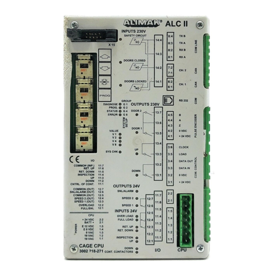
Alimak Lift Control, ALC II Alimak lift control, ALC II, is the name of Alimak’s modular Pulse encoder controller. The ALC system consists of a microprocessor based controller, equipped with a high speed pulse counter input and a pulse encoder. The position of the lift / hoist is determined by counting impulses generated by the pulse encoder attached to the drive unit. - Page 8 This page is intentionally left blank...
- Page 9 Fuses There are 4 fuses on the CPU-unit: 2 fuses (3.15A) are for the 2 x 19VAC input to the ALC II. 1 fuse (4A) is for the 24VDC output. 1 fuse (1.25A) is for the 12VDC output. Control systems...
-
Page 10: Semi-Automatic Control System
This system receives all destination orders from inside the car, as Next Landing button immediately before the hoist starts, to achieve well as calls from the landings. The information is memo-rized normal operation speed. and processed within the system. ALIMAK 34817 - 1 /04... - Page 11 CPU inside the base panel. The information is transmitted from the base CPU to the car CPU (main unit) on a two wire communication circuit in the trailing cable. Indication lamp ’’Out of service’’ for construction hoists only ALIMAK 34818 - 0 /01...
-
Page 12: Alc Ii Additional Features
ALC II additional features Auto return, Authorized drive, Flood alarm and High wind speed are examples of features available in the ALC II system. These functions can be chosen with the system’s normal set-up procedures (page A 12 – A 15). - Page 13 ID06 To meet this demand in order to prevent unauthorized persons to drive Alimak products. A external function with only a digital input on ALCII this prevents personnel to be able to call or run the lift. It is controlled from Input 12:1 at Car Exp.
-
Page 14: Factory Calibration
– The LEDs V1 and V2 are flashing rapidly indicating that the system is lack of speed information. – Reconnect the battery. – In case of DOL system go to page A10, and for VFC system go to A11. ALIMAK 34819/1 - 1 /10... - Page 15 The display shows: (no landings are programmed into the system): System with dual display. System with single display. – Reconnect the battery. Calibration drive is performed from inside the car, starting from the bottom landing. ALIMAK 34819/2 - 1 /04...
-
Page 16: Stop / Retardation Distances
New system set-up and system calibration must be done if car CPU is replaced. Keep the Up/Down button depressed during the entire drive sequence – if the hold to run feature is chosen. ALIMAK 34820 - 1 /05... - Page 17 New system set-up and system calibration must be done if car CPU is replaced. Keep the Up/Down button depressed during the entire drive sequence – if the hold to run feature is chosen. ALIMAK 34184 - 1/05...
-
Page 18: System Set-Up
See collection of illustrative examples at the end of this manual. NOTE! All values in GROUP 15 must be preset before the factory calibration drive is performed. After running the factory calibration drive the GROUP 15 will be locked for further changes. ALIMAK 34822 - 1 /05... - Page 19 Car CPU (main unit) ALIMAK 34823 - 1 /03...
- Page 20 VALUE 1 level 16 to be added to level 2 (previous • group 12 above) • • GROUP 10 o VALUE 3 V1 + V2 = 3 = level 18 • • (level 3 chosen) • ALIMAK 34906 - 1/09...
- Page 21 Ex. proof lift • • • • • SYS.CAL OK. * = means varaible, LED ON or LED OFF. ** If 7 is choosen – desired time can be selected ALIMAK 34907 - 1/12 by the VirutualPanal service tool.
- Page 22 If V1 + V2 flash rapidly out of syn, the system calibration has not been performed. Note 2 If internal voltage drops under 20VDC, an f8 alarm will be shown as indication, but it will not stop the lift/hoist. ALIMAK 35046 - 1 /11...
-
Page 23: Alc Ii Diagnose Mode
ALC II Diagnose mode To enter diagnose mode: – Disconnect the battery. – Turn main power switch in OFF position. – Push and hold the SNL button. – Turn main power switch in ON position. – When DIAGNOSE is on – release the SNL button. - Page 24 See examples below. A Language selection A ALC Error Message A Current landing A ALC Error Message Direction Open door C Destinated landing C Error symbol (Overload) D Weight ALIMAK 34184 A - 1/10...
-
Page 25: Information And Fault Indications On Displays A
Information and fault indications on displays Fault indications A hoist / lift equipped with the ALIMAK ALC control system and landing level display on the lift electrical panel has access to a fault indication system. Faults indicated at the display are the following:... -
Page 26: Programming Of Dol Operated Lifts
CD flashes on the display for the single system. All the landings have now been deleted and the lift returns to the calibration mode. Calibration drive, CD The intention with the calibration drive is to pick up reference level. ALIMAK 34827 - 1 /09... - Page 27 (”Ref. down” LED goes out). The display shows: The reference level is now programmed into the system. The system is now back into normal mode, but no landings are programmed into the system. See page Programming of landings. ALIMAK 34828 - 1 /04...
- Page 28 Calibration drive from inside of the car when lift is located permanent lifts somewhere above the bottom landing: The displays show: (if the number of programmed landings is 5). CD and 5 flash alternately on the display for the single system. ALIMAK 34829 - 1 /04...
- Page 29 – Press the Call button and the lift will go down to the bottom and stop. The reference level is now programmed into the system. The system is now back into normal mode. Direct the lift to the desired landing. ALIMAK 34830 - 1 /04...
-
Page 30: Programming Of Vfc Operated Lifts
Applicable for ALC II software version 3.29 and later Programming of VFC operated lifts Calibration drive (CD) and deletion of all landings. Before the programming of landings can start, the reference point has to be established and since the lift could have been used before, all previous landings that might be programmed into the system, must be deleted. - Page 31 The display shows: The reference level is now programmed into the system. The system is now back into normal mode, but no landings are programmed into the system. See page Programming of landings. ALIMAK 335051 - 1/09...
- Page 32 Applicable for ALC II software version 3.29 and later Landings ARE stored into the system Calibration drive from inside of the car when lift is located at bottom landing: The displays show: (if 5 landings are programmed into the system).
- Page 33 The lift continues in crawling speed down to the bottom landing. The reference level is now programmed into the system. The system is now back into normal mode. Direct the lift to the desired landing. ALIMAK 335053 - 1/09...
- Page 34 Open suitable door for the landing in question. (If not, the landing will be stored as a closed landing). The Prog. LED goes out. The second landing level is then programmed into the system and the systemt returns to normal operation. ALIMAK 34831 - 1 /04...
- Page 35 Prog. LED goes out. The top landing level is now deleted and the system returns to normal operation. The display shows: 4 lights up on the display for the single system. ALIMAK 34832 - 1 /04...
- Page 36 When intended floor level indication is achieved – close the door and the new floor level indication will be stored. – Press the Prog. button on the car CPU inside the main panel to change Image bank. ALIMAK 34833 - 1 /04...
- Page 37 When erasing all floors you must be on lowest floor. Remember that programming of minus floor is not the same as changing floor indication. To set minus 2 (–2) with keyboard, press 0 and 2. ALIMAK 34834 - 1 /04...
-
Page 38: Landing Extension Box For Landings Above
The displays show (if the lift is on landing 4): 4 lights up on the display for the single system. Programming of passing through landings Two push-button boxes at the same landing ALIMAK 34835 - 1 /04... - Page 39 Open suitable doors for the landings in question. The display shows: 0 lights up on the display for the single system. NOTE! If you have to adjust the landing levels the entire procedure must be repeated. ALIMAK 34836 -1 /05...
- Page 40 The Prog. LED goes out. The first landing level is then programmed into the system and the system returns to normal operation. Note: do not operate the lift from this position. ALIMAK 34837 - 1 /04...
- Page 41 Permanent Lift Press 0. The 1st car door will be unlocked. No car movement will appear. The display shows: Press 1. The 2nd car door will be unlocked. No car movement will appear. The display shows: ALIMAK 34838 - 1 /04...
- Page 42 The first landing level is then programmed into the system and the system returns to normal operation. Note: do not operate the lift from this position. The display shows: 0 lights up on the display for the single system. ALIMAK 34839 - 1 /04...
- Page 43 Open suitable door for the landing in question. The display shows: 0 lights up on the display for the single system. NOTE! If you have to adjust the landing levels the entire procedure must be repeated. ALIMAK 34840 - 1 /04...
- Page 44 – Push the Stop Next Landing button on the car CPU. The system will unlock the doors one by one. Open suitable door for the landing in question (if not, the landing will be stored as a closed landing). The Prog. Led goes out. ALIMAK 35009 - 1/12...
- Page 45 – It is not possible to program additional landings above the movable top landing. – Ensure that the normal and final limit cams are properly installed above he top landing before leaving the machine to the end user. ALIMAK 35010 - 1/05...
-
Page 46: Alc For Construction Hoistsa
ALC II for Construction Hoists Control station in the car Semi-automatic control: The control station front includes as standard: – Joystick for Up and Down and an additional Stop Next Landing push-button (The Stop Next Landing button is illuminated). – A 2-digit display, showing current landing, fault indication and information. - Page 47 On the inside of the control panel: – Push-button on the car CPU. – Norm. / Insp. selector switch. Top of car control: Top of car control consists of: – Up and Down push-button. – An Emergency stop push-button. ALIMAK 34842 - 1 /01...
- Page 48 CPU inside the base panel. The information transmits from the base CPU to the car CPU (main unit) on a two wire communication circuit in the trailing- (hybrid) cable. ALIMAK 34843 - 1 /01...
- Page 49 Everything OK No light: Base-panel switched off Flashing (slow): CAN-communication to B-panel not working. Flashing (fast): No landing call boxes connected to the Extension box or malfunction on landing call boxes. ** B-panel + 31 Landing boxes. ALIMAK 34184 - 1/07...
-
Page 51: Installation
5. Connect the landing control cable to the base panel and to each landing unit in accordance with the wiring diagram. 6. The system is now ready for programming. Plug for connection of the landing circuit to the B-panel ALIMAK 34824 - 1 /01... -
Page 52: Group Control
Group control for less than 20 pcs. landings Single tower with a dual car installation Alimak prefab. push button box and connection cables 1st B-panel 2nd B-panel Twin towers with a dual car installation each Bus divider CAN bus communiction cable ALIMAK 35042 - 1 /07... - Page 53 P/N 9070745-601 CAN bus communiction cable length 2.0 m ( 6.5 ft.) P/N 9070745-702 length 7.0 m ( 23 ft.) – ’’ – P/N 9070745-707 – ’’ – length 15.0 m ( 49 ft.) P/N 9070745-715 ALIMAK 35043 - 1 /07...
- Page 54 32 above level 32 Additional power Additional power box for landings box for landings above level 20 above level 20 Bus divider Bus divider Bus divider Bus divider CAN bus communiction cable ALIMAK 35044 - 1 /07...
- Page 55 Landing extension box for landings above level 32 Additional power box for landings above level 20 Bus divider Bus divider Bus divider Bus divider Bus divider Bus divider CAN bus communiction cable CAN bus communiction cable ALIMAK 35045 - 1 /07...
-
Page 56: Operation
8 just passing landing 5 and a stop at landing 6 is desired. The display shows: Press the Stop Next Landing key and the display shows: The hoist will now first stop at landing 6 and then on landing 8. ALIMAK 34845 - 1 /01... - Page 57 When the car approaches the desired landing, press the key ”Stop Next Landing” and the car will then stop automatically at the landing. After approximately 8 seconds on a landing the system is ready for a new destination. ALIMAK 34846 - 1 /01...
-
Page 58: Alc Ii For Permanent Liftsa
ALC II for Permanent Lifts Push-buttons and display inside car Collective control: The control station front includes as standard: – Push-buttons for up to 16 landing levels. – One 2-digit display showing current landing and fault indication and information. – An alarm push-button. -
Page 59: Operation
The lift is located on the 4th landing and the display shows: outside the el-panel. Landing 8 is desired, press button 8 and the display shows: When the lift arrives to the landing. Whenever additional destinations are required, press the desired buttons. ALIMAK 34184 - 1/08... - Page 60 ALC II TROUBLE SHOOTING Switch on the main switch on the Step into the Go to the desired hoist’s base panel. Usually built hoist car and landing. on the safety enclosure. close the gates. The hoist does not The hoist starts FROM LANDING: start.
- Page 62 Pictures are illustrative only and do not necessarily show the configuration of products on the market at a given point in time. Products must be used in conformity with safe practice and applicable statutes, regulations, codes and ordinances. Specifications of products and equipment shown herein are subject to change without notice. Copyright © 2018 Alimak Group AB. All rights reserved. Alimak and Scando...
Need help?
Do you have a question about the ALC II and is the answer not in the manual?
Questions and answers