Table of Contents
Advertisement
Read this "Basic Guide" and keep it handy for future reference.
Basic Guide
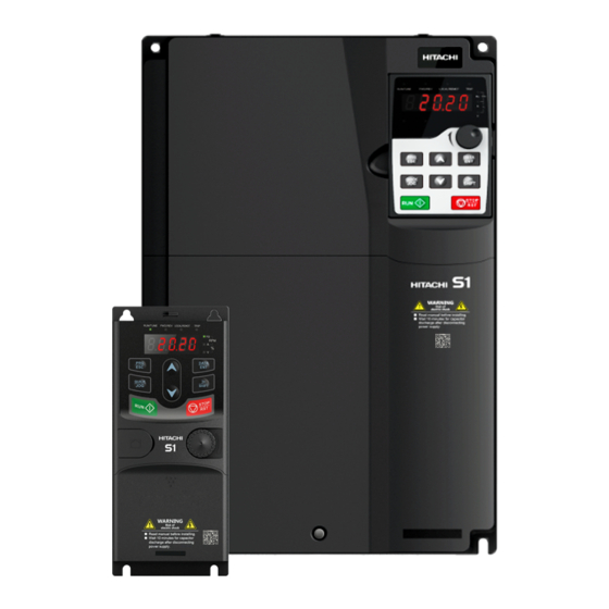
HITACHI S1 Series Inverter
Preface
Contents
Chapter 1: Safety precautions
S1
Chapter 2: Quick startup
Chapter 3: Product overview
Chapter 4: Installation Guide
Chapter 5: Basic operation instructions
Chapter 6: Function parameter list
Chapter 7: Troubleshooting
Chapter 8: Maintenance and hardware fault
Chapter 9: Communication protocol
Chapter 10: Technical data
Chapter 11: Dimension drawings
Chapter 12: Optional peripheral accessories
Chapter 13: STO function description
Chapter 14: Further information
If you have any inquiry or problem,
Refer to Chapter 7 Troubleshooting
or
Contact to the Technical Inquiry Service
for Inverter.
When contacting us, please mention
the below reference number.
BG-S1-05/20EN
diagnosis
Advertisement
Table of Contents

Related Manuals for Hitachi S1 Series


Summary of Contents for Hitachi S1 Series
- Page 1 Read this “Basic Guide” and keep it handy for future reference. Preface Contents Basic Guide Chapter 1: Safety precautions HITACHI S1 Series Inverter Chapter 2: Quick startup Chapter 3: Product overview Chapter 4: Installation Guide Chapter 5: Basic operation instructions...
- Page 2 ■ This document presents installation wiring, parameter setup, fault diagnosis and trouble shooting, and precautions related to daily maintenance. Read through this document carefully before installation to ensure S1 series inverter is installed and operated in a proper manner to make a correct use of its excellent performance and powerful functions.
-
Page 3: Table Of Contents
S1 series standard inverter Contents Preface ............................i Contents ............................ii Chapter 1 Safety precautions ......................1 1.1 What this chapter contains ....................1 1.2 Safety definition ........................1 1.3 Warning symbols ......................... 1 1.4 Safety guidelines ......................... 2 Chapter 2 Quick startup ........................ 5 2.1 What this chapter contains .................... - Page 4 S1 series standard inverter 7.2 Indications of alarms and faults ..................156 7.3 Fault reset ........................156 7.4 Fault history ........................156 7.5 Inverter faults and solutions ..................... 156 7.6 Analysis on common faults ....................161 7.7 Countermeasures on common interference ..............168 Chapter 8 Maintenance and hardware fault diagnosis .............
- Page 5 13.2 STO channel delay description ..................228 13.3 STO function installation checklist ................. 228 Chapter 14 Further information ....................229 14.1 Product and service queries ..................229 14.2 Feedback on HITACHI inverter manuals ................ 229 14.3 Documents on the Internet .................... 229...
-
Page 6: Chapter 1 Safety Precautions
S1 series standard inverter Chapter 1 Safety precautions 1.1 What this chapter contains Read this manual carefully and follow all safety precautions before moving, installing, operating and servicing the inverter. If these safety precautions are ignored, physical injury or death may occur, or damage may occur to the equipment. -
Page 7: Safety Guidelines
S1 series standard inverter Symbols Name Instruction Abbreviation off to prevent electric shock Read Read the operation manual before manual operating on the equipment Procedures taken to ensure proper Note Note Note operation 1.4 Safety guidelines Only trained and qualified electricians are allowed to carry out related operations. - Page 8 S1 series standard inverter Installation site should be away from children and other public places; The inverter cannot meet the requirements of low voltage protection in IEC61800-5-1 if the altitude of installation site is above 2000m; The inverter should be used in proper environment (see chapter 4.2.1 Installation environment for details);...
- Page 9 S1 series standard inverter Note: Use proper torque to tighten the screws. Keep the inverter and its parts and components away from combustible materials during maintenance and component replacement. Do not carry out insulation voltage-endurance test on the inverter, or measure the control circuits of the inverter with megameter.
-
Page 10: Chapter 2 Quick Startup
If not, contact local dealers or HITACHI offices. 5. Check whether the accessories (including user's manual, control keypad and extension card units) inside the packing box are complete. If not, contact local dealers or HITACHI offices. -
Page 11: Installation Confirmation
S1 series standard inverter Note: For cabinet-type inverter, its ambient temperature is the air temperature inside the cabinet. 3. Check whether the altitude of the application site exceeds 1000m, if yes, derate 1% for every additional 100 m. 4. Check whether the humidity of application site exceeds 90%, if yes, check whether condensation occurred, if condensation does exist, take additional protective measures. - Page 12 S1 series standard inverter 3. Adjust the acceleration and deceleration time based on actual working conditions of the load. 4. Jogging to carry out device commissioning. Check whether the motor running direction is consistent with the direction required, if no, it is recommended to change the motor running direction by exchanging the motor wiring of any two phases.
-
Page 13: Chapter 3 Product Overview
3.2 Basic principle S1 series inverter is used to control asynchronous AC induction motor. The figure below shows the main circuit diagram of the inverter. The rectifier converts AC voltage into DC voltage, and the inverter converts DC voltage into the AC voltage used by AC motor. -
Page 14: Product Specification
S1 series standard inverter (+) DC reactor (-) Fig 3.4 400V (18.5kW–110kW) main circuit diagram (+) DC reactor (-) Fig 3.5 400V (132kW and above) main circuit diagram Note: 1. 132kW and above inverters can be connected to external DC reactors. Before connection, it is required to take off the copper bar between P1 and (+). - Page 15 S1 series standard inverter Function description Specification Output power (kW) Refer to Rated value Output frequency (Hz) 0–400Hz Control mode V/F control, SVC Motor type Asynchronous motor Asynchronous motor 1: 100 (SVC); models <4kW Speed regulation ratio Asynchronous motor 1: 200 (SVC); models ≥4kW Speed control precision ±...
- Page 16 S1 series standard inverter Function description Specification Analog output 1 output, AO1: 0–10V /0–20mA Four regular inputs; max. frequency: 1kHz; internal impedance: 3.3kΩ Digital input Two high-speed inputs; max. frequency: 50kHz Note: up to 2.2kW only there is 1 channel HDI One high-speed pulse output;...
-
Page 17: Product Nameplate
S1 series standard inverter 3.4 Product nameplate Fig 3.6 Product nameplate 3.5 Type designation key The type designation key contains product information. Users can find the type designation key on the nameplate of the inverter. S1 00170 HFEF ① ②... -
Page 18: Rated Value
S1 series standard inverter 3.6 Rated value 3.6.1 AC 1PH 220V(-15%)-240V(+10%) Power class Input current (A) Output current (A) Inverter model (kW) ND rating LD rating ND rating LD rating 0.4/0.75 S1-00032SFE 0.75/1.1 S1-00055SFE 1.5/2.2 15.7 S1-00100SFE 2.2/3 S1-00130SFE 3.6.2 AC 3PH 380V(-15%)–440V(+10%) -
Page 19: Structure Diagram
S1 series standard inverter 3.7 Structure diagram The inverter layout is shown in the figure below (take a 400V 30kW inverter as an example). Fig 3.8 Structure diagram Name Instruction Upper cover Protect internal components and parts Keypad See details at chapter 5.4 Keypad operation... -
Page 20: Chapter 4 Installation Guide
Installation must be designed and done according to applicable local laws and regulations. HITACHI does not assume any liability whatsoever for any installation which breaches local laws and regulations. If recommendations given by HITACHI are not followed, the inverter may experience problems that the warranty does not cover. - Page 21 Install the inverter vertically to ensure good heat dissipation effect direction Note: 1. S1 series inverter should be installed in a clean and well-ventilated environment based on the IP level. 2. The cooling air must be clean enough and free from corrosive gases and conductive dust.
- Page 22 S1 series standard inverter A. Vertical installation C. Transverse installation B. Horizontal installation Fig 4.1 Installation direction of the inverter 4.2.3 Installation mode There are four kinds of installation modes based on different inverter dimensions. Rail-mouting: suitable for 230V and for 400V up to 2.2kW.
- Page 23 S1 series standard inverter 4.2.4 Single-unit installation Hot air C Cold air C Fig 4.3 Single-unit installation Note: The min. dimension of B and C is 100mm. 4.2.5 Multiple-unit installation Hot air C Cold air C Fig 4.4 Parallel installation...
- Page 24 S1 series standard inverter 4.2.6 Vertical installation Windshield Cold Cold Windshield Fig 4.5 Vertical installation Note: During vertical installation, users must install windshield, otherwise, the inverter will experience mutual interference, and the heat dissipation effect will be degraded. -19-...
- Page 25 S1 series standard inverter 4.2.7 Tilted installation Cold Cold Cold Fig 4.6 Tilted installation Note: During tilted installation, it is a must to ensure the air inlet duct and air outlet duct are separated from each other to avoid mutual interference.
-
Page 26: Standard Wiring Of Main Circuit
S1 series standard inverter 4.3 Standard wiring of main circuit 4.3.1 Wiring diagram of main circuit Brake resistor Output reactor Single-phase Input 220V(-15%)~ reactor Output 240V(+10%) filter Input 50/60Hz filter Fuse Fig 4.7 Main circuit wiring diagram of AC 1PH 220V(-15%)–240V(+10%) Brake resistor (+)... - Page 27 S1 series standard inverter Note: The fuse, DC reactor, brake unit, brake resistor, input reactor, input filter, output reactor and output filter are optional parts. See Chapter 12 Optional peripheral accessories for details. P1 and (+) have been short connected by default for 400V 132kW and above inverters. If users need to connect to external DC reactor, take off the short-contact tag of P1 and (+).
- Page 28 S1 series standard inverter Fig 4.13 3PH 400V 45–110kW Fig 4.14 3PH 400V 132–200kW -23-...
- Page 29 S1 series standard inverter Fig 4.15 3PH 400V 220–315kW Fig 4.16 3PH 400V 355–400kW -24-...
- Page 30 S1 series standard inverter Terminal name Terminal Function description 230V 2.2kW 400V 37kW 400V 400V 132kW and sign and below and below 45-110kW above Main circuit 1PH AC input terminal, L, N power input connect to the grid 3PH AC input terminal,...
-
Page 31: Standard Wiring Of Control Circuit
S1 series standard inverter The screw is The screw is fastened. not fastened. Fig 4.17 Screw installation diagram 4.4 Standard wiring of control circuit 4.4.1 Wiring diagram of basic control circuit Multi-function input terminal 1 Y1 output Multi-function input terminal 2... - Page 32 S1 series standard inverter Terminal Technical specifications name Voltage range: 12–24V 1. Contact capacity: 50mA / 30V 2. Output frequency range: 0 – 1kHz +24V-H1 1. Safe torque off (STO) redundant input, connect to external NC contact, STO acts when the contact opens, and the inverter stops output +24V-H2 2.
- Page 33 S1 series standard inverter Multi-function input terminal 1 Analog output Multi-function input terminal 2 0-10V/0-20mA Multi-function input terminal 3 Multi-function input terminal 4 output High speed pulse input terminal HDIA High speed pulse input terminal HDIB Optional between high- +24V...
- Page 34 S1 series standard inverter Terminal Technical specification name RO1B Contact capacity: 3A / AC250V, 1A / DC30V RO1C RO2A RO2 relay output; RO2A is NO, RO2B is NC, RO2C is common port RO2B Contact capacity: 3A / AC250V, 1A / DC30V RO2C 1.
- Page 35 S1 series standard inverter R01 A R02 A HDIA HDIB +1 0V +2 4V +2 4V CO M GN D R01 B R02 B +2 4V CO M CO M 485 + 485 - 485 G R01 C R02 C...
-
Page 36: Wiring Protection
S1 series standard inverter + 24V + 24V + 24V + 24V Internal power(PNP mode) External power(PNP mode) Fig 4.22 PNP mode 4.5 Wiring protection 4.5.1 Protect the inverter and input power cable in short-circuit Protect the inverter and input power cable during short-circuit to avoid thermal overload. - Page 37 S1 series standard inverter overload is detected, users must cut off the current. The inverter is equipped with motor thermal overload protection function, which will block output and cut off the current (if necessary) to protect the motor. 4.5.4 Bypass connection In some critical occasions, industrial frequency conversion circuit is necessary to ensure proper operation of the system when inverter fault occurs.
-
Page 38: Chapter 5 Basic Operation Instructions
5.2 Keypad introduction LED keypad is included in the standard configuration of S1 series inverter. Users can control the inverter start/stop, read state data and set parameters via keypad. Fig 5.1 External Keypad (up to 2.2kW) Fig 5.2 Keypad (4-400kW) - Page 39 S1 series standard inverter Name Description LED off means that the inverter is in the stopping state; LED blinking means the inverter is in the RUN/TUNE parameter autotune state; LED on means the inverter is in the running state. FED/REV LED...
-
Page 40: Keypad Display
Quick key code P07.02. 5.3 Keypad display The display state of S1 series keypad is divided into stop parameter display state, running parameter display stateand fault alarm display state. 5.3.1 Displayed state of stopping parameter When the inverter is in the stopping state, the keypad will display stopping parameters which is shown in figure 5.3. -
Page 41: Keypad Operation
S1 series standard inverter the keypad will display the running parameters. RUN/TUNE LED on the keypad is on, while the FWD/REV is determined by the current running direction which is shown as figure 5-2. In the running state, there are 24 parameters can be selected to be displayed or not. They are:... - Page 42 Fig 5.4 Sketch map of modifying parameters 5.4.2 How to set the password of the inverter S1 series inverters provide password protection function to users. Set P7.00 to gain the password and the password protection becomes valid instantly after quitting from the function code editing state.
-
Page 43: Basic Operation Instruction
S1 series standard inverter 5.4.3 How to watch the inverter state through function codes S1 series inverters provide group P17 as the state inspection group. Users can enter into P17 directly to watch the state. All digits are The ones place is The ones place is blinking. - Page 44 S1 series standard inverter Start Power up after confirming the wiring is correct Restore to default value (P00.18=1) Set the motor parameters of Set the motor parameters of P02.01–P02.05 as per the P02.15–P02.19 as per the motor nameplate motor nameplate...
- Page 45 S1 series standard inverter The running command channel can be set by terminal commands besides P00.01. Multi-function terminal Multi-function terminal Multi-function terminal Current running function (36) function (37) function (38) command channel Command switches to Command switches to Command switches to P00.01...
- Page 46 S1 series standard inverter Function Default Name Detailed parameter description code value operations are done, this function code will be restored to 0 automatically. Restoration to default value will clear the user password, this function should be used with caution.
- Page 47 S1 series inverter carries built-in speed sensor-less vector control algorithm. As the core algorithm of vector control is based on accurate motor parameter model, the accuracy of motor parameters will impact the control performance of vector control.
- Page 48 S1 series standard inverter Function Default Name Detailed parameter description code value 1: SVC 1 2: V/F P00.00 Speed control mode Note: If 1 is selected, it is required to carry out motor parameter autotuning first. 0: No operation 1: Rotary autotuning; carry out comprehensive motor parameter autotuning;...
- Page 49 S1 series standard inverter Function Default Name Detailed parameter description code value coefficient P Current loop integral P03.10 0–65535 1000 coefficient I 1: Set via keypad (P03.12) 2: Set via AI1 3: Set via AI2 4: Set via AI3 Torque setup mode 5: Set via pulse frequency HDI/HDIA P03.11...
- Page 50 S1 series standard inverter Function Default Name Detailed parameter description code value 5: Modbus communication 6 - 11: Reserved Note: Source 1–5, 100% relative to three times of motor current. Source of upper limit setup 0: Keypad (P03.21) P03.19 of brake torque 1–10: the same as P03.18...
- Page 51 S1 series standard inverter Output voltage Torque -down V/F curve (1.3 order) Torque -down V/F curve (1.7 order) Straight-type Torque -down V/F curve (2.0 order) Square-type Output frequency S1inverter also provides multi-point V/F curve. Users can alter the V/F curve outputted by inverter through setting the voltage and frequency of the three points in the middle.
- Page 52 Motor oscillation often occurs in V/F control in large-power drive applications. To solve this problem, S1 series inverter sets two function codes to control the oscillation factor, and users can set the corresponding function code based on the occurrence frequency of oscillation.
- Page 53 S1 series standard inverter When selecting customized V/F curve function, users can set the reference channels and acceleration/deceleration time of voltage and frequency respectively, which will form a real-time V/F curve through combination. -48-...
- Page 54 S1 series standard inverter Note: This kind of V/F curve separation can be applied in various frequency-conversion power sources, however, users should be cautious of parameter setup as improper setup may damage the machine. Function Default Name Detailed parameter description...
- Page 55 S1 series standard inverter Function Default Name Detailed parameter description code value V/F frequency point 3 P04.07 P04.05– P02.02 or P04.05– P02.16 0.00Hz of motor 1 V/F voltage point 3 of P04.08 0.0%–110.0% 0.0% motor 1 V/F slip compensation P04.09 0.0–200.0%...
- Page 56 S1 series standard inverter Function Default Name Detailed parameter description code value Low-frequency P04.23 oscillation control 0–100 factor of motor 2 High-frequency P04.24 oscillation control 0–100 factor of motor 2 Oscillation control P04.25 0.00Hz–P00.03 (Max. output frequency) 30.00Hz threshold of motor 2 0: No P04.26...
- Page 57 S1 series standard inverter Function Default Name Detailed parameter description code value coefficient in IF mode 1, this parameter is used to set the proportional for asynchronous coefficient of the output current closed-loop control. motor 1 Setting range: 0–5000 When IF control is adopted for asynchronous motor...
- Page 58 S1 series standard inverter Start Select running command channel (P00.01) Terminal Communication Keypad (P00.01=0) (P00.01=1) (P00.01=2) P08.31 set LED The switch-over ones to 0 channel for motor 1 and motor 2 (P08.31) Terminal function 35 MODBUS Motor 1 switches to communication P08.31 set LED...
- Page 59 S1 series standard inverter Ready P00.01=0 (controlled by keypad) Synchronous Asynchronous Motor type motor motor (P02.00) P02.00=1 P02.00=0 Input motor nameplate Input motor nameplate (P02.15–P02.19) (P02.01–P02.05) Set autotuning mode (P00.15) Complete parameter Complete parameter Partial parameter rotary rotary autotuning static autotuning autotuning Press "RUN"...
- Page 60 S1 series standard inverter Related parameter list: Function Default Name Detailed parameter description code value 0: Keypad P00.01 Running command channel 1: Terminal 2: Communication 0: No operation 1: Rotary autotuning; carry out comprehensive motor parameter autotuning; rotary autotuning is used in cases where high control precision is required;...
- Page 61 S1 series standard inverter Function Default Name Detailed parameter description code value No-load current of Depend P02.10 0.1–6553.5A asynchronous motor 1 on model Function of multi-function P05.01– digital input terminal (S1–S4, 35: Motor 1 switches to motor 2 P05.06 HDIA,HDIB) 0x00–0x14...
- Page 62 S1 series standard inverter 5.5.6 Start/stop control The start/stop control of the inverter is divided into three states: start after running command at power-up; start after restart-at-power-cut function is effective; start after automatic fault reset. Descriptions for these three start/stop control states are presented below.
- Page 63 S1 series standard inverter Logic diagram for running command after power-up -58-...
- Page 64 S1 series standard inverter Logic diagram for restart after power down. Standby Keypad The running state Stop Stop before power cut Restart after Communi power-cut cation Delay time of restart Waiting time of restart at >P01.123 power-cut>P01.22 P01.21 (restart at power-cut)
- Page 65 S1 series standard inverter Function Default Name Detailed parameter description code value frequency P01.03 DC brake current before start 0.0–100.0% 0.0% P01.04 DC brake time before start 0.00–50.00s 0.00s 0: Straight line 1: S curve Acceleration/deceleration P01.05 Note: If mode 1 is selected, it is required mode to set P01.07, P01.27 and P01.08...
- Page 66 S1 series standard inverter Function Default Name Detailed parameter description code value Waiting time of restart after P01.22 0.0–3600.0s (valid when P01.21 is 1) 1.0s power down P01.23 Start delay 0.0–60.0s 0.0s P01.24 Stop speed delay 0.0–100.0s 0.0s 0: No voltage output Open-loop 0Hz output P01.25...
- Page 67 5.5.7 Frequency setup S1 series inverter supports multiple kinds of frequency reference modes, which can be categorized into two types: main reference channel and auxiliary reference channel. There are two main reference channels, namely frequency reference channel A and frequency reference channel B.
- Page 68 S1 series standard inverter S1 inverter supports switch-over between different reference channels, and the rules for channel switch-over are shown below. Multi-function terminal Multi-function terminal Multi-function terminal Present reference function 13 function 14 function 15 channel Channel A switches to...
- Page 69 S1 series standard inverter Multi-function terminal Multi-function terminal Multi-function terminal Present reference function 13 function 14 function 15 channel Channel A switches to Combination setup Combination setup P00.09 channel B switches to channel A switches to channel B Max (A, B) Min (A, B) Note: "/"...
- Page 70 S1 series standard inverter Function Default Name Detailed parameter description code value 9–15: Reserved Note: for models 4kW and above 1: No function 2: AI1 3: AI2 Reference object of B 0: Max. output frequency P00.08 frequency command 1: A frequency command...
- Page 71 0.00Hz 5.5.8 Analog input S1 series inverter carries two analog input terminals (For model ≥4kW, they are AI1 and AI2.AI1 is 0–10V/0–20mA (voltage input or current input can be set by P05.50); AI2 is -10–10V; For models up to 2.2kW,they are AI2 and AI3. AI2 is 0–10V/0–20mA(voltage input or current input can be set by jumpers);...
- Page 72 S1 series standard inverter Analog input curve setting Analog input filter P05.24 P05.25 P05.28 AI1 input voltage P05.26 P05.27 P17.19 P05.29 AI2 input voltage P05.30 P05.31 P17.20 P05.32 P05.37 P05.33 P05.34 P05.35 P05.36 HDIA input frequency P17.21 P05.39 HDIA P05.40 P05.43...
- Page 73 S1 series standard inverter Function Default Name Detailed parameter description code value Corresponding setting of P05.30 -100.0%–100.0% -100.0% lower limit of AI2 P05.31 Intermediate value 1 of AI2 P05.29–P05.33 0.00V Corresponding setting of P05.32 -100.0%–100.0% 0.0% intermediate value 1 of AI2 P05.33...
- Page 74 1: Current type 5.5.9 Analog output S1 series inverter carries one analog output terminal (0–10V/0–20mA) and one high-speed pulse output terminal. Analog output signals can be filtered separately, and the proportional relation can be adjusted by setting the max. value, min. value, and the percentage of their corresponding output.
- Page 75 S1 series standard inverter Set value Function Description inverter) Output current (relative to 0–Two times of rated current of motor motor) Output voltage 0–1.5 times of rated voltage of inverter Output power 0–Two times of rated power Set torque value 0–Two times of rated current of motor...
- Page 76 0.000s 5.5.10 Digital input S1 series inverter carries four programmable digital input terminals and two HDI input terminals. The function of all the digital input terminals can be programmed by function codes. HDI input terminal can be set to act as high-speed pulse input terminal or common digital input terminal; if it is set to act as high-speed pulse input terminal, users can also set HDIA or HDIB high-speed pulse input to serve as the frequency reference and encoder signal input.
- Page 77 S1 series standard inverter P05.08 (input terminal polarity) P05.09 (digital filter time) Digital function selection P05.12 P05.13 P05.01 T delay T delay 1 -1 (Default value is 1) P05.14 P05.15 T delay T delay P05.02 1 -1 (Default value is 4) P05.16...
- Page 78 S1 series standard inverter Function Description value Used to change the frequency-increase/decrease Frequency increase (UP) command when the frequency is given by external Frequency decrease terminals. (DOWN) UP terminal DOWN terminal UP/DOWM Zeroing terminal Clear frequency increase/decrease setting The terminal used to clear frequency-increase/decrease...
- Page 79 S1 series standard inverter Function Description value Acceleration or Terminal Terminal Corresponding deceleration time parameter selection Acceleration/ P00.11/P00.12 deceleration time 1 Acceleration/deceleration Acceleration/ time selection 2 P08.00/P08.01 deceleration time 2 Acceleration/ P08.02/P08.03 deceleration time 3 Acceleration/ P08.04/P08.05 deceleration time 4...
- Page 80 S1 series standard inverter Function Description value revert to the original state. When this terminal is valid, the running command Command switches to channel will switch to terminal compulsorily. If this terminal function becomes invalid, the running command channel will revert to the original state.
- Page 81 S1 series standard inverter Function Default Name Detailed parameter description code value 7: Fault reset 8: Running pause 9: External fault input 10: Frequency increase (UP) 11: Frequency decrease (DOWN) 12: Clear frequency increase/decrease setting 13: Switch-over between setup A and...
- Page 82 S1 series standard inverter Function Default Name Detailed parameter description code value 37: Command switches to terminal 38: Command switches to communication 39: Pre-exciting command 40: Zero out power consumption quantity 41: Maintain power consumption quantity 42: Emergency stop 61: PID polarity switch-over P05.08...
- Page 83 Digital input terminal state 5.5.11 Digital output S1 series inverter carries two groups of relay output terminals, one open collector Y output terminal and one high-speed pulse output (HDO) terminal. The function of all the digital output terminals can be programmed by function codes, of which the high-speed pulse output terminal HDO can also be set to high-speed pulse output or digital output by function code.
- Page 84 S1 series standard inverter Function Description value Frequency reached Refer to P08.36 Output ON signal when the inverter output frequency and Running in zero speed reference frequency are both zero. Reach upper limit Output ON signal when the running frequency reaches...
- Page 85 S1 series standard inverter Function Default Name Detailed parameter description code value 8: Frequency reached 9: Running in zero speed 10: Reach upper limit frequency 11: Reach lower limit frequency 12: Ready to run 13: In pre-exciting 14: Overload pre-alarm 15: Underload pre-alarm 16 –...
- Page 86 S1 series standard inverter 5.5.12 Multi-step speed running Set the parameters used in multi-step speed running. S1 inverter can set 16-step speeds, which are selectable by multi-step speed terminals 1–4, corresponding to multi-step speed 0 to multi-step speed P10.02 multi-step speed 0 BIT0 P10.34...
- Page 87 S1 series standard inverter Functio Default Name Detailed parameter description n code value P10.12 Multi-step speed 5 -100.0–100.0% 0.0% P10.13 Running time of 5 step 0.0–6553.5s (min) 0.0s P10.14 Multi-step speed 6 -100.0–100.0% 0.0% P10.15 Running time of 6 step 0.0–6553.5s (min)
- Page 88 S1 series standard inverter Pre-set PID reference of keypad P09.00 PID stops P09.01 Keypad (PID reference source) adjustment PID reference value P09.09 Set frequency Terminal function 25 (upper limit value of PID PID control pause P17.23 output) P17.00 Valid Keep current frequency...
- Page 89 S1 series standard inverter the running mode of inverter is process PID control. 5.5.13.1 General procedures for PID parameter setup a. Determining proportional gain P When determining proportional gain P, first, remove the integral term and derivative term of PID by making Ti=0 and Td=0 (see PID parameter setup for details), thus turning PID into pure proportional control.
- Page 90 S1 series standard inverter After adjustment Response Before adjustment Time t Control long-term vibration: If the cycle of periodic vibration is longer than the set value of integral time (Ti), it indicates the integral action is too strong, prolong the integral time (Ti) to control vibration.
- Page 91 S1 series standard inverter Function Default Name Detailed parameter description code value keypad 0: AI1 1: AI2 2: AI3 P09.02 PID feedback source 3: High-speed pulse HDIA 4: Modbus communication 5 - 10: Reserved 0: PID output is positive characteristic P09.03...
- Page 92 S1 series standard inverter Function Default Name Detailed parameter description code value 0: A+B frequency, acceleration /deceleration of main reference A frequency source buffering is invalid 1: A+B frequency, acceleration/ deceleration of main reference A frequency source buffering is valid, acceleration/deceleration is determined by P08.04 (acceleration time 4).
- Page 93 S1 series standard inverter Function Default Name Detailed parameter description code value 1: No function 2: AI1 3: AI2 Depend P00.11 Acceleration time 1 0.0–3600.0s on model Depend P00.12 Deceleration time 1 0.0–3600.0s on model 26: Wobbling frequency pause (stop at P05.01–...
- Page 94 S1 series standard inverter 5.5.15 Fault handling S1 series inverter provides abundant information concerning fault handling for the convenience of the users. In running Fault occurred, and the keypad displayed fault code Figure out the fault cause based on the...
- Page 95 S1 series standard inverter Function Default Name Detailed parameter description code value (OV3) 10: Bus undervoltage fault (UV) 11: Motor overload (OL1) 12: Inverter overload (OL2) 13: Phase loss on input side (SPI) 14: Phase loss on output side (SPO)
- Page 96 S1 series standard inverter Function Default Name Detailed parameter description code value P07.38 Max. temperature of present fault 0.0° C P07.39 Input terminal state of present fault P07.40 Output terminal state of present fault P07.41 Running frequency of the last fault 0.00Hz...
-
Page 97: Chapter 6 Function Parameter List
This chapter lists all the function codes and corresponding description of each function code. 6.2 Function parameter list Function parameters of S1 series inverter are categorized according to functions. Among the function groups, P28 is analog input/output calibration group, and P29 is factory function group which cannot be accessed by users. - Page 98 S1 series standard inverter password can be cancelled by setting P07.00 to 0; if P07.00 is set to a non-zero value, the parameter will be protected by password. When modifying function parameters through serial communication, the function of user password also follows above rules.
- Page 99 1 (P00.03). model Deceleration time is the time needed from decelerating from Max. output frequency (P00.03) to 0Hz. Depend S1 series inverter defines four groups of Deceleration ○ P00.12 acceleration and deceleration time, which can be time 1 model selected via multi-function digital input terminals (P05 group).
- Page 100 S1 series standard inverter Function Default Name Detailed parameter description Modify code value Carrier Electro magnetic Noise and leakage Cooling frequency noise current level 1kHz High 10kHz 15kHz High High The relation between the model and carrier frequency is shown below.
- Page 101 S1 series standard inverter Function Default Name Detailed parameter description Modify code value required; Static autotuning (comprehensive autotuning); static autotuning 1 is used in cases where the motor cannot be disconnected from load; 3: Static autotuning 2 (partial autotuning) ; when current motor is motor 1, only P02.06, P02.07 and...
- Page 102 S1 series standard inverter Function Default Name Detailed parameter description Modify code value Output frequency fmax F1 set by P01.01 T1 set by P01.02 A proper starting frequency can increase the torque during startup. Within the hold time of Hold time of ◎...
- Page 103 S1 series standard inverter Function Default Name Detailed parameter description Modify code value decreases in S curve; S curve is generally used in cases where smooth start/stop is required, eg, elevator, conveyer belt, etc. Output frequency f fmax Time t Note: When set to 1, it is required to set P01.06, P01.07, P01.27 and P01.28...
- Page 104 S1 series standard inverter Function Default Name Detailed parameter description Modify code value of stop to prevent overcurrent fault caused by DC brake during high speed. DC brake current after stop: it means the DC brake force applied, the larger the current, the stronger the DC brake effect.
- Page 105 S1 series standard inverter Function Default Name Detailed parameter description Modify code value power-on terminal terminal state automatically during power up. 0: Terminal running command is invalid during power up. The inverter will not run during power up even if the running command terminal is detected to be valid, and the system is in running protection state.
- Page 106 S1 series standard inverter Function Default Name Detailed parameter description Modify code value Set frequency curve: Running frequency curve: t1 < P01.20, the inverter does not run Frequency f t1+t2 ≥P01.20, the inverter runs t0=P01.34, sleep delay Frequency lower limit f0...
- Page 107 S1 series standard inverter Function Default Name Detailed parameter description Modify code value Deceleration time ○ P01.26 0.0–60.0s 2.0s emergency-stop Time of starting section of ◎ P01.27 0.0–50.0s 0.1s deceleration S curve Time of ending section of ◎ P01.28 0.0–50.0s 0.1s...
- Page 108 S1 series standard inverter Function Default Name Detailed parameter description Modify code value motor 1 model Stator resistance Depend ○ P02.06 of asynchronous 0.001–65.535Ω motor 1 model Rotor resistance Depend ○ P02.07 of asynchronous 0.001–65.535Ω motor 1 model Leakage Depend inductance of ○...
- Page 109 S1 series standard inverter Function Default Name Detailed parameter description Modify code value coefficient 4 of iron core of asynchronous motor 1 0: No protection Common motor (with low-speed compensation). As the cooling effect of common motor will be degraded in low speed, the...
- Page 110 S1 series standard inverter Function Default Name Detailed parameter description Modify code value P03 group Vector control of motor Speed loop Parameters of P03.00–P03.05 fit for vector ○ P03.00 20.0 proportional gain 1 control mode only. Below P03.02, speed loop PI parameter is P03.00 and P03.01;...
- Page 111 S1 series standard inverter Function Default Name Detailed parameter description Modify code value output filter Vector control slip compensation ○ P03.07 Slip compensation coefficient is used to adjust the 100% coefficient slip frequency of vector control to improve speed (motoring) control precision.
- Page 112 S1 series standard inverter Function Default Name Detailed parameter description Modify code value Note: Source 1-6, 100% relative to the max. frequency 0: Keypad (P03.17) 1: AI1 2: AI2 Source of upper 3: AI3 (up to 2.2kW) limit frequency 4: Pulse frequency HDI/HDIA ○...
- Page 113 S1 series standard inverter Function Default Name Detailed parameter description Modify code value motoring via keypad Set upper limit of ○ P03.21 brake torque via 180.0% keypad Flux-weakening Used when asynchronous motor coefficient of flux-weakening control. ○ P03.22 constant-power zone...
- Page 114 S1 series standard inverter Function Default Name Detailed parameter description Modify code value coefficient Corresponding ○ P03.29 frequency point of 0.50– P03.31 1.00Hz static friction P04 group V/F control This group of function code defines the V/F curve of motor 1 to satisfy different load characteristics needs.
- Page 115 S1 series standard inverter Function Default Name Detailed parameter description Modify code value Users should select torque boost based on the load, eg, larger load requires larger torque boost, however, if the torque boost is too large, the motor will run at over-excitation, which will cause increased output current and motor heat-up, thus degrading the efficiency.
- Page 116 S1 series standard inverter Function Default Name Detailed parameter description Modify code value Setting range of P04.05: P04.03–P04.07 Setting range of P04.06: 0.0%–110.0% (rated voltage of motor 1) Setting range of P04.07: P04.05–P02.02 (rated frequency of asynchronous motor 1) Setting range of P04.08: 0.0%–110.0% (rated...
- Page 117 S1 series standard inverter Function Default Name Detailed parameter description Modify code value 4: Torque-down V/F curve (2.0 order) 5: Customize V/F (V/F separation) Torque boost of Note: Refer to the parameter description of ○ P04.14 0.0% motor 2 P04.01 and P04.02.
- Page 118 S1 series standard inverter Function Default Name Detailed parameter description Modify code value oscillation control You can modify this parameter to prevent current factor of motor 2 oscillation. Setting range of P04.23: 0–100 Oscillation control Setting range of P04.24: 0–100 ○...
- Page 119 S1 series standard inverter Function Default Name Detailed parameter description Modify code value Vmax t1=P04.29 t2=P04.30 V set Vmin Time t Setting range of P04.31: P04.32–100.0% (rated motor voltage) Setting range of P04.32: 0.0%–P04.31 Flux-weakening coefficient in the ○ P04.33 1.00–1.30...
- Page 120 S1 series standard inverter Function Default Name Detailed parameter description Modify code value that, the current closed-loop control in the IF control mode is disabled. Setting range: 0.00–20.00 Hz P05 group Input terminals 0x00–0x11 Ones: HDIA input type 0: HDIA is high-speed pulse input 1: HDIA is digital input ◎...
- Page 121 S1 series standard inverter Function Default Name Detailed parameter description Modify code value 26: Wobbling frequency pause 27: Wobbling frequency reset 28: Counter reset 29: Switching between speed control and torque control 30: Acceleration/deceleration disabled 31: Counter trigger 32: Reserved...
- Page 122 S1 series standard inverter Function Default Name Detailed parameter description Modify code value BIT2: S3 virtual terminal BIT3: S4 virtual terminal BIT4: HDI/HDIA virtual terminal BIT5: HDIB virtual terminal This function code is used to set the 2/3 Wire control mode.
- Page 123 S1 series standard inverter Function Default Name Detailed parameter description Modify code value terminal Sin. The direction control during running is shown below. Previous Current running running direction direction Forward Reverse OFF→ON Reverse Forward Reverse Forward ON→OFF Forward Reverse ON→OF...
- Page 124 S1 series standard inverter Function Default Name Detailed parameter description Modify code value Running direction Forward OFF→ON Forward Reverse OFF→ON Reverse Decelerate ON→OFF to stop Sln: 3-wire control/Sin, FWD: Forward running, REV: Reverse running Note: dual-line running mode, when FWD/REV terminal is valid, if the inverter stops...
- Page 125 S1 series standard inverter Function Default Name Detailed parameter description Modify code value S4 terminal address is 0x200A. ○ P05.18 0.000s switch-on delay Up to 2.2kW only there is 1 channel HDI S4 terminal ○ P05.19 0.000s switch-off delay HDI/HDIA ○...
- Page 126 S1 series standard inverter Function Default Name Detailed parameter description Modify code value value 2 of AI2 The default value depends on the model. Corresponding setting of ○ P05.34 0.0% intermediate value 2 of AI2 Upper limit value ○ P05.35 10.00V...
- Page 127 S1 series standard inverter Function Default Name Detailed parameter description Modify code value HDI/HDIA HDI/HDIA ○ P05.49 frequency input 0.000s–10.000s 0.030s filter time Lower limit 0.000 0.000 KHz – P05.47 ○ P05.50 frequency of HDIB Corresponding setting of lower ○...
- Page 128 S1 series standard inverter Function Default Name Detailed parameter description Modify code value selection 6: Frequency level detection FDT1 7: Frequency level detection FDT2 8: Frequency reached 9: Running in zero speed 10: Reach upper limit frequency 11: Reach lower limit frequency...
- Page 129 S1 series standard inverter Function Default Name Detailed parameter description Modify code value Relay RO1 Note: P06.08 and P06.09 are valid only when ○ P06.11 0.000s switch-off delay P06.00=1. Relay RO2 ○ P06.12 0.000s switch-on delay Relay RO2 ○ P06.13 0.000s...
- Page 130 S1 series standard inverter Function Default Name Detailed parameter description Modify code value P06.22– Reserved ● 0–65535 P06.26 variables Lower limit of ○ P06.27 -100.0%–P06.29 0.00% HDO output Corresponding ○ P06.28 HDO output of 0.00–50.00kHz 0.00kHz lower limit Upper limit of ○...
- Page 131 S1 series standard inverter Function Default Name Detailed parameter description Modify code value Note: After finish 1 – 4, the parameter will restore to 0 and the uploading and downloading does not include P29. Range: 0x00–0x27 Ones: Function selection of QUICK/JOG key...
- Page 132 S1 series standard inverter Function Default Name Detailed parameter description Modify code value BIT12: torque set value (% on) BIT13: pulse counter value BIT14: reserved BIT15: current step of multi-step speed 0x0000 – 0xFFFF BIT0: analog AI1 value (V on)
- Page 133 S1 series standard inverter Function Default Name Detailed parameter description Modify code value running time High bit of ● P07.15 inverter power Display the power consumption of the inverter. consumption power consumption=P07.15×1000+P07.16 Low bit of inverter Setting range of P07.15: 0–65535 kWh (×1000) ●...
- Page 134 S1 series standard inverter Function Default Name Detailed parameter description Modify code value 17: External fault (EF) 18: 485 communication fault (CE) 19: Current detection fault (ItE) 20: Motor autotuning fault (tE) 21: EEPROM operation fault (EEP) 22: PID feedback offline fault (PIDE)
- Page 135 Deceleration ○ P08.01 time 2 model See P00.11 and P00.12 for detailed definitions. Depend Acceleration S1 series inverter defines four groups of ○ P08.02 time 3 acceleration/deceleration time, which can be model selected by multi-function digital input terminal Depend (P05 group). The acceleration/deceleration time Deceleration ○...
- Page 136 S1 series standard inverter Function Default Name Detailed parameter description Modify code value Setting range: 0.0–3600.0s Jump frequency 1 When the set frequency is within the range of ○ P08.09 0.00Hz jump frequency, the inverter will run at the Jump frequency ○...
- Page 137 S1 series standard inverter Function Default Name Detailed parameter description Modify code value function setting 1: Enabled 0.0-3600.0s Delay for entering ○ P08.21 It indicates the delay for entering the sleep state, 2.0s the sleep state and is valid only when P0.19 is set to 2.
- Page 138 S1 series standard inverter Function Default Name Detailed parameter description Modify code value level-FDT lag detection value), the waveform is shown in the figure below. Output frequency f FDT level FDT lag Time t FDT2 lag ○ P08.35 5.0% detection value...
- Page 139 S1 series standard inverter Function Default Name Detailed parameter description Modify code value voltage default value will change with the change of 400V voltage class. voltage: Setting range: 200.0–2000.0V 700.0V; Running mode of 0: Common running mode ○ P08.39 cooling fan 1: The fan keeps running after power up 0x0000–0x2121...
- Page 140 S1 series standard inverter Function Default Name Detailed parameter description Modify code value terminal control Ones: Frequency control selection setup 0: UP/DOWN terminal setup is valid 1: UP/DOWN terminal setup is invalid Tens: Frequency control selection 0: Valid only when P00.06=0 or P00.07=0...
- Page 141 S1 series standard inverter Function Default Name Detailed parameter description Modify code value consumption This function code is used to enable flux braking function. 0: Invalid 100–150: The larger the coefficient, the stronger the brake intensity The inverter enables motor to decelerate quickly...
- Page 142 S1 series standard inverter Function Default Name Detailed parameter description Modify code value This parameter determines the target reference channel of process PID. 0: Keypad (P09.01) 1: AI1 2: AI2 3: AI3 (up to 2.2kW) 4: High-speed pulse HDI/HDIA 5: Multi-step...
- Page 143 S1 series standard inverter Function Default Name Detailed parameter description Modify code value control of unwinding. This function code is suitable for proportional gain P of PID input. It determines the regulation intensity of the whole PID regulator, the larger the value of P, the stronger the regulation intensity.
- Page 144 S1 series standard inverter Function Default Name Detailed parameter description Modify code value It is the max. allowable deviation of PID system output value relative to closed-loop reference value. Within this limit, PID regulator stops regulation. Set this function code properly to regulate the precision and stability of PID system.
- Page 145 S1 series standard inverter Function Default Name Detailed parameter description Modify code value 0: Continue integral control after the frequency reaches upper/lower limit 1: Stop integral control after the frequency reaches upper/lower limit Tens: 0: The same with the main reference direction...
- Page 146 P00.01. Multi-step speed 6 ○ P10.14 0.0% S1 series inverter can set 16-step speed, which Running time of are set by combined codes of multi-step terminals ○ P10.15 0.0s(min) step 1–4 (set by S terminal, correspond to function Multi-step speed 7 ○...
- Page 147 S1 series standard inverter Function Default Name Detailed parameter description Modify code value Running time of below. ○ P10.29 0.0s(min) step Terminal 1 OFF Multi-step speed Terminal 2 OFF ○ P10.30 0.0% Terminal 3 OFF Running time of Terminal 4 OFF ○...
- Page 148 S1 series standard inverter Function Default Name Detailed parameter description Modify code value 2. Prohibit the input phase loss protection to enable this function. 0: Disable 1: Enable DC bus voltage V Overvoltage stall threshold Overvoltage stall ○ P11.03 protection...
- Page 149 S1 series standard inverter Function Default Name Detailed parameter description Modify code value continue accelerated running. Output current A Current-limit threshold Time t Output frequency f frequency Constant speed Acceleration Time t Setting range of P11.06: 50.0–200.0% Setting range of P11.07: 0.00–50.00Hz/s...
- Page 150 S1 series standard inverter Function Default Name Detailed parameter description Modify code value 1: The inverter continues running after underload alarm, and stops running after overload fault; 2: The inverter continues running after overload alarm, and stops running after underload fault;...
- Page 151 S1 series standard inverter Function Default Name Detailed parameter description Modify code value Speed Actual detection value Set detection value Time t Running Fault output t1<t2, so the inverter continues running t2=P11.15 Setting range: 0.0–10.0s P12 group Parameters of motor 2...
- Page 152 S1 series standard inverter Function Default Name Detailed parameter description Modify code value motor 2 No-load current of Depend ○ P12.10 asynchronous 0.1–6553.5A motor 2 model Magnetic saturation coefficient 1 of ○ P12.11 0.0–100.0% iron core of asynchronous motor 2...
- Page 153 S1 series standard inverter Function Default Name Detailed parameter description Modify code value easier the protection. if M is 116%, protection will be applied when motor overloads for 1h; if M is 200%, protection will be applied when motor overloads for 60s; if M is no less than 400%, protection will be applied immediately.
- Page 154 S1 series standard inverter Function Default Name Detailed parameter description Modify code value 4: 19200BPS 5: 38400BPS 6: 57600BPS 7: 115200BPS Note: Baud rate of the upper computer must be the same with the inverter; otherwise, communication cannot be performed. The larger the baud rate, the faster the communication speed.
- Page 155 S1 series standard inverter Function Default Name Detailed parameter description Modify code value 0: Alarm and coast to stop 1: Do not alarm and continue running Transmission 2: Do not alarm and stop as per the stop mode ○ P14.05...
- Page 156 S1 series standard inverter Function Default Name Detailed parameter description Modify code value torque 100% relative to rated motor torque, during forward running, positive value is motoring state, negative value is generating state, during reverse running, positive value is generating state, negative value is motoring state.
- Page 157 S1 series standard inverter Function Default Name Detailed parameter description Modify code value Display input frequency of HDIB HDI/HDIB input 0.000 ● P17.22 Range: 0.000–50.000kHz frequency Note: up to 2.2kW, P17.22=HDI input frequency PID reference Display PID reference value ●...
- Page 158 S1 series standard inverter Function Default Name Detailed parameter description Modify code value P28 group AIAO calibration function ○ P28.00 Password 00000 ***** AD sampling ● P28.01 value of AI1 input 0–4095 voltage AI1 given voltage ○ P28.02 -0.5–4.00V 0.00V AD sampling ○...
- Page 159 S1 series standard inverter Function Default Name Detailed parameter description Modify code value AD sampling ○ P28.15 value of AI2 given 0–4095 voltage 2 AD sampling ● P28.16 value of AI3 input 0.00–10.00s 0.00s voltage AI3 given voltage ○ P28.17 -10.00–1.00V...
- Page 160 S1 series standard inverter Function Default Name Detailed parameter description Modify code value voltage model Depend Inverter rated ● P29.05 0.0–6000.0A current model Depend ◎ P29.06 Dead timezone 2.0us–15.0us model Depend Over-voltage ◎ P29.07 0.0V–2500.0V point model Under-voltage Depend ◎...
-
Page 161: Chapter 7 Troubleshooting
This chapter covers most of the alarms and faults, and their possible causes and corrective measures, if users cannot figure out the alarm or fault causes, contact local HITACHI office. 7.3 Fault reset Users can reset the inverter via STOP/RST key on the keypad, digital inputs, or by cutting off the inverter power. - Page 162 S1 series standard inverter Fault Fault type Possible cause Corrective measures code Phase-W protection To-ground short circuit peripheral equipment occurs Over-voltage during Check input power; acceleration Exception occurred to input Check whether load voltage; deceleration time is too short; Over-voltage during Large energy feedback;...
- Page 163 S1 series standard inverter Fault Fault type Possible cause Corrective measures code Phase loss or violent Phase loss on input Check the input power; fluctuation occurred to R, S side Check installation wiring and T input Phase loss occurred to U, V,...
- Page 164 S1 series standard inverter Fault Fault type Possible cause Corrective measures code Autotuning timeout R/W error occurred to the Press STOP/RST to reset; EEPROM fault control parameters; Replace the main control board EEPROM is damaged PID feedback offline; Check PID feedback signal...
- Page 165 S1 series standard inverter Fault Fault type Possible cause Corrective measures code Data storage error occurred to the keypad Inverter output is short Check whether motor wiring is connected to the ground; proper; Current detection circuit is Replace the hall component;...
-
Page 166: Analysis On Common Faults
S1 series standard inverter 7.5.2 Other state Displayed code State type Possible cause Solution System power The system is powered off or Check the grid PoFF failure the bus voltage is too low. conditions. Note: After set the RO terminal function as function 5 (inverter fault), it will send the signal to the contactor to cut off the input power when inverter reports ETH (ground short circuit fault) or other faults. - Page 167 S1 series standard inverter 7.6.2 Motor vibrates Motor vibrates or emits an unusual sound Whether the motor Set the motor type parameters and motor type and parameters are set correctly ? correctly Whether autotuning is Perform autotuning performed? Whether the V/F...
- Page 168 S1 series standard inverter 7.6.3 Overvoltage Overvoltage fault Whether the voltage of the power Ensure the power supply supply is within the standard range? meets the requirement Whether UVW on the output side ofn the inverter is short to Rectify the short-circuit...
- Page 169 S1 series standard inverter 7.6.5 Unusual heating of motor Unusual heating of the motor Set the motor Whether the motor parameters parameters are set correctly? correctly Whether parameter Parameter autotuning is autotune performed? Whether the inverter runs at a low speed all the time?
- Page 170 S1 series standard inverter 7.6.6 Inverter overheating Inverter overheating Whether the load is too Reduce the load and heavy or the capacity of increase the capacity the inverter is too small? of the inverter Whether the ambient Add a cooling device...
- Page 171 S1 series standard inverter 7.6.7 Motor stalls during ACC Motor stalls during Whether the ACC Increase the ACC time is too short? time Check the voltage of the Use larger cables, shorten the terminals of the motor with a wiring distance, adjust the voltage multimeter.
- Page 172 S1 series standard inverter 7.6.8 Overcurrent Overcurrent Whether UVW on the output side of the inverter Rectify the short-to- is short to ground? ground fault, and Remove the motor cable configure the motor cables properly and checked whether it is connected to earth.
-
Page 173: Countermeasures On Common Interference
S1 series standard inverter 7.7 Countermeasures on common interference 7.7.1 Interference on meter switches and sensors Interference phenomenon Pressure, temperature, displacement, and other signals of a sensor are collected and displayed by a human-machine interaction device. The values are incorrectly displayed as follows after the inverter is started: 1. - Page 174 S1 series standard inverter the capacitor needs to be added on the terminal of the temperature meter.; if an electronic ruler is to transmit signals of 0 to 30 V to a PLC signal terminal, the capacitor needs to be added on the terminal of the PLC.
- Page 175 S1 series standard inverter 4. Try to short GND of the inverter to its ground terminal (PE). 5. Try to add a safety capacitor of 0.1 μF on the power terminal of the upper computer (PLC, HMI, and touch screen). During this process, pay attention to the voltage of the power supply and the voltage endurance capability of the capacitor.
- Page 176 S1 series standard inverter RCDs have strong anti-interference capability, and thus can prevent the impact of high-frequency leakage current. Electronic RCD Electromagnetic RCD Requiring highly sensitive, accurate, and stable zero-phase sequence current Low cost, high sensitivity, small in volume, transformer, using permalloy...
-
Page 177: Chapter 8 Maintenance And Hardware Fault Diagnosis
Chapter 8 Maintenance and hardware fault diagnosis 8.1 What this chapter contains This chapter describes how to carry out preventive maintenance on S1 series inverters. 8.2 Periodical inspection Little maintenance is required when inverters are installed in environments that meet requirements. - Page 178 S1 series standard inverter Subject Item Method Criterion Check whether the conductors are deformed or No exception Visual inspection their color change due to occurs. Conductor and overheat. wire Check whether the wire No exception sheaths are cracked or their Visual inspection occurs.
-
Page 179: Cooling Fan
For more details about maintenance, contact the local HITACHI office, or visit our website http://www.hitachi-industrial.com. 8.3 Cooling fan The service life of the cooling fan of the inverter is more than 25,000 hours. The actual service life of the cooling fan is related to the use of the inverter and the temperature in the ambient environment. -
Page 180: Capacitor
S1 series standard inverter Cooling fan replacement Read chapter 1 "Safety precautions" carefully and follow the instructions to perform operations. Otherwise, physical injuries or damage to the device may be caused. 1. Stop the device, disconnect the AC power supply, and wait for a time no shorter than the waiting time designated on the inverter. - Page 181 Otherwise, physical injuries or damage to the device may be caused. The electrolytic capacitor of an inverter must be replaced if it has been used for more than 35,000 hours. For details about the replacement, contact the local HITACHI office. -176-...
-
Page 182: Power Cable
S1 series standard inverter 8.5 Power cable Read the safety precautions carefully and follow the instructions to perform operations. Otherwise, physical injuries or damage to the device may be caused. 1. Stop the inverter, disconnect the power supply, and wait for a time no shorter than the waiting time designated on the inverter. -
Page 183: Chapter 9 Communication Protocol
For broadcasted information, slaves do not need to return responses. 9.3 Application of Modbus S1 series inverters use the RTU mode provided by the Modbus protocol, and RS485 interfaces are used. 9.3.1 RS485 RS485 interfaces work in half-duplex mode and transmit data signals in the differential transmission way, which is also referred to as balanced transmission. - Page 184 S1 series standard inverter When RS485 interfaces are used for long-distance communication, it is recommended that you use shielded cables, and use the shield layer as the ground wires. When there are fewer devices and the transmission distance is short, the whole network works well without terminal load resistors.
- Page 185 S1 series standard inverter Master Fig 9.3 Simplified daisy-chain connection diagram Shielded twisted pair 120Ω 485 + 485+ 485 + Terminal resistor 485- 485 - 485- Earth Earth Earth RS232-RS485 Converter inverter inverter inverter Max. length of the cable: 15 m...
- Page 186 S1 series standard inverter Code system • 1 start bit • 7 or 8 data bits; the minimum valid bit is transmitted first. Each frame domain of 8 bits includes 2 hexadecimal characters (0–9, A–F). • 1 odd/even check bit; this bit is not provided if no check is needed.
- Page 187 S1 series standard inverter The CRC check value is incorrect due to the disorder of the frames, and thus a communication fault occurs. The following table describes the standard structure of an RTU frame. START (frame header) T1-T2-T3-T4 (transmission time of 3.5 bytes) Communication address: 0–247 (decimal system) (0 is the...
- Page 188 S1 series standard inverter the odd/even parity of the data is inconsistent with the preset information, it determines that a communication error occurs. CRC check mode A frame in the RTU format includes an error detection domain based on the CRC calculation. The CRC domain checks all the content of the frame.
-
Page 189: Rtu Command Code And Communication Data
S1 series standard inverter content in the frame. The program of this method is simple, and the calculation is fast, but the ROM space occupied is large. Use this program with caution in scenarios where there are space occupation limits on programs. - Page 190 S1 series standard inverter The value of "Start address" is 0004H, and that of "Data quantity" is 0002H, indicating that data is to be read from the data addresses of 0004H and 0005H. CRC check occupies two bytes, with the LSB on the left, and MSB on the right.
- Page 191 S1 series standard inverter MSB of data writing address LSB of data writing address MSB of to-be-written data LSB of to-be-written data LSB of CRC MSB of CRC T1-T2-T3-T4 (transmission time of 3.5 bytes) RTU slave response (transmitted by the inverter to the master) START T1-T2-T3-T4 (transmission time of 3.5 bytes)
- Page 192 S1 series standard inverter RTU slave response START T1-T2-T3-T4 (transmission time of 3.5 bytes) ADDR MSB of the sub-function code LSB of the sub-function code MSB of data LSB of data LSB of CRC CHK MSB of CRC CHK T1-T2-T3-T4 (transmission time of 3.5 bytes) 9.4.4 Command code: 10H, continuous writing...
- Page 193 S1 series standard inverter MSB of data quantity LSB of data quantity LSB of CRC MSB of CRC T1-T2-T3-T4 (transmission time of 3.5 bytes) 9.4.5 Data address definition This section describes the address definition of communication data. The addresses are used for controlling the running, obtaining the state information, and setting related function parameters of the inverter.
- Page 194 S1 series standard inverter Function Address Data description 0006H: Coast to stop (emergency stop) 0007H: Fault reset 0008H: Jogging to stop Communication-based frequency setting (0– 2001H Fmax, unit: 0.01 Hz) PID setting, range (0–1000, 1000 corresponding 2002H to 100.0%) feedback, range (0–1000,...
- Page 195 S1 series standard inverter Function Address Data description rated voltage of the motor) AO output setting 1 (-1000–+1000, 1000 200DH corresponding to 100.0%) AO output setting 2 (-1000–+1000, 1000 200EH corresponding to 100.0%) 0001H: Forward running 0002H: Reverse running 0003H: Stopped...
- Page 196 S1 series standard inverter Function Address Data description Analog input 2 300DH 0.00–10.00V (unit: 0.01V) Analog input 3 300EH -10.00–10.00V (unit: 0.01V) Read input of 3010H 0.00–50.00kHz (unit: 0.01Hz) high-speed pulse 1 Read current step of 3012H 0–15 multi-step speed...
- Page 197 S1 series standard inverter 01 14 00 32 49 E7 Parameter Parameter Inverter Write address command address data After receiving the command, the inverter converts 50 into 5.0 based on the fieldbus scale, and then sets "Wake-up-from-sleep delay" to 5.0s.
- Page 198 S1 series standard inverter Code Name Definition error different from that set in P07.00. The length of the data frame transmitted by the upper computer is Data frame incorrect, or in the RTU format, the value of the CRC check bit is...
- Page 199 S1 series standard inverter 43 A3 Inverter Exception Error code address response code The exception response code 86H (generated based on the MSB "1" of the write command 06H) indicates that it is an exception response to the write command (06H). The error code is 04H. From the preceding table, we can see that it indicates the error "Operation failure", which means "The...
- Page 200 S1 series standard inverter 9.4.8.2 Write command 06H examples Example 1: Set the inverter whose address is 03H to be forward running. Refer to the table of other function parameters, the address of "Communication-based control command" is 2000H, and 0001H indicates forward running, as shown in the following figure.
- Page 201 S1 series standard inverter by the master): 00 03 27 10 62 14 Parameter Inverter Write Parameter address command address data Note: In the preceding command description, spaces are added to a command just for explanatory purposes. In practical applications, no space is required in the commands.
- Page 202 Deceleration time time needed from decelerating from Max. output frequency (P00.03) to 0Hz. S1 series inverter defines four groups of acceleration Deceleration Depend ○ P00.12 and deceleration time, which can be selected via time 1 on model multi-function digital input terminals (P05 group). The acceleration/deceleration time of the inverter is the first group by default.
- Page 203 S1 series standard inverter First, set the serial port to COM1. Then, set the baud rate consistently with P14.01. The data bits, check bits, and end bits must be set consistently with P14.02. If the RTU mode is selected, you need to select the hexadecimal form Input HEX.
-
Page 204: Common Communication Faults
S1 series standard inverter 9.5 Common communication faults Common communication faults include the following: • No response is returned. • The inverter returns an exception response. Possible causes of no response include the following: • The serial port is set incorrectly. For example, the converter uses the serial port COM1, but COM2 is selected for the communication. -
Page 205: Chapter 10 Technical Data
S1 series standard inverter Chapter 10 Technical data 10.1 What this chapter contains This chapter describes the technical data of the inverter and its compliance to CE and other quality certification systems. 10.2 Derated application 10.2.1 Capacity Choose an inverter based on the rated current and power of the motor. To endure the rated power of the motor, the rated output current of the inverter must be larger or equal to the rated current of the motor. -
Page 206: Grid Specifications
4000 10.2.2.3 Derating due to carrier frequency The power of S1 series inverters varies according to carrier frequencies. The rated power of an inverter is defined based on the carrier frequency set in factory. If the carrier frequency exceeds the factory setting, the power of the inverter is derated by 10% for each increased 1 kHz. -
Page 207: Application Standards
S1 series standard inverter 10.4.1 EMC compatibility and motor cable length The following table describes the maximum motor cable lengths that meet the requirements of the EU EMC directive (2014/30/EU). All models (with external EMC filters) Maximum motor cable length (m) Environment category II (C3) You can learn the maximum length of the motor cable through the running parameters of the inverter. - Page 208 S1 series standard inverter Inverter categories C1: Rated voltage lower than 1000 V, applied to environments of Category I. C2: Rated voltage lower than 1000 V, non-plug, socket, or mobile devices; power drive systems that must be installed and operated by specialized personnel when applied to environments of Category I Note: The EMC standard IEC/EN 61800-3 no longer restricts the power distribution of inverters, but it specifies their use, installation, and commissioning.
-
Page 209: Chapter 11 Dimension Drawings
S1 series standard inverter Chapter 11 Dimension drawings 11.1 What this chapter contains This chapter describes the dimension drawings of S1 series inverters. The dimension unit used in the drawings is mm. 11.2 400V Keypad structure 11.2.1 Structure diagram Fig 11.1 Keypad structure diagram 11.2.2 Keypad installation bracket... -
Page 210: Inverter Structure
S1 series standard inverter 11.3 Inverter structure Fig 11.3 Inverter structure diagram 11.4 Dimensions of Inverters 11.4.1 Rail-mounting dimensions Fig 11.4 Rail-mounting diagram of inverters 230V/400 V, up to 2.2 kW Installation Model hole diameter 0.4kW -0.75kW, 80.0 160.0 35.4 36.6... - Page 211 S1 series standard inverter 11.4.2 Wall-mounting dimensions Fig 11.5 Wall-mounting diagram of inverters 230V/400 V, up to 2.2 kW Installation Model hole diameter 0.4kW -0.75kW, 80.0 60.0 160.0 150.0 123.5 120.3 230V 1.5kW -2.2kW, 230V 80.0 60.0 185.0 175.0 140.5 137.3...
- Page 212 S1 series standard inverter Fig 11.7 Wall-mounting diagram of inverters of 400 V, 45 to 75 kW Fig 11.8 Wall-mounting diagram of inverters of 400 V, 90 to 110 kW -207-...
- Page 213 S1 series standard inverter 6- Φ11.0 Fig 11.9 Wall-mounting diagram of inverters of 400 V, 132 to 200 kW 6- Φ13.0 Fig 11.10 Wall-mounting diagram of inverters of 400 V, 220 to 315 kW Wall-mounting dimensions of 400 V inverters (unit: mm)
- Page 214 S1 series standard inverter Installation Fixing Inverter hole screw specification diameter 11kW–15kW 303.5 18.5kW–22kW 340.6 328.6 30kW–37kW 45kW–75kW 90kW–110kW 132kW– 200kW 220kW– 315kW 11.4.3 Flange installation dimensions H3 H2 Fig 11.11 Flange installation diagram of inverters of 400 V, 4 to 75 kW...
- Page 215 S1 series standard inverter 98 .0 Fig 11.12 Flange installation diagram of inverters of 400 V, 90 to 110 kW Fig 11.13 Flange installation diagram of inverters of 400 V, 132 to 200 kW Flange installation dimensions of 400 V inverters (unit: mm)
- Page 216 S1 series standard inverter Installation Fixing Inverter hole screw specification diameter 132kW–200kW 500 870 850 360 178.5 11.4.4 Floor installation dimensions 3- Φ13.0 6- Φ12.0 Fig 11.14 Floor installation diagram of inverters of 400 V, 220 to 315 kW 3- Φ 22.0 6-Φ...
- Page 217 S1 series standard inverter Floor installation dimensions of 400 V inverters (unit: mm) Installation Fixing Inverter hole screw specification diameter 220kW–315kW 1410 1390 13/12 M12/M10 355kW–400kW 1700 1678 22/12 M20/M10 -212-...
-
Page 218: Chapter 12 Optional Peripheral Accessories
2. P1 terminals are equipped only for inverters of 400 V, 132 kW or higher, which enable the inverters to be directly connected to external DC reactors. 3. The brake units HITACHI's DBU series standard brake units. For details, see the DBU operation manual. - Page 219 S1 series standard inverter Image Name Description Cable Accessory for signal transmission Device for electric shock prevention and protection against short-to-ground that may cause current leakage and fire. Select residual-current circuit breakers (RCCBs) Breaker that are applicable to inverters and can...
-
Page 220: Power Supply
S1 series standard inverter 12.3 Power supply Refer to the electrical installation. Ensure that the voltage class of the inverter is consistent with that of the grid. 12.4 Cables 12.4.1 Power cables The sizes of the input power cables and motor cables must meet the local regulation. - Page 221 S1 series standard inverter Shield layer Insulating layer Cross-section of the cable 12.4.2 Control cables All analog control cables and cables used for frequency input must be shielded cables. Analog signal cables need to be double-shielded twisted-pair cables (as shown in figure a). Use one separate shielded twisted pair for each signal.
- Page 222 S1 series standard inverter 12.4.3 Recommended cable sizes Recommended Terminal Tighten Size of connectable cable (mm cable size (mm screw Inverter model specifica torque P1, (+) PB, (+), (-) tion (Nm) 1 – 4 1 – 4 S1-00032SFE 1 – 4 1 –...
- Page 223 S1 series standard inverter Recommended Terminal Tighten Size of connectable cable (mm cable size (mm screw Inverter model specifica torque P1, (+) PB, (+), (-) tion (Nm) 95×4P 95×4P 95×4P 95×2P S1-06000HFEF 95×4P 95×2P –150×4P –150×4P –150×4P –150×2P Nuts are used as terminals, so it is 95×4P...
-
Page 224: Breaker And Electromagnetic Contactor
S1 series standard inverter 12.4.5 Insulation inspection Check the motor and the insulation conditions of the motor cable before running the motor. 1. Ensure that the motor cable is connected to the motor, and then remove the motor cable from the U, V, and W output terminals of the inverter. -
Page 225: Reactors
S1 series standard inverter Rated current of the Inverter model Fuse (A) Breaker (A) contactor (A) S1-01500HFEF S1-01700HFEF S1-02150HFEF S1-02600HFEF S1-03050HFEF S1-03400HFEF 1110 S1-03800HFEF 1110 S1-04250HFEF 1230 S1-04800HFEF 1380 S1-05300HFEF 1500 1000 S1-06000HFEF 1740 1200 S1-06500HFEF 1860 1280 S1-07200HFEF 2010... - Page 226 S1 series standard inverter Input reactor DC reactor Output reactor Reactor models Inverter model Input reactor DC reactor Output reactor S1-00032SFE S1-00055SFE S1-00100SFE S1-00130SFE S1-00032HFE ACR-1R5-4 OCR-1R5-4 S1-00055HFE ACR-1R5-4 OCR-1R5-4 S1-00073HFE ACR-2R2-4 OCR-2R2-4 S1-00125HFEF ACR-004-4 OCR-004-4 S1-00170HFEF ACR-5R5-4 OCR-5R5-4 S1-00230HFEF...
-
Page 227: Filters
S1 series standard inverter Inverter model Input reactor DC reactor Output reactor S1-04800HFEF ACR-280-4 DCR-280-4 OCR-280-4 S1-05300HFEF ACR-280-4 DCR-280-4 OCR-280-4 S1-06000HFEF ACR-280-4 DCR-280-4 OCR-280-4 S1-06500HFEF ACR-350-4 DCR-315-4 OCR-350-4 S1-07200HFEF Integrated DCR-400-4 OCR-350-4 S1-08600HFEF Integrated DCR-400-4 OCR-400-4 Note: 1. The rated input voltage drop of input reactors is 2%±15%. - Page 228 Interference filters on the input side can reduce the interference of inverters (when used) on the surrounding devices. Noise filters on the output side can decrease the radio noise caused by the cables between inverters and motors and the leakage current of conducting wires. HITACHI provides some of the filters for users to choose. -223-...
-
Page 229: Brake System
S1 series standard inverter 12.8 Brake system 12.8.1 Brake component selection When an inverter driving a high-inertia load decelerates or needs to decelerate abruptly, the motor runs in the power generation state and transmits the load-carrying energy to the DC circuit of the inverter, causing the bus voltage of the inverter to rise. - Page 230 S1 series standard inverter Dissipated Dissipated Dissipated power of power of power of Resistance Min. applicable brake brake brake allowable Brake unit resistor resistor resistor Inverter model for 100% brake model (kW) (kW) (kW) brake resistance torque (Ω) (Ω) 10% brake...
- Page 231 S1 series standard inverter Installation of brake units (+) and (-) are the terminals for connecting brake units. The connection cables between the (+) and (-) terminals of an inverter and those of a brake unit must be shorter than 5 m, and the connection cables between the BR1 and BR2 terminals of a brake unit and the terminals of a brake resistor must be shorter than 10 m.
-
Page 232: Chapter 13 Sto Function Description
S1 series standard inverter Chapter 13 STO function description Reference standards: IEC 61508-1, IEC 61508-2, IEC 61508-3, IEC 61508-4, IEC 62061, ISO 13849-1, and IEC 61800-5-2 You can enable the safe torque off (STO) function to prevent unexpected startups when the main power supply of the drive is not switched off. - Page 233 S1 series standard inverter 13.2 STO channel delay description The following table describes the trigger and indication delay of the STO channels. 1, 2 STO mode STO trigger and indication delay Trigger delay < 10 ms STO fault: STL1 Indication delay < 280 ms Trigger delay <...
- Page 234 14.1 Product and service queries Should you have any queries about the product, contact the local HITACHI office. Provide the model and serial number of the product you query about. You can visit www.HITACHI.com to find a list of HITACHI offices.
- Page 235 Hitachi Europe GmbH, Niederkasseler Lohweg 191, D-40547 Düsseldorf Phone: +49 (0) 211-5283-0 www.hitachi-industrial.eu, automation.industrial@hitachi-eu.com All company and product names in this basic guide are the property of the respective companies.