
Related Manuals for Cameron GENERAL VALVE Twin Seal 400 Series


Summary of Contents for Cameron GENERAL VALVE Twin Seal 400 Series
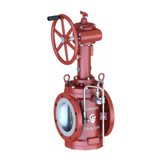
- Page 1 E N G I N E E R E D & P R O C E S S V A L V E S Installation, Operation and Maintenance Manual GENERAL VALVE ® ® Twin Seal ™ ™ Double Block and Bleed Plug Valve GENERAL VALVE ®...
- Page 2 E N G I N E E R E D & P R O C E S S V A L V E S Installation, Operation and Maintenance Manual 07/2011 / IOM-GEN-TWIN-03...
-
Page 3: Table Of Contents
E N G I N E E R E D & P R O C E S S V A L V E S TABLE OF CONTENTS GENERAL VALVE TWIN SEAL ® ™ Installation..................... 4 Operation...................... 5 Series 400, 800 & 900 Integral Bushing/Retained Ring Gland ............ -
Page 4: Installation
E N G I N E E R E D & P R O C E S S V A L V E S INSTALLATION Orientation Flange Fasteners Twin Seal valves may be installed in any position. Certain Twin Seal flange holes are drilled and tapped, when there is no possibility of fitting a hexagonal nut behind the Flow Direction flange. -
Page 5: Operation
E N G I N E E R E D & P R O C E S S V A L V E S Pressure Test Twin Seal valves can be hydrostatically pressure-tested after installation, to full API 6D limits per Table 3 below. Table 3 Valve figure No. -
Page 6: Integral Bushing/Retained Ring Gland
E N G I N E E R E D & P R O C E S S V A L V E S INTEGRAL BUSHING/RETAINING RING GLAND Typical Arrangement of: 2” C811 2” C821 3” CA811 3” CA821 The smallest of the Twin Seal valves do not require discrete bushings due to minimal hydro seating forces within the valve. -
Page 7: Bushings/One Gland
E N G I N E E R E D & P R O C E S S V A L V E S BUSHINGS/ONE GLAND Typical Arrangement of: 2” C841 6” C911 12” C811 2” C851 6” C921 12” C821 2”... -
Page 8: Bearings/Duel Retention
E N G I N E E R E D & P R O C E S S V A L V E S BEARINGS/DUAL RETENTION Typical Arrangement of: 12” C941 14” C841 16” C921 18” CA821 18” C911 20” CA821 CA841 20”... -
Page 9: Bearings/Internally & Externally Retained
E N G I N E E R E D & P R O C E S S V A L V E S BEARINGS/INTERNALLY & EXTERNALLY RETAINED Typical Arrangement of 10” CB841 10” C941 12” CB841 16” CA841 16” C941 20”... -
Page 10: Series 8800
E N G I N E E R E D & P R O C E S S V A L V E S GENERAL VALVE Twin Seal SERIES 8800 ® ™ 6 GLAND 77 LOCATING PIN 62B BACKUP RING 2 BONNET 62A O-RING 49 GASKET... -
Page 11: Model 375H
E N G I N E E R E D & P R O C E S S V A L V E S GENERAL VALVE Twin Seal MODEL 375H ® ™ Exploded View OPERATOR DISASSEMBLY Item 375 H Description Req’d Unscrew (17) and remove indicator flag (5). -
Page 12: Operators
E N G I N E E R E D & P R O C E S S V A L V E S GENERAL VALVE Twin Seal MODEL 500H & 625H ® ™ Exploded View Item 500 H 625 H Item 500 H 625 H... - Page 13 E N G I N E E R E D & P R O C E S S V A L V E S Cross Section 625 H is Used on Models: 500 H is Used on Models: 2” C851 2”...
-
Page 14: Model 376G & 501G
E N G I N E E R E D & P R O C E S S V A L V E S GENERAL VALVE Twin Seal Model 376G & 510G ® ™ Exploded View Cross Section 49-648-020 PLASTIC SHIM Section A-A 32 UPPER... - Page 15 E N G I N E E R E D & P R O C E S S V A L V E S GENERAL VALVE Twin Seal Model 376G & 510G ® ™ OPERATOR DISASSEMBLY Remove the indicator pin (34) and pull the indicator stem (8) up through the gear housing (2). Remove the stop screw (35) and dowel pin (33).
- Page 16 E N G I N E E R E D & P R O C E S S V A L V E S OPERATOR ASSEMBLY Install O-Ring (21) in the stem bushing (14) in the operator housing (1). Place bearing (23) in the top of the operator housing (1). Apply a liberal coating of grease to all surfaces of the operator stem (3) and the upper stem (4).
-
Page 17: Model 625G, 751G & 755G
E N G I N E E R E D & P R O C E S S V A L V E S GENERAL VALVE Twin Seal Model 625G, 751G & 755G ® ™ Cross Section Exploded View 26, 28 15, 42 40, 30 625G is Used on Models:... - Page 18 E N G I N E E R E D & P R O C E S S V A L V E S GENERAL VALVE Twin Seal Model 625G, 751G, & 755G ® ™ OPERATOR DISASSEMBLY Unscrew (39) and remove indicator flag (11). Remove stem protector (24).
- Page 19 E N G I N E E R E D & P R O C E S S V A L V E S OPERATOR ASSEMBLY Place one of the two bearings (27) on upper stem (4). NOTE: This bearing is assembled such that the wide surface of the inner race seats on the upper stem shoulder.
-
Page 20: Model 1261G & 1261-7G
E N G I N E E R E D & P R O C E S S V A L V E S GENERAL VALVE Twin Seal Model 1261G 1261-7G ® ™ Exploded View Cross Section 43 NOT 1261G is Used on Models: SHOWN 12”... - Page 21 E N G I N E E R E D & P R O C E S S V A L V E S GENERAL VALVE Twin Seal Model 1261G & 1261-7G ® ™ OPERATOR DISASSEMBLY Unbolt and remove the gear housing (2). Unscrew (37) and remove indicator flag (9).
- Page 22 E N G I N E E R E D & P R O C E S S V A L V E S GENERAL VALVE Twin Seal Model 1261G & 1261-7G ® ™ OPERATOR ASSEMBLY Install the two bearings (26) at top of upper stem (3). NOTE: These are radial thrust bearings and must be installed such that the widest surfaces of the inner raceways are back to back.
-
Page 23: Model 1276G
E N G I N E E R E D & P R O C E S S V A L V E S GENERAL VALVE Twin Seal Model 1276G ® ™ Exploded View Cross Section 49-649-20 7 29 30 SHIM (NOT SHOWN) 1276G is Used on Models:... - Page 24 E N G I N E E R E D & P R O C E S S V A L V E S GENERAL VALVE Twin Seal Model 1276G ® ™ OPERATOR DISASSEMBLY Item 1276G Part Description Req’d Turn handwheel counter clockwise to full open position. 27-541 Indicator Shaft Remove set screw (39) and indicator flag (11).
- Page 25 E N G I N E E R E D & P R O C E S S V A L V E S GENERAL VALVE Twin Seal Model 1276G ® ™ OPERATOR ASSEMBLY Install the two bearings (28) at the top end of the upper stem (5). NOTE: These are radial thrust bearings and must be installed such that the widest surfaces of the inner race ways are back to back.
-
Page 26: Model 1500G
E N G I N E E R E D & P R O C E S S V A L V E S GENERAL VALVE Twin Seal Model 1500G ® ™ Cross Section Exploded View 11, 39 39, 40 **SHIELDS (NOT SHOWN) 25-93-424... - Page 27 E N G I N E E R E D & P R O C E S S V A L V E S GENERAL VALVE Twin Seal Model 1500G ® ™ OPERATOR DISASSEMBLY Turn worm shaft counter-clockwise to full open position. Remove set screw (39) and indicator flag (11) Remove the stem protector (24).
- Page 28 E N G I N E E R E D & P R O C E S S V A L V E S GENERAL VALVE Twin Seal Model 1500G ® ™ OPERATOR ASSEMBLY Install the two bearings (28) and bearing retainer at the top end of the upper stem (5). NOTE: These are radial thrust bearings and must be installed such that the widest surfaces of the inner raceways are back to back.
-
Page 29: The Dtr System Explained
E N G I N E E R E D & P R O C E S S V A L V E S UNDERSTANDING THE DIFFERENTIAL THERMAL RELIEF BLEED SYSTEM SCOPE This specification addresses the proper functioning, trouble shooting, and repair of the GENERAL VALVE TWIN SEAL differential (pressure) thermal relief (DTR) bleed system. - Page 30 E N G I N E E R E D & P R O C E S S V A L V E S WHY IT IS ESPECIALLY IMPORTANT ON MOTOR OPERATED VALVES Electrically powered actuators or motor operators are UNSEATING CONTINUES configured normally to bypass or ignore the opening torque limiter as the valve just begins unseating.
-
Page 31: Operation & Maintenance
Cameron’s Valves & Measurement group provide only new corrected by one of the following: factory replacement parts which are supplied through the local Cameron Sales Office, details of which can be found Operate valve through open-close cycle while fluid at www.c-a-m.com. - Page 32 E N G I N E E R E D & P R O C E S S V A L V E S TRADEMARK INFORMATION GENERAL VALVE is a registered trademark which is owned by Cameron. ® This document contains references to registered trademarks or product designations, which are not owned by Cameron. Trademark Owner Form-a-Gasket Permatex...
- Page 33 E N G I N E E R E D & P R O C E S S V A L V E S Installation, Operation and Maintenance Manual 07/2011 / IOM-GEN-TWIN-03...
- Page 34 E N G I N E E R E D & P R O C E S S V A L V E S VALVES & MEASUREMENT 3250 Briarpark Drive, Suite 300 Houston, TX 77042 USA Toll 800 323 9160 For the most current contact and location information go to: www.c-a-m.com Installation, Operation and Maintenance Manual 07/2011 / IOM-GEN-TWIN-03...
Need help?
Do you have a question about the GENERAL VALVE Twin Seal 400 Series and is the answer not in the manual?
Questions and answers