Table of Contents
Advertisement
Quick Links
Advertisement
Chapters
Table of Contents

Related Manuals for Meva MevaLite


Summary of Contents for Meva MevaLite
- Page 1 MevaLite Technical Instruction Manual June 2022...
- Page 2 MevaLite panels are available in 4 different heights (9’, 6', 4’, and 3’) and in 5 different widths (3’, 2’, 1’-6”, 1’-0”, and 6”). In addition, 2’-6" wide multi-purpose panels are available in each height. These panels have multi-adjustment profiles for placing ties or column clamps and are ideal for forming 90°...
-
Page 3: Table Of Contents
Æ This manual contains information and instructions on how to use The MevaLite Panel ................4 MEVA equipment in a safe and efficient manner. All construction Multi-Purpose Panels ................5 personnel involved with the use of this equipment (“User”) must be The alkus Sheet..................6 familiar with the contents of this manual. -
Page 4: The Mevalite Panel
Wall formwork MevaLite The MevaLite Panel Fig. 4.1 MevaLite panel Fig. 4.2 The aluminum frames are manufactured of closed profiles which are welded in mitered joints. These profiles are provided with a groove and an integrated protection for the Fig. 4.2 forming face. -
Page 5: Multi-Purpose Panels
Wall formwork MevaLite Multi-purpose Panels The multi-purpose panels are ideal for forming 90° corners, columns, pilasters, bridge abutments and Holes with threaded nuts in frame at connections to existing walls. multi-adjustment profile elevation The panels are provided with multi- adjustment profiles where column clamps or ties are mounted. -
Page 6: The Alkus Sheet
Wall formwork MevaLite The alkus Sheet The poly-propylene and aluminum composite forming face has all the positive properties of plywood plus important advantages: longer Frame profile + plywood face Frame profile + alkus sheet life span, greater load-bearing capacity, better nail-holding ability, fewer and easier repairs, 100 % recyclability. -
Page 7: Panel Connection
Wall formwork MevaLite Panel Connection The panels are connected quickly and efficiently with the EA-assembly lock regardless of their orientation (Fig. 7.1, 7.2). The lock can be attached on the frame at any position, and its 5-point contact not only draws the panels together but aligns them as well. -
Page 8: Tie Systems
Wall formwork MevaLite Tie Systems 5/8" (15mm) Taper Tie 5/8" (15mm) Taper Tie Description Ref.-No. SWL = 18.75 KIPS Factor of Safety = 2:1 Articuated flange nut 15/120 ........29-900-10 5/8" (15mm) Taper Tie Stock Sizes 16/41 - 16" Taper length, 41" Overall ..2-500-2990131 24/49 - 24"... -
Page 9: System Panel Sizes
Wall formwork MevaLite System Panel Sizes High degree of flexibility Panel height: 9’ The formwork is extended in 6" 1'-6" height using panels assembled vertically or horizontally on top of the lower panels. The wide range of panel heights and widths ensures: Æ... - Page 10 Wall formwork MevaLite System Panel Sizes High degree of flexibility The formwork is extended in height using panels assembled vertically or horizontally on top of the lower panels. The wide Panel height: 4’ range of panel heights and widths 1'-6"...
- Page 11 Wall formwork MevaLite System Panel Sizes Multi-purpose panels The multi-purpose panels are ideal for forming 90° corners, columns, pilasters, bridge abutments and connections to existing walls. The panels are provided with multi-adjustment profiles where column clamps or ties are mounted.
-
Page 12: Tie Placement
Fig. 12.1 Fig. 12.2 (Fig. 12.5), unless otherwise indicated on MEVA layout drawings. When using tie claws, the ties can be placed at the outside edge of Maximum Incline the panels. For example; when Tie System Angle [α]... -
Page 13: Stacking Panels
Wall formwork MevaLite Stacking Panels For stacked panel conditions Top of concrete where the top of concrete is ≤ 1' above the panel below it is not necessary to install ties in the top panel (Fig. 13.1), unless a walkway bracket is attached or the panel below is 3' high. -
Page 14: 90°Corners
Wall formwork MevaLite 90° Corners The MevaLite inside corner rigid is provided with tie holes, and consists of a aluminum frame with a replaceable alkus face (Fig. 14.1). The length of each side is 1' (Fig. 14.2). The MevaLite inside corner elastic is designed to flex to allow for easier stripping, and the alkus face is replaceable (Fig. 14.3). - Page 15 Wall formwork MevaLite 90° Corners Standard Panels and Outside ≤ 12" Corners The connection and rail support requirements for outside corner assemblies depend on the wall thickness. Locks required at For wall thicknesses ≤ 12", outside corner joints: additional locks are only required...
- Page 16 Wall formwork MevaLite 90° Corners > 18"≤ 24" For wall thicknesses > 18" but ≤ 24", in addition to extra locks Locks required at all steel rails must also be mounted panel joints within 9' at all tie elevations except the of outside corner:...
- Page 17 Wall formwork MevaLite 90° Corners Multi-Purpose Panels ≤ 9" ≤ 13" A multi-purpose panel (MPP) can be used to form 90° outside corners by connecting a standard panel with column clamps. The column clamp is secured with a Column flange nut 100 or an articulated clamp flange nut 15/120.
-
Page 18: Articulated Corners
Wall formwork MevaLite Articulated Corners Acute and obtuse angled corners are formed using MevaLite articulated inside and outside corners. Steel rails are attached to the multi-function profile with flange screws at each tie hole elevation (Fig. 18.1 & 18.2). The rails at the outside corner must... - Page 19 Form the fill distance with the widest MevaLite panel possible and a wood filler ≤ 6" wide (if Wood blocking needed). Always locate wood fillers next to a tied MevaLite panel. α > 100° Fig. 19.1 Note: See the "90° Corners"...
- Page 20 Form the fill distance with the widest MevaLite panel possible and a wood filler ≤ 6" wide (if needed). Always locate wood fillers next to a tied MevaLite panel. α ≤ 100° Fig. 20.1 Fill Distance, y (inches) for 16" - 24" Wall Thicknesses Angle, α...
-
Page 21: Stripping Corners
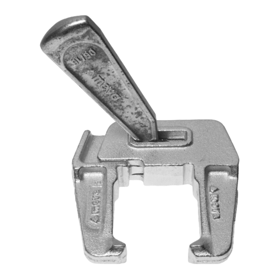
Wall formwork MevaLite Stripping Corners Stripping corners are designed specifically for use when forming shafts (Fig. 21.1 - 21.3), stairwell cores and in confined working conditions. The corner is designed to allow the corner to retract inward for stripping, while still keeping the... - Page 22 Wall formwork MevaLite Stripping Corners - Lever Tool Zeichnung Nr. 100501_0127 _öffnen_Schritt_1-A Zeichnung Nr. 100501_0127 _öffnen_Schritt_1-B Stripping the corner: To strip the corners, remove the wedge from the top corner (Fig. 22.1 and 22.2). Apply the lever tool to the top of the corner and place the pin of the tool into the corner plate.
- Page 23 Wall formwork MevaLite Stripping Corners - Lever Tool Resetting the corner: Remove the pin to the connecting plate that is at the bottom of the corner. Place the pin to the lever tool in the plate of the corner (Fig. 23.1).
- Page 24 Wall formwork MevaLite Stripping Corners - Retract and Reset Tool Stripping Corner - Retract and Reset Tool The retract and reset tool (Fig. 24.1) is used to easily activate the stripping corner from above with an impact wrench, a ratchet or a wrench.
- Page 25 Wall formwork MevaLite Stripping Corners - Retract and Reset Tool Stripping: Turning the hexagonal nut with an impact wrench (Fig. 25.1), a ratchet (Fig. 25.2) or a wrench moves the stripping mechanism upwards. This activates the stripping corner and separates the shaft formwork from the concrete walls (Fig. 25.3...
- Page 26 Wall formwork MevaLite Stripping Corners - Retract and Reset Tool Re-setting: To reset the corner again, just push the stripping mechanism downwards by using the same tools (Fig. 26.1 - Fig. 26.4). Once the inner channel is pushed all the way down, the corner is reset into place.
- Page 27 Wall formwork MevaLite Stripping Corners Stacking/Connecting stripping corners: To stack corners, make sure that you have a level surface and both corners are in the expanded (ready to pour) position. Slide the top of one corner under the mechanism of the other corner.
-
Page 28: Columns
Wall formwork MevaLite Columns Columns with Multi-Purpose- 1” - 23” 2” - 24” Tensioning screw Panels: at each tie hole elevation, typ. Multi-purpose panels can be used to form columns of varying sizes up to 24” in 1” increments. The... - Page 29 = corners. To form columns with 9' panel - 7 locks 1350 psf. sizes in between the MevaLite 6' panel - 5 locks panel widths, the next largest 4' panel - 4 locks panel size is used and the forms 3' panel - 3 locks are furred out on the inside.
-
Page 30: Fillers
(Fig. 30.2), or cantilevered over one tie to RAIL 6' support the filler and adjacent MevaLite panel (Fig. 30.3). The rail supported panel next to the filler Flange screw 18 can be up to 3' wide. Fig. 30.2 Fillers up to 6.5" wide, rails between two ties 1"... - Page 31 Wall formwork MevaLite Fillers Fillers over 6.5" wide Job-built fillers over 6.5" wide require steel rails at each tie hole elevation to support the Filler width filler. The maximum filler width is determined using the table in Fig. 31.1. The job-built filler must be...
-
Page 32: Intersections
Wall formwork MevaLite Intersections Intersecting walls are formed using inside corners and standard panels (Fig. 32.1 - Fig. 32.4). Fillers are R 3' used to make adjustments for different wall thicknesses. Steel rails may be required depending on the filler configuration (see the "Fillers"... -
Page 33: Bulkheads
30" thick. The 4 1/4" min. bulkhead bracket safe working load limits are as follows: Shear/End Reaction = 2666 lb. MevaLite panel, typ. Tension = 2666 lb. End panel width Bending Moment = 5091 ft-lb. Fig. 33.1 Brackets may not be spaced closer together than the panel cross members. - Page 34 The column clamp's safe working plywood bulkhead Articulated flange load in tension is 4750 lb on nut 15/120 MevaLite panels. Column clamps must be installed so that they straddle the panel cross members. The ends of the vertical bulkhead panels are tied by installing taper...
-
Page 35: Adjoining Walls
Wall formwork MevaLite Adjoining Walls These figures show example formwork details at adjoining walls. Details for lap conditions at a previous pour are shown in Figures 35.1 and 35.2. The detail for formwork perpendicular to an existing wall is shown in Fig. 35.3. Three foot rails are used so that both tubes of the rail section support the filler. -
Page 36: Pilasters
Wall formwork MevaLite Pilasters Pilasters are easily formed using Bulkhead bracket Hardwood blocking panels and inside corners. The pilaster face panel can be supported with either bulkhead brackets (Fig. 36.1 and 36.2) or steel rails (Fig. 36.3). In both Note: cases hardwood blocking must be See the "Bulkheads"... -
Page 37: Pilasters At Corners
Wall formwork MevaLite Pilasters at Corners Example formwork solutions for wall corners with pilasters are Add sill below shown in Fig. 37.1 - Fig. 37.3. panels to avoid tie Different pilaster sizes and wall interference thicknesses can be accomodated by using combinations of fillers and boxouts. -
Page 38: Wall Offsets
Wall formwork MevaLite Wall Offsets Wall offsets up to 2" can be formed by offsetting the Fig. 38.4 corresponding panels, and adding rails and wood blocking (Fig. 38.1). R 3' Offsets between 2" and 7 3/4" can be formed using inside corners Hardwood blocking (Fig. 38.2). -
Page 39: Vertical Offsets
Wall formwork MevaLite Vertical Offsets The assembly lock can be attached at any position on the frame profile, so all panels can be safely connected even when offset from each other vertically (Fig. 39.1). Job built fillers are used to transition between vertical and inclined panels (see the "Fillers"... -
Page 40: Horizontal Panels
(Fig. 40.5 - 40.8). For pour heights up to 4', the maximum spacing MevaLite panel of the foundation spanners is Drive nut 60 2'-3". For pour heights up to 3', the maximum spacing of the Fig. -
Page 41: Wall Braces
Wall formwork MevaLite Wall Braces Wall braces and accessories are Fig. 41.2 available for plumbing and aligning the formwork (Fig. 41.1). If braces are used to resist wind or other loads, the bracing system and anchorages must be designed by a competent person in accordance with all applicable governmental regulations, codes, and ordinances. - Page 42 24'-11" 1819 [2473] Primary value listed is based on application as brace installed at 60° to horizontal and accounts for MevaLite panel connection with multi-function profile transverse working load limit of 1576 lb. Value in [brackets] is safe working load of brace alone.
- Page 43 7'-3" 1819 [4496] Primary value listed is based on application as brace installed at 60° to horizontal and accounts for MevaLite panel connection with multi-function profile transverse working load limit of 1576 lb. Value in [brackets] is safe working load of brace alone.
-
Page 44: Form Walkways
Wall formwork MevaLite Form Walkways Walkway Bracket The walkway bracket contains an integral self-locking pin, and is mounted to a multi-function profile (Fig. 44.1). Planking, toprail, midrail and toeboard To mount the bracket: components must comply with federal, Rotate it 45°, insert the pin into... -
Page 45: Crane Hook
Wall formwork MevaLite Crane Hook The safe working load of a crane hook (Fig. 45.1) is 1,300 lbs (Safety factor: 5:1 against failure) The handling is very simple: Open the safety lever as far as possible (Fig. 45.2), then move the crane hook onto the panel profile until the claw engages completely in the groove. -
Page 46: Gang Forming
Wall formwork MevaLite Gang Forming Each crane hook must be attached at a panel joint (Fig. 46.1) or above Rigging (by others), typ. a stiffener or panel joint when the top panels are horizontal. The number and location of crane Crane-hook, typ. - Page 47 Wall formwork MevaLite Gang Forming If rails required for lifting interfere with those needed for concrete placement, reconfigure/remove lifting rails after setting gangs, then reset to lifting configuration prior to stripping. 60° min. Rails must extend to next cross member...
-
Page 48: Adjustable Shearwall Bracket
Imperial profiles welded to the top so that assembly locks can be used to connect the formwork Uni-assembly lock to the brackets. With MevaLite panels wood blocking is required to make the connection between the different profiles (Fig. 48.1 2" lumber cut to 4 1/4" wide and 48.2). -
Page 49: Assembly, Erection And Stripping
Wall formwork MevaLite Assembly, Erection and Stripping Planning Stage Planning and preparation are the keys to a successful application of any formwork system. To determine the amount of formwork material that will be needed, a number of influencing factors should be taken into account such as: Æ... - Page 50 Wall formwork MevaLite Assembly, Erection and Stripping General The following assembly, erection, and stripping information is provided as a guide, and is not intended to be all-inclusive. The contractor is responsible for the safe usage of the formwork equipment in accordance with all applicable government regulations, codes, and ordinances.
- Page 51 Wall formwork MevaLite Assembly, Erection and Stripping Erecting the First Side 4. Remove the crane hooks. For handset erection: 5. Proceed with setting the other gangs along the first side. 1. Erect the first panel and immediately attach a brace, anchor 6.
- Page 52 Wall formwork MevaLite Assembly, Erection and Stripping Erecting the Second Side 3. Continue erecting the second (Closing) side panels in the same manner, connecting them with assembly For handset erection: locks (Fig. 52.2). 1. Depending on the tie system, 4. Install the walkway brackets if some tie components may need to used on second side.
- Page 53 The maximum lateral concrete pressure shall be as indicated in this manual (or on MEVA formwork drawings if provided), taking into account all limiting factors and details of the formwork layout. Job...
- Page 54 Wall formwork MevaLite Assembly, Erection and Stripping For gang forming: Formwork shall not be stripped until the requirements of the project specifications have been met. If braces were installed on the first side only, strip the second side formwork first.
-
Page 55: Transport
Fig. 55.5 Accessories such as assembly locks, flange screws, articulated flange Fig. 55.1 Fig. 55.2 nuts, ties, crane hooks, etc. can be stored in the MEVA storage boxes. Fig. 55.3 Fig. 55.4 Description Ref.-No. Fig. 55.5 Storage box .......27-000-10 Stacking rack ......27-000-20... -
Page 56: Service
We offer our customers the option of renting supplementary material during peak times. We also give prospective customers the chance to test MEVA formwork so they can see its benefits for themselves in actual use. RentalPlus Since MEVA started the flat... -
Page 57: Notes
Notes ........ - Page 58 Notes ........
-
Page 59: Product List
Please note: This product list includes all parts necessary for most applications, along with the corresponding dimensions. For parts required for a special application of MevaLite, please refer to our MEVA pricelist. Content Alignment rails ..................74 ML-panels ..................60 - 66 Articulated flange nut 15/120 ..............75... -
Page 60: Ml-Panels
Wall formwork MevaLite ML-panels Ref.-No. Description / Application sq. ft. All panels available are listed on the right. 22-500-20 ....ML-panel ......9‘ x 3‘ ...... 27.0 ..136.2 For description and dimensions refer to the 22-500-30 ....ML-panel ......9‘ x 2’ ...... 18.0 ....96.6 following pages. - Page 61 Wall formwork MevaLite ML-panels Ref.-No. Description / Application sq. ft. Panel height 9’ 22-500-20 ....ML-panel ......9‘ x 3‘ ...... 27.0 ..136.2 For panel height 9’: 7 cross stiffeners, of 22-500-30 ....ML-panel ......9‘ x 2’ ...... 18.0 ....96.6 which 7 are multi- function profiles with welded DW-threaded nuts.
- Page 62 Wall formwork MevaLite ML-panels Ref.-No. Description / Application sq. ft. Panel height 9’ 22-500-40 ....ML-panel ......9’ x 1’-6” ....13.5 ....79.6 For panel height 9’: 7 cross stiffeners, of 22-500-50 ....ML-panel ......9’ x 1’ ......9.0 ....57.5 which 7 are multi- function profiles with 22-500-60 ....ML-panel ......9’...
- Page 63 Wall formwork MevaLite ML-panels Ref.-No. Description / Application sq. ft. Panel height 6’ 22-501-20 ....ML-panel ......6’ x 3’ ...... 18.0 ....85.8 For panel height 6’: 5 cross stiffeners, of 22-501-30 ....ML-panel ......6’ x 2’ ...... 12.0 ....67.7 which 5 are multi- function profiles with 22-501-40 ....ML-panel ......6’...
- Page 64 Wall formwork MevaLite ML-panels Ref.-No. Description / Application sq. ft. Panel height 6’ 22-501-20 ....ML-panel ......6’ x 3’ ...... 18.0 ....85.8 For panel height 6’: 5 cross stiffeners, of 22-501-30 ....ML-panel ......6’ x 2’ ...... 12.0 ....67.7 which 5 are multi- function profiles with 22-501-40 ....ML-panel ......6’...
- Page 65 Wall formwork MevaLite ML-panels Ref.-No. Description / Application sq. ft. Panel height 4’ 22-502-20 ....ML-panel ......4’ x 3’ ...... 12.0 ....62.5 For panel height 4’: 3 cross stiffeners, of which 22-502-30 ....ML-panel ......4’ x 2’ ......8.0 ....46.5 3 are multi- function profiles with welded 22-502-40 ....ML-panel ......4’...
- Page 66 Wall formwork MevaLite ML-panels Ref.-No. Description / Application sq. ft. Panel height 3’ 22-503-20 ....ML-panel ......3’ x 3’ ......9.0 ....47.6 For panel height 3’: 1 cross stiffener, of which 22-503-30 ....ML-panel ......3’ x 2’ ......6.0 ....34.2 1 is a multi- function profile with welded 22-503-40 ....ML-panel ......3’...
-
Page 67: Ml-Multi-Purpose Panels
Wall formwork MevaLite ML-multi-purpose panels Ref.-No. Description / Application sq. ft. The multi-purpose panel can be used to form pilasters, 22-500-25 ....ML-multi-purpose panel ..9’ x 2’-6“ ....22.5 ..128.3 corners, columns, bridge abutments and connections 22-501-25 ....ML-multi-purpose panel ..6’ x 2’-6“ ....15.0 ....90.4 to existing walls. -
Page 68: Ml-Inside Corner Elastic
Wall formwork MevaLite ML-inside corner elastic Ref.-No. Description / Application sq. ft. consists of an aluminum frame and a 22-505-60 ....ML-inside corner elastic .. 9’ x 1’ ......18 ...91.5 replaceable alkus-sheet; for 90°angles. 22-505-70 ....ML-inside corner elastic .. 6’ x 1’ ......12 ...64.2 22-505-80 ....ML-inside corner elastic .. -
Page 69: Ml-Stripping Corner
Wall formwork MevaLite ML-stripping corner Ref.-No. Description / Application sq. ft. steel; side length = 1‘, designed with 3 pieces to 22-508-00 ....ML-stripping corner 9’ ........18 ..364.3 permit inward movement to facilitate stripping and 22-508-10 ....ML-stripping corner 6’ ........12 ..269.5 resetting of formwork e.g. -
Page 70: Ml-Outside Corner
Wall formwork MevaLite ML-outside corner Ref.-No. Description / Application aluminum, together with MevaLite-panels and 22-505-10 ....ML-outside corner 9’ ............20.5 EA-assembly locks it provides a solid outside 23-505-20 ....ML-outside corner 6’ ............13.7 corner assembly for 90° angles with high 23-505-30 ....ML-outside corner 4’ .............9.5 resistance to tensile force. -
Page 71: Ml-Articulated Inside Corner
Wall formwork MevaLite ML-articulated inside corner Ref.-No. Description / Application sq. ft. steel; side length = 1‘; adjustable from 70° to 22-506-10 ....ML-articulated inside corner 9’ ......18 ..192.5 275°; stop points at 70°, 90° and 135°; plugs 22-506-20 ....ML-articulated inside corner 6’ ......12 ..132.7 D 27/30 (Ref.-No. -
Page 72: Ml-Filler
Wall formwork MevaLite ML-filler Ref.-No. Description / Application sq. ft. for length adjustments of 1“ to 3“. 22-507-10 ....ML-filler ......9’ x 3” ...... 2.30 ..22.7 22-507-15 ....ML-filler ......9’ x 2” ...... 1.50 ..16.5 22-507-20 ....ML-filler ......9’ x 1” ...... 0.75 ..13.0 22-507-30 ....ML-filler ......6’... -
Page 73: Double Wedge Lock
Ref.-No. Description / Application galvanized; for connecting panels with fillers; 29-400-85 ....Uni-assembly lock 22 .............7.9 clamping length = 8 21/32“, spans fillers up to 6 1/2“ (when using MevaLite panels). from 0” to 8 21/32” 13 1/2” Double wedge lock Ref.-No. -
Page 74: Alignment Rails
Wall formwork MevaLite Alignment rails Ref.-No. Description / Application galvanized; to brace panel joints for gang 2-500-2331040 ....Steel rail 12' ............155.0 forming, to support fillers and to build 2-500-2331035 ....Steel rail 8' .............80.0 bulkheads. Is attached to formwork with flange 2-500-2331030 .... -
Page 75: Articulated Flange Nut 15/120
Wall formwork MevaLite ML-column clamp Ref.-No. Description / Application galvanized, permits connection of panels 29-210-70 ....ML-column clamp ..............5.4 at an angle of 90°. To form columns with 10 1/2” 7/8” 2 1/4” 5/16” 5/16” ML-multi-purpose panels; needs one flange 4”... -
Page 76: Drive Nut 60
Wall formwork MevaLite ML-tensioning screw Ref.-No. Description / Application to connect two ML-multi-purpose panels at an 29-210-80 ....ML-tensioning screw .............2.6 angle of 90° with each other 1 7/8” 3” 1 1/8” 3 5/16” 7 1/2” 4” 9 3/8” Flange screw 18/28 Ref.-No. -
Page 77: Taper Tie
2-500-2990135 ....32“ ........57” ........7.7 DW 5/8” Tie claw 23 Ref.-No. Description / Application galvanized; permits tieing directly above or 29-901-44 ....Tie claw 23 ................0.4 beside MevaLite panels. 1 1/16” 25/32” 2” 45/64” Technical Instruction Manual - Product list / June 2022 ML-77... -
Page 78: Ml-Crane Hook
Wall formwork MevaLite ML-crane hook Ref.-No. Description / Application to move panels and lift gangs; self-locking 29-103-10....ML-crane hook ..............12.6 mechanism; admissible load-bearing capacity: 1,300 lbs; for application and safety test – see „Crane Hook“ section. 3” 2” 4 1/2” 5/16”... -
Page 79: Guard-Railing Post
Wall formwork MevaLite Walkway bracket 90 Ref.-No. Description / Application galvanized; is attached to the multi-function 29-106-00 ....Walkway bracket 90 (3') ............22.0 profile and secured to the multi-function profile below by means of a flange screw 18. The planking has to be bolted to the brackets. -
Page 80: Side Railing
Ref.-No. Description / Application railing post 29-108-50 ....Support 800 for guard-railing post ........22.5 galvanized; allows plugging in of all MEVA guard-railing posts. The support 800 is mounted to MEVA wall-formwork panels by using a flange screw 18. The angle between wall formwork and guard- railling post is about 15°. -
Page 81: Bulkhead Bracket 60/23
29-105-60 ....Bulkhead bracket 60/23 ............44.1 Bulkhead bracket 60/23: suited for modular panels with a profile width of 7/8“ (MevaLite) and 2 3/8” (Imperial). For wall thicknesses up to 30” Technical Instruction Manual - Product list / June 2022... -
Page 82: Articulated Foot Plate
Wall formwork MevaLite Articulated foot plate Ref.-No. Description / Application galvanized; to anchor braces with up to 2 1/4“ 29-802-48 ....Articulated foot plate ............5.1 (58 mm) outside diameter, includes M16x90 bolt and cotter pin. 2” 6 7/8” Ø 3/4” Ø 7/8”... -
Page 83: Push-Pull Prop R 160
Wall formwork MevaLite Push-pull prop R 160 Ref.-No. Description / Application galvanized; high tensile and compression 29-109-40 ....Push-pull prop R 160 ............24.3 strength, for aligning formwork. Articulated foot plate and formwork-prop connector must be ordered separately. Adjustment range: 4’-6” to 6’-6”. -
Page 84: Push-Pull Prop R 460
Wall formwork MevaLite Push-pull prop R 460 Ref.-No. Description / Application galvanized; high tensile and compression 29-109-80 ....Push-pull prop R 460 ............78.9 strength, for aligning formwork. Articulated foot plate and formwork-prop connector must be ordered separately. Adjustment range: 11’-2” to 17’-0”. -
Page 85: Shoe Plate 23
Ref.-No. Description / Application galvanized; to connect the foundation tape to 29-307-85 ....Foundation spanner ML ............3.7 MevaLite panels; it serves as bottom tie when panels are assembled in horizontal position. Two (2) foundation spanners are required per tieing position. Technical Instruction Manual - Product list / June 2022... -
Page 86: Foundation Tape
Wall formwork MevaLite Foundation tape Ref.-No. Description / Application galvanized; hole spacing 2” (50 mm); 29-307-50 ....Foundation tape ..............44.1 hole diameter 5/8” (16 mm); length 164’ (50 m); adm. tension force 2.2 kips (10.0 KN); to be cut at hole center. Together with... - Page 87 Notes ........
- Page 88 International Sales & Service USA / Canada Headquarters (Germany) MEVA Formwork Systems, Inc. MEVA Schalungs-Systeme GmbH A-Pfaffstätten, Tel. +43 2252 20900-0 Industriestrasse 5 AUS-Adelaide, Tel. +61 8 82634377 2000 Airpark Dr. D-72221 Haiterbach Benelux, Gouda, Tel +31 182 570770 Springfield, OH 45502 Tel.
Need help?
Do you have a question about the MevaLite and is the answer not in the manual?
Questions and answers