Table of Contents
Advertisement
Quick Links
Advertisement
Table of Contents

Summary of Contents for KERN DHS
- Page 1 System Manual...
- Page 3 Kern Electronics & Lasers, Inc. d.b.a. Kern Laser Systems Wadena, Minnesota 56482 KCAM© is a copyright protected software. Manual Rev 2.11.2015 Kern Electronics & Lasers, Inc., All Rights Reserve...
- Page 4 All information in this document is subject to change without notice. Kern Electronics & Lasers, Inc. makes no warranty as to the usefulness of its products for any particular application. It is the Buyer’s responsibility to develop processes within the operating envelope of Kern products.
- Page 5 Contact Information Kern Laser Systems 1501 Industrial Drive Wadena, MN 56482 U.S.A. Phone: 218-631-2755 Fax: 218-631-3476 Email: info@kernlasers.com Website: www.kernlasers.com Office Hours Monday – Friday: 8AM – 4:30PM Central Time Customer Service Toll Free: 888-660-2755 (US and Canada) Phone: 218-631-2755 Email: help@kernlasers.com...
-
Page 6: Table Of Contents
Table of Contents Getting Started Safety ..........................1 Sealed Beam Path ......................2 Laser Processed Materials and Applicable Standards ............. 2 CDRH Standards ......................2 Material Capability and Fume Extraction ................3 Mandated Safety Labels ....................4 CDRH Procedures for Compliance ..................6 System Requirements ...................... - Page 7 CorelDRAW Setup ......................50 KCAM Setup ........................50 CorelDRAW Initial Setup ........................51 Kern EMF Printer Driver ....................51 Creating a .PLT Cutting File ....................52 Creating a .TIF Engraving File ..................52 Setting the Cut Order ...................... 53 10 AutoCAD Printing to KCAM......................
- Page 8 A Message from the President Thank you for choosing a Kern Laser Cutting and Engraving System. All of our systems are designed, built, tested, and delivered with quality, productivity and customer satisfaction in mind. With proper care and minimal maintenance of your system, you should receive years of productivity from your laser system.
-
Page 9: Safety
Everyone at Kern takes great pride in manufacturing a quality laser system and providing the best technical support for years after the sale. Feel free to give us a call when in need of assistance with your Kern Laser System. -
Page 10: Sealed Beam Path
Operating Modes Kern’s DHS model is normally operated in Automatic mode. In Manual mode it is possible to fire the laser source, operate X and Y motion systems and check air pressure. Manual mode can only be used if all safety interlocks are in operation. -
Page 11: Material Capability And Fume Extraction
Material Capability and Fume Extraction... -
Page 12: Mandated Safety Labels
Mandated Safety Labels The following labels have been affixed to the laser system and should be plainly visible to the operator. Pinch point label located on the corners around the top edge of laser table. Invisible radiation label located on each end of the front gantry. - Page 13 ID/Certification label is located on the front right leg of the laser table.
-
Page 14: Cdrh Procedures For Compliance
CDRH Procedures for Compliance Beam Shutter/Attenuator Closing the shutter on the back of the gantry will mechanically block the path of the laser beam output and electronically disable the laser signal to the KLMC box. The Shutter LED on the KLMC box turns red when the shutter is in the closed position. - Page 15 background may cause interruption in the data flow to the laser system which may cause errors in the KCAM software. All screen savers must be disabled as well. Air Supply (Minimum Requirements) 65 – 90 PSI of clean, dry air (Volume of 3 CFM) Air must be filtered before it reaches the laser system for both oil and water.
-
Page 16: Description
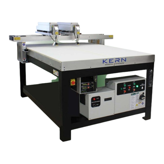
The recommended setup and operational testing is as follows: Description The DHS machine consists of a rectangular frame that is constructed from heavy angle section steel. The frame has four uprights on each corner, which act as legs. These support a worktop tray that is made of steel plate. -
Page 17: Intended Purpose
A second blower is connected at the nozzle assembly. Intended Purpose The DHS machine is capable of operating at speeds of up to 25 inches per second using a laser beam that operates at a consistent power level to provide high quality laser cutting or engraving over the entire area of the laser worktop. -
Page 18: Lighting
This Kern DHS model is designed for use indoors in a normal working environment. The intended operating temperature range is 16 - 32 degrees Celsius and a relative humidity range from 50 - 75%. -
Page 19: Computer
Place the KLMC on top of the DSP unit and set them on the shelf on the front of the system. All wiring harness connectors for the DSP and KLMC are labeled for ease of installation. The Kern KLMC and DSP boxes may be installed according to the directions below. - Page 20 KLMC & DSP Controllers Kern Laser Monitor Controller (KLMC) KLMC Back 1. Connect the HD15 male to the KLCM box. 2. Connect the DB15 male to the KLMC box. 3. Connect the green interlock plug to the KLMC box. 4. Connect the DB15 female to the KLMC box.
-
Page 21: Mounting Laser On Gantry
Universal Laser Mount Kern 100/150/200 Lasers Remove laser from the box. Set the laser on the two metal mounting blocks installed on the gantry plate. Snug the laser forward so that the beam output of the laser is pushed up against the silver metal tube of the shutter block. -
Page 22: Chilling Unit
A complete panel schematic is located inside of the electrical panel. This schematic is strictly to assist the electrician. If a schematic cannot be found, please contact Kern for a copy. Air/Assist Gas Connect 60-95 PSI of clean, dry air from an air compressor to the air quick connector located on the back of the laser system. -
Page 23: Mirrors And Lenses
Blower Hose Connections The hosing, metal clamps, extensions, and all other plastic fittings are included to hook up the blowers. The exhaust from the blowers must be run through a fume extractor or to the outside of the building. This may require the purchase of additional parts. Refer to the Blower Diagram in the Systems Diagrams chapter for proper installation of the blower hoses/tubes/adapters. -
Page 24: Daily Startup
Open KCAM. Draw a black hairline circle in CorelDRAW. File > Print Select the Kern EMF Printer Driver and click Print. The EMF file will automatically load into KCAM. Click on the Setup button to set your speeds and power in the Vector Colors tab. This screen will... -
Page 25: Cutting A .Plt File
The motion will pause at the start position of the deer on the table. Next the beam focus can be set to the material surface by placing the supplied Kern Laser Spacer. Place the spacer on the top of the material to be cut and slowly lower the focus optics down until it gently touches the spacer. -
Page 26: Engraving A .Tif File
The motion will pause at the start position of the deer on the table. Next the beam focus can be set to the material surface by placing the supplied Kern Laser Spacer. Place the spacer on the top of the material to be cut and slowly lower the focus optics down until it gently touches the spacer. - Page 27 Once the file is done the laser will return to its Home position. If laser system makes a grinding noise or acts out of the ordinary press the Emergency Stop switch and contact a Kern technical staff member.
-
Page 28: Mirror Alignment
New systems come fully tested and calibrated from the Kern factory. It is a good idea to check the alignment of your system after receiving your laser system. Please refer to the System Diagrams section of this manual for optics and mirror alignment diagrams. www.kernlasers... -
Page 29: Squaring The Table
9. Screw the top plastic screw back into the optics and gently snug to the lens. 10. Hook up the air hose and screw the laser nozzle back into the laser tube. 11. Cut the file again and verify that the narrowest cut on the paper is at a width of the Kern Laser Spacer. -
Page 30: Aligning The Engraving Pixels
Aligning the Engraving Pixels 1. In KCAM set your Lines Per Inch and Pixels Per Inch both to 60. 2. Open the Standard_DOT60.tif file in the Tests Folder. 3. Set a user offset in the Misc Settings tab so that the file is at the front and centered on the table. 4. -
Page 31: Installation
The KCAM software will be preinstalled on your laser system computer. All parameters for the KCAM software and servo motors are saved on a USB stick in your laser tool kit. Kern has also backed up these parameters at our facility. - Page 32 Edit Setting: Opens Setting menu. The speeds and power levels are set here. Edit System and Table Settings: Opens Table menu. Options in this menu are preset for your system. Please DO NOT edit these settings without consulting a Kern technical staff member. Lock Settings: Password protects various aspects of KCAM.
-
Page 33: Setup Icon
Table Map: Mapping program to increase table accuracy. These settings are preset and should not be adjusted without the help of a Kern support technician. Tcp Control: Used for Kern technician troubleshooting. Debug/Scope Windows: Used for Kern technician troubleshooting. - Page 34 Speed Vector cutting speeds for nine different colors can be set in the Speed column. The range of acceptable speeds is from .01 inches per second to 10 inches per second. Laser Power The laser power level for each color can be adjusted from 0 to 100%. Density The density is measured in Joules.
- Page 35 Setup, Vector Settings Laser Pierce Start Delay: Sets a delay which will give the laser a chance to penetrate the material to be cut. This setting should be left at 0 for normal operation. This setting is typically used when cutting thicker materials and metal cutting applications.
- Page 36 HPGL File Size and Placement Steps Per Inch: Match this setting to the output setting of your design software. Typically set to 1000. X left origin and Y bottom origin: Moves the placement of your file on the tabletop. Example: Set X left origin to 5 and Y bottom origin to 5 and all vector images move up and over 5 inches from its present location.
- Page 37 Slow speed: Each time the machine slows down for a change in angle, it will slow down to the speed entered here. This speed can range from .01 to 10 inches/sec. The intricacy of the cut will determine the speed entered. The more intricate, the slower the speed needs to be set. Stay Slow for: When the machine enters a corner or a radius, it will slow to the speed entered in the slow speed setting.
- Page 38 X-axis and lines per inch in the Y-axis. NOTE: The DPI is automatically set for you if you are using the Kern Printer Driver. Your image will be saved from your design software and opened in KCAM with the correct DPI. The DPI is set in the EMF Import tab.
- Page 39 EMF Import Tab This tab lets you choose the path in which your EMF files are saved to, and the DPI of your file. Setup Menu, EMF Import Win 2000/XP EMF Printer Driver Settings This menu will be displayed when you click the Edit button. Here you set your DPI, table size, and output location.
- Page 40 For best results use the same DPI for the X and Y. NOTE: It does not matter what Kern Printer Driver you select when this is checked, you will always print at the DPI entered here. When you uncheck this box the Kern Printer Driver from the Win 2000/XP EMF Printer Driver Settings section will take effect.
- Page 41 User Offset Enabled: Allows you to move your vector and images file in the X and Y direction. By typing a positive number, you can move artwork from the left side of the table to the right side of the table in the X direction. By typing a negative number, you can move artwork from the right side of the table to the left side of the table in the X direction.
- Page 42 Table Icon All table settings are calibrated at the factory. Contact Kern before making any changes to these parameters. Some adjustments may cause damage to the laser system. Please DO NOT exceed the maximum speeds listed below. The warranty of the system and laser will be voided if maximum speeds below are exceeded.
- Page 43 This section is for aligning your system when it is raster engraving. Please refer to the System Calibration section of this manual for complete instructions on how to perform the dot alignment test. NOTE: CONTACT KERN SUPPORT FOR CORRECT SETTINGS Table Settings, Tuning Feed Forward (For Mechanical Effects) Backlash Distance: Not currently used.
- Page 44 Time to Middle: The time to middle will either increase or decrease the effective area of the fine tuning numbers. The larger the number entered, the larger the effective area. This setting has a range of 0 to 30 milliseconds. Lasers Tab NOTE: CONTACT KERN SUPPORT FOR CORRECT SETTINGS...
- Page 45 Tickle Pulse: The tickle pulse is used to help keep the gas inside of the laser ionized. This setting is preset at Kern. The default value is 500. Table Tab NOTE: CONTACT KERN SUPPORT FOR CORRECT SETTINGS...
- Page 46 Motor Direction: The X and Y motors can move in two directions, forward and reverse. This setting allows the motors to reverse direction. The setting is preset at the factory. If a new motor or wiring harness is installed you may need to change this setting. Installed Options Second Air Valve: Call Factory Height Follower: Call Factory...
-
Page 47: Cut Icon
Tcp control interface For k-vision. Call Kern factory for correct settings. Controller Controller: Parallel or USB Controller Port: Set to 378 if using Parallel Port. Note command line Directory for note pad. TCP XPS Printer Server Call Kern factory for correct settings. - Page 48 Repeat Enable: When checked the laser will pause when finished with a file. By pressing the Enter key you can start the file over again. The pause can be removed under the Setup button, Misc settings tab, Automation section. Align each time: When checked, the system will go to the home position and align the table before repeating the file again.
-
Page 49: Test Icon (Test/Manual Mode)
Test Icon (Test/Manual Mode) The Test Mode allows users to manually test the motion, laser and other aspects of the laser system. This mode is also used when aligning the laser beam and setting the focal height of the nozzle. Manual Mode Current Position: Displays the current X and Y coordinates of the laser on the table top. -
Page 50: Metal Cutting
The metal cutting option is required to cut metal. This option, if ordered, is installed at the factory at the time of purchase. Oxygen assist through the high pressure optics is needed to initiate the cut and obtain a clean edge. This oxygen is controlled by the KCAM software and KLMC box. 150 and 200 watt lasers can be equipped with a metal cutting option. -
Page 51: Metal Cutting Optics Assembly
Kern Height Follower Controller. The gap from the metal being cut and the cutting tip can be adjusted until a desired gap is obtained. The Kern Height Follower will then maintain that gap over the metal even if the metal has any distortion in the metal and maintain the proper focusing point. -
Page 52: Overview
The k-vision package is a fully integrated hardware and software solution that allows for accurate registration and cutting of printed materials. This process starts with a nozzle mounted camera which automatically measures the dimensions between registration marks on a printed material. The system then uses these measurements and the registration marks of the original cutting file to compensate for shift, rotation and distortion. -
Page 53: Basic Settings Tab
BASIC SETTINGS TAB Contrast Multiplier: Sets the camera contrast setting. Brightness Adjust: Sets the camera brightness setting. Minimum Target Size: Sets the smallest target size the camera will accept. Set this slightly smaller than the actual printed target size. Maximum Target Size: Sets the largest target size the camera will accept. Set this slightly larger than the actual printed target size. -
Page 54: Advanced Settings Tab
ADVANCED SETTINGS TAB Camera to use: Target Detector Method: Matching algorithm used for calibration tests. Target Detector Shape: Preloaded image files for calibration tests. Default is BlackCircle. Target Detector Image: Custom .BMP file used for calibration tests. Mirror and average template image: Check 90 degree rotations: Manually accept all targets: When checked, must click accept for each target being found. -
Page 55: Calibration Settings Tab
CALIBRATION SETTINGS TAB Target Detector Method: Matching algorithm used for calibration tests. Target Detector Shape: Preloaded image files for calibration tests. Default is BlackCircle. Target Detector Image: Custom .BMP file used for calibration tests. Mirror and average template image: Check 90 degree rotations: Minimum Target Size: Sets the smallest target size the camera will accept. -
Page 56: Calibration Screen
CALIBRATION SCREEN Start Resolution: The Start Resolution feature compensates for fish eye and distortion. This procedure should be ran anytime the vertical distance from the camera to the nozzle tip has changed. To enter the calibration screen click Actions > Calibrate Vision Camera. 1.) Click Start Resolution. -
Page 57: Camera View Screen
Help: Close: Closes the Calibrate Vision Camera window. CAMERA VIEW SCREEN Target History: K-Vison keeps a history of the different targets that have been used. These targets can be accessed here. Arrow Keys: Clicking this allows the arrow pad to be accessed. This enables the user to manually move the camera/focusing head around. -
Page 58: Installing The Chuck Rotary Stage
A rotary attachment can be factory installed on Kern's laser systems for processing of pipes, rods and other cylindrical items. The rotary device is driven by a high resolution servo motor, resulting in smooth and accurate cutting performance. INSTALLING THE CHUCK ROTARY STAGE Turn ON the laser system and align the gantry. -
Page 59: Initial Setup
CorelDRAW is a graphics software that offers the ability to print over vector and raster files directly to KCAM through the Kern EMF Printer Driver. Files may also be saved as a .TIF or .PLT file and opened directly into the KCAM software. -
Page 60: Creating A .Plt Cutting File
C:\My Documents\KcamEMF > OK 12. Restart computer The Kern EMF printer driver allows for creation of an .EMF file that combines cutting and engraving into one common file. The file is created in a folder and then automatically opened into KCAM. To use the driver use the following steps: 1. -
Page 61: Setting The Cut Order
Setting the Cut Order 1. Once you have a file that you want to order go to the Tools tab and select Object Manager. 2. Your parts will show as a list at the right in the Object Manager box. 3. -
Page 62: Printing To Kcam
3. When done with AutoCAD drawing, go to File > Print. AutoCAD Print Screen 4. Use the following settings: Printer Name: Kern EMF Printer Driver (or similar name) Paper Size: Custom Plot Area: Extents Scale: 1:1, 1 inch = 1 unit Plot Style = acadlt.ctb... -
Page 63: Creating A Polyline
AutoCAD, Block Definition 3. Insert > Insert a. Name (choose block previously created) b. Insertion point (NOT selected) Scale (NOT selected) d. Rotation (NOT selected) e. Explode (selected) Click OK. AutoCAD, Block Insert Creating a Polyline If your file is sent over to KCAM as multiple line segments and not one continuous cut you can use the polyline function to combine it into one continuous line segment. -
Page 64: Installing Photograv
1. State PhotoGrav and go to File > System Defaults > Select Machine. 2. Choose the KERN HSE machine with appropriate laser size. 3. Under the Machine Properties select your laser wattage, max speed and a turn time of .142 seconds. -
Page 65: Daily
Maintenance and service procedures of the laser beam optics assembly (cleaning and maintenance of the lens and mirror) are to be conducted only by personnel who are familiar with laser safety and with the potential laser hazards from the product. Turn off the laser and close the shutter during lens and mirror cleaning, as operation of the laser without the lens or mirror installed can result in a potential laser hazard from the invisible output beam, even at distances of hundreds of feet away from the system. -
Page 66: Mirror
A dust/particle filter at the front panel of the chiller can be removed and cleaned with a compressed air gun. If the filter is clogged to the point where it cannot be cleaned out please contact Kern for a replacement filter. -
Page 67: Lens
of the mirror, check it for any physical damage. The mirrors have a shiny gold surface. It is very important to clean the optics if you think they are dirty or they will become permanently damaged. If the mirrors are chipped or cracked, cleaning of the optics will not repair the damage. -
Page 68: Lead Screw Nut Adjustment
4. Use the lens removal tool to unscrew the top lock ring. 5. The lens is now exposed and can be carefully removed by holding it by the sides only. Set the o-ring to the side. Use a clean rag or rubber gloves to carefully remove the lens. Avoid touching the front and back surface of the lens. - Page 69 Insert Mounting Body into the Inner Body Spline. With the Spring engaged in the Spring Adjustment Collar turn the Spacer Nut counterclockwise until the nut reaches its limit. NOTE: The Spring Adjustment Collar must be prevented from engaging with the Mounting Body while turning the Spacer Nut.
-
Page 70: Klmc Box
KLMC Box The Kern Laser Monitor Controller has multiple lights that will help indicate if there is a problem with the laser system. Make sure that all connections on the back of this box are secure before troubleshooting any further. - Page 71 This light indicates the RF power supply circuit has encountered a mismatched RF signal. The KLMC will shut off power to the laser to protect the laser and power supply. If this fault occurs, contact Kern for further assistance. Interlock This light indicates that the interlock circuit is opened.
-
Page 72: Dsp Box
Key Switch This light indicates if the key switch for the KLMC is cycled from ON to OFF. When the machine is turned ON for use you must cycle the key switch to clear the red light. There is a five second delay for the light to turn to green. -
Page 73: Computer
If the problem still exists have a certified electrician call a Kern technician to troubleshoot the electrical problem. Kern can provide wiring diagrams and pin outs to assist. -
Page 74: Laser
Failure of any of these will affect the performance of the laser and cause it to not fire. Laser Power Testing Procedure A laser power meter is required for this procedure. Please call a Kern sales associate for information on purchasing a laser power meter. These meters are great for troubleshooting and tracking the... -
Page 75: Mirror Alignment
Mirror Alignment... -
Page 76: Dhs Optics Assembly
DHS Optics Assembly... - Page 77 DHS Optics Parts List NUMBER QTY. DESCRIPTION PART NUMBER Lens Lock Ring HSE-1013 1.00" Diameter x 2.50" F.L. Lens 1585 1.00" Diameter x 5.00" F.L. Lens (not pictured) 1583 1.00" O.D. O-RING/Wave Washer 1898 Lens Saver 1485 2.50" Lens Holder N-HF-14 5.00"...
-
Page 78: Dhs Gantry
Gantry... - Page 79 Gantry Parts List NUM. QTY. DESCRIPTION PART NUMBER NUM. QTY. DESCRIPTION PART NUMBER STOP BLOCK 52-1067 52-1020 MOTOR FACE PLATE 1/4"-20 x 1.00 91255A542 (SERVO) 52-1100 TAIL NUT BLOCK 52-1042 X-MOTOR BELT 1066 BEARING 202 1065 5:1 GEAR REDUCER 1288 #10-32 x .750 SHCS 91251A345 #6-32 x .250 CPCS...
-
Page 80: Dhs Height Follower
Height Follower... - Page 81 DHS Height Follower Parts List NUM. QTY. DESCRIPTION PART NUMBER NUM. QTY. DESCRIPTION PART NUMBER #8-32 x .250 SET SCREW 91375A190 #8-32 x .500 SHCS 91251A194 10 TOOTH 1/4" BORE PULLEY 1095 HEIGHT FOLLOWER HOUSING HF-1000 FRAME 23 1/4" SHAFT...
-
Page 82: Blower Installation
Blower Installation Note: The HP of the blowers included with the system depends on your table size. - Page 83 Blower Installation Parts List NUMBER QTY. DESCRIPTION PART NUMBER 4” Clamps 2HP Blower 4” Plastic Elbow 4” Hosing 4” Plastic Splices 5” to 4” Rubber Connector...
-
Page 84: In Warranty Systems
The staff at Kern Electronics & Lasers, Inc. values our customers and takes great pride in the service we offer to our customers. The business relationships we have developed are very important to us. This page will clarify the service we offer to our customers after the purchase of a Kern Laser System. - Page 85 If you are out of warranty you will be billed for parts, labor, and shipping costs. This warranty does not cover shipment to customers outside of the USA. The shipping from Kern to the customer and vice versa will be covered by the customer for all shipping outside of the USA.
- Page 87 DHS GANTRY OPTICS BEAM SPOT ALIGNMENT SHEET...
- Page 90 1501 Industrial Drive Wadena, Minnesota 56482 • Phone 218-631-2755 • Fax 218-631-3476 • www.kernlasers.com...
Need help?
Do you have a question about the DHS and is the answer not in the manual?
Questions and answers